Table of Contents
Advertisement
Quick Links
General Specification
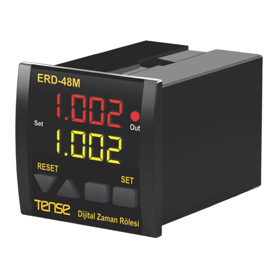
Digital Timer with START/RESET/GATE input and OUT1 & OUT2 outputs
2x4 7 Segment LED display
Selectable 13 different modes
Counts down hour/minute/second
Loads Timer value & OUT status at the latest power failure after the first power on
EEPROM memory to store settings
24VDC inputs (compatible with PNP proximity switch output)
48x48mm front panel
Warning:
!
Use twisted pair and shielded signal cables. Connect shield to ground from the device side. Keep all signal cables away
from circuit breakers, devices/cables emitting electrical noise and power cables.
Take precauitons against environmental conditions like humidity, vibration, pollution and high/low temperature during
installation.
Use a fuse (slow 250mA 250VAC) on supply input of the device. Use appropriate cables for supply connections. Apply safety
regulations during installation.
Technical Specification
:
Panel Hole Size
:
Display
:
Inputs
:
Gate Input
:
Output
:
Time base
: :
Modes
:
Sensor Supply Out
:
Supply Voltage
:
Pow. Consump.
:
Operating Temp.
:
Operating Altitude
44x44mm
2x4 Digit 7 Segment display
START / RESET / GATE
3x max. 32VDC (OFF:0....2VDC, ON:7....32VDC)
Inhibits count-down when GATE is ON.
Out Relay (NO-O-NC), 250VAC, 2A, Resistive load
Selectable; 99:59 hours / 99:59 minutes / 599.9 seconds
Selectable 13 different modes
12VDC, 50mA max.
100....240VAC, 50-60Hz
< 8VA
-20 C....55 C
o
o
< 2000m
1
ERD-48M
ENG
DIGITAL TIMER
MADE IN TURKEY
Advertisement
Table of Contents

Related Manuals for Tense ERD-48M


Summary of Contents for Tense ERD-48M
- Page 1 ERD-48M DIGITAL TIMER General Specification Digital Timer with START/RESET/GATE input and OUT1 & OUT2 outputs 2x4 7 Segment LED display Selectable 13 different modes Counts down hour/minute/second Loads Timer value & OUT status at the latest power failure after the first power on...
- Page 2 Connection Load ERD-72M 100 .. 240 VAC 50/60Hz 6VA +12V 30Vdc 50mA (Max) START RESET GATE SS Out Notes: “SS Out” return should directly connected to “GND pin”. Use free-wheeling diode to protect “SS Out” Dimensions: 15mm 48mm 75mm...
- Page 3 Programming Parameter: Front Panel RESET: Programming Timer SET Value: RESET Press for 3 sec. Press for 2 sec. Upper Display If Out is selected as; 0..7, 11, 12 Lower Second : 000.0..599.9 t.SEt Set Value Display Minute : 00.00..99.59 Hours : 00.00..99.59 Prog.
- Page 4 Modes of Operation: Mode: 0; ON Delay Mode: 7; One Shot after ON and OFF Out becomes ON when START Out becomes ON “t.SEt” after input is triggered (OFF > ON) START input is ON. Out is or (ON > OFF) and becomes Start Start OFF when START input is...
Need help?
Do you have a question about the ERD-48M and is the answer not in the manual?
Questions and answers