Table of Contents
Advertisement
Available languages
Available languages
Quick Links
9815 3rd Street Road,Louisville,
KY 40272,United States
Phone:833-290-1189
Email:info@acquaerpumps.com
Web:www.acquaerpumps.com
FOR ENGLISH
FOR SPANISH
WARNING: Read carefully and understand all ASSEMBLY AND OPERATION INSTRUCTIONS
before operating. Failure to follow the safety rules and other basic safety precautions may result
in serious personal injury
If you have any QUESTIONS, PROBLEMS, MISSING PARTS, please call our customer service
department at 833-290-1189 before returning to your retailer
Model:CJE050-1
.................................................................
.................................................................
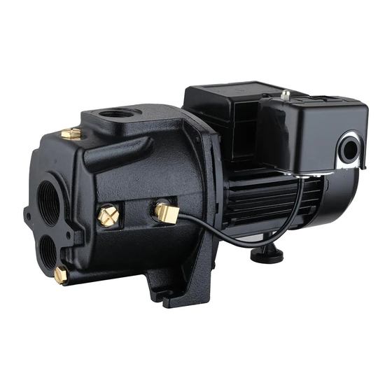
OWNER'S MANUAL
Convertible Jet Pump
Model:CJE050-1
El manual del propietario
Bomba de Chorro Convertible
Modelo:CJE050-1
Pages 02-13
Pages 15-26
Advertisement
Table of Contents

Related Manuals for Acquaer CJE050-1


Summary of Contents for Acquaer CJE050-1
- Page 1 9815 3rd Street Road,Louisville, OWNER’S MANUAL Convertible Jet Pump KY 40272,United States Model:CJE050-1 Phone:833-290-1189 El manual del propietario Email:info@acquaerpumps.com Bomba de Chorro Convertible Modelo:CJE050-1 Web:www.acquaerpumps.com Model:CJE050-1 ..............Pages 02-13 FOR ENGLISH ..............FOR SPANISH Pages 15-26 WARNING: Read carefully and understand all ASSEMBLY AND OPERATION INSTRUCTIONS before operating.
-
Page 2: Technical Specifications
TECHNICAL SPECIFICATIONS Model: CJE050-1 Specifications Property Voltage 115/230V~60Hz Horse Power 1/2HP Amps 7.2/3.6A Max. Head (ft.) 115 ft. Max. Flow (GPH) 310@5ft Discharge Size (in.) 1 in. Power cord length (ft.) PERFORMANCE GPH at 40psi discharge pressure Maximum Model pressure 5 ft. -
Page 3: Safety Information
SAFETY INFORMATION WARNING T his pump is meant to be used for shallow well or deep well applications. The pump can be equipped with the included ejector by attaching it to the front of the pump, and can operate at a 25 ft. vertical lift from the water level or less (shallow well pump). - Page 4 PREPARATION B efore beginning assembly of product, make sure all parts are present. Compare parts with package contents list and hardware contents above. If any part is missing or damaged, do not attempt to assemble the product. Contact customer service for replacement parts. ...
- Page 5 SHALLOW WELL INSTALLATION INSTRUCTIONS N OTE: Use a minimum of 1-1/4” diameter PVC piping for the suction pipe for best performance. A 1 in. MNPT x 1-1/4 in. SLIP adaptor will be needed to make the connection to the pump. WARNING ...
- Page 6 5 . U sing PVC purple primer and PVC cement, attach a 1-1/4 in. PVC elbow (not included) onto the rigid PVC pipe extending from the well seal. 6 . N OTE: This ejector must be attached to the front of the pump for shallow well application! Locate ejector (B) and place gasket (AA) over venturi tube (preassembled into the ejector (B)) so that openings in gasket (AA) match...
- Page 7 1 0. W rap thread tape (not included) around threads of a 1 in. discharge tee (not included). Using a pipe wrench, thread the 1 in. discharge tee into top of the pump. P roceed to the FINAL INSTALLATION INSTRUCTIONS on page 9. DEEP WELL INSTALLATION INSTRUCTIONS ...
- Page 8 4 . U sing PVC purple primer and PVC cement (not included), attach as many couplings and sections of rigid PVC pipe (not included) to the adaptor as it takes to equal the depth of the well minus 5 ft. ...
-
Page 9: Final Installation Instructions
9 . U sing PVC purple primer and PVC cement, attach as many sections of rigid 1 in. and 1-1/4 in. PVC pipe and couplings (not included) as needed to connect the 1-1/4 in. male PVC adaptor and the 1 in. - Page 10 3 . A ir pressure in the tank must be 2 PSI lower than the "cut-in" of the pressure switch. N OTE: The pump (A) has a 30/50 PSI pressure switch, which means the "cut-in" is 30 PSI; therefore, the tank needs to be set to 28 PSI.
- Page 11 PRESSURE SWITCH INSTALLATION INSTRUCTIONS WARNING! Before wiring the pressure switch, turn off the power source to which you are connecting to avoid potentially life threatening electrical shock. WARNING! It is recommended all electrical work be performed by a licensed electrician. WARNING! When wiring from the power source to the pressure switch, it is recommended that you use either a 14-gauge or 12-gauge cord.
- Page 12 Problem Possible Cause Corrective Action Power off Turn power on or call power company Blown fuse or tripped breaker Replace fuse or reset circuit breaker Pump does Faulty pressure switch Replace switch not start or Motor overload tripped Let cool. Overload will automatically reset Not enough water Stop motor;...
-
Page 13: Parts Diagram
PARTS DIAGRAM PARTS LIST Description Part No. ejector pump body drain cover impeller mechanical seal motor... - Page 14 9815 3rd Street Road,Louisville, OWNER’S MANUAL Convertible Jet Pump KY 40272,United States Model:CJE050-1 Phone:833-290-1189 El manual del propietario Email:info@acquaerpumps.com Bomba de Chorro Convertible Modelo:CJE050-1 Web:www.acquaerpumps.com Modelo:CJE050-1 ..............Pages 02-13 FOR ENGLISH ..............FOR SPANISH Pages 15-26 ADVERTENCIA: Lea cuidadosamente y comprenda todas las INSTRUCCIONES DE MONTAJE Y OPERACIÓN antes de operar.
-
Page 15: Especificaciones Técnicas
ESPECIFICACIONES TÉCNICAS Modelo: CJE050-1 Especificaciones Propiedad Voltaje 115/230V~60Hz Caballo de fuerza 1/2HP Amperios 7.2/3.6A Max. Cabeza(m) Max. Flujo(LPM) 19.5 tamaño de la descarga 1 in. Longitud del cable eléctrico RENDIMIENTO La presión LPM de agua a un total de metros de cabeza de 40 psi Modelo máxima de... -
Page 16: Información De Seguridad
INFORMACIÓN DE SEGURIDAD ADVERTENCIA E sta bomba está destinada a ser utilizada para pozos poco profundos o aplicaciones de pozos profundos. La bomba puede ser equipada con el eyector incluido por lo conecta a la parte delantera de la bomba, y puede operar a 25 pies. -
Page 17: Ubicación De La Bomba
PRECAUCIONES ADICIONALES DE SEGURIDAD U se gafas de seguridad en todo momento cuando se trabaja con bombas. S iga todos los códigos eléctricos y de seguridad, en particular el Código Eléctrico Nacional (NEC) y en el lugar de trabajo, la Ley de Seguridad y Salud Ocupacional (OSHA). ... - Page 18 TANQUES - ALMACENAMIENTO PRECARGADO P ara un mejor rendimiento de la bomba, se recomienda el uso de un tanque de presión de diafragma (no incluido). Lo mejor es tener esto en su lugar antes de instalar la bomba. Un tanque de almacenamiento de pre-cargada tiene una vejiga flexible o diafragma que actúa como una barrera entre el aire comprimido y agua.
- Page 19 3 . A ntes de deslizar el conjunto de la tubería en el pozo, sujete firmemente el montaje con una abrazadera de tubo (no incluido) para evitar que el conjunto se deslice hacia abajo en el pozo. ...
- Page 20 8 . E nvuelva la cinta alrededor de los hilos de rosca de un adaptador macho de PVC (no incluido). Enrosque el adaptador en la parte frontal del eyector (B). 9 . U sando cebador púrpura de PVC y cemento de PVC, adjuntar las secciones de rígido de 1 pulg.
- Page 21 E nvuelva cinta de hilo alrededor de ambos extremos de un 2 . 1 x 5 pulg. pezón (no incluido), y enrosque la boquilla en el agujero más pequeño del eyector (B). Apriete con la mano, luego apriete 1 vuelta con la llave de tubo.
- Page 22 7 . C orte el 1 pulg. tubo 2 pulg. más corto que el de 1-1 / 4 pulg. tubo. bordes ásperos suaves. Usando cebador púrpura de PVC y cemento de PVC (no incluido), adjunte un 1 pulg. codo de PVC y un 1-1 / 4 pulg.
- Page 23 INSTRUCCIONESDE LA INSTALACIÓN FINAL E stos pasos finales son los mismos para ambos pozos poco profundos y aplicación de pozo profundo. 1 . E nvuelva la cinta de hilo alrededor de los hilos de rosca de un 1 pulg.
- Page 24 P ara cebar, retire ambos: 5 . a. El enchufe de la parte superior del soporte de descarga (se llenará de agua aquí) , y; b. El enchufe en frente del soporte de descarga de la bomba (esto es para permitir que el aire de ventilación hacia fuera mientras el cebado).
- Page 25 Problema Causa posible Acción correctiva Sin batería Encender o llamar a la compañía Fusible fundido o se disparó el eléctrica La bomba disyuntor Cambiar el fusible o reiniciar el no arranca Interruptor de presión defectuoso disyuntor o funciona sobrecarga del motor actuada Reemplazar el interruptor Dejar enfriar.
-
Page 26: Diagrama De Piezas
DIAGRAMA DE PIEZAS LISTA DE PARTES Descripción Número de pieza eyector cuerpo de la bomba cubierta de drenaje impulsor sello mecánico motor...