Table of Contents
Advertisement
Quick Links
Contents
1 Preparing for installation ·········································································· 1-1
Safety recommendations ································································································································ 1-1
Examining the installation site ························································································································· 1-1
Temperature/humidity ····························································································································· 1-1
Cleanliness ·············································································································································· 1-2
Corrosive gas limit ··································································································································· 1-2
EMI ·························································································································································· 1-3
Laser safety ············································································································································· 1-3
Installation tools ·············································································································································· 1-4
Installation accessories ··································································································································· 1-4
2 Installing the switch ·················································································· 2-1
Installing the switch in a 19-inch rack·············································································································· 2-1
Installation methods ································································································································ 2-2
Rack mounting accessories ···················································································································· 2-2
Rack-mounting by using front and rear mounting brackets····································································· 2-4
Rack-mounting by using front mounting brackets and rack mounting rail kit ·········································· 2-6
Mounting the switch on a workbench ············································································································ 2-10
Grounding the switch ···································································································································· 2-10
Grounding the switch with a grounding strip ························································································· 2-10
Grounding the switch with a grounding conductor buried in the earth ground ······································ 2-11
Installing/removing a fan tray ························································································································ 2-12
Installing a fan tray ································································································································ 2-13
Removing a fan tray ······························································································································ 2-13
Installing/removing a power module ············································································································· 2-14
Installing a power module ····················································································································· 2-14
Removing a power module ··················································································································· 2-15
Connecting the power cord ··························································································································· 2-16
Connecting the power cord for a PSR150-A1 power module ······························································· 2-16
Connecting the power cord for a PSR150-D1 power module ······························································· 2-17
Verifying the installation ································································································································ 2-18
3 Accessing the switch for the first time ······················································ 3-1
Setting up the configuration environment ······································································································· 3-1
Connecting a console cable ···························································································································· 3-1
Connecting a DB9-to-RJ45 console cable ······························································································ 3-1
Connecting a USB-to-RJ45 console cable ······························································································ 3-2
Connecting a Mini USB console cable ············································································································ 3-4
Setting terminal parameters ···························································································································· 3-6
Powering on the switch ··································································································································· 3-6
4 Setting up an IRF fabric ··········································································· 4-1
IRF fabric setup flowchart ······························································································································· 4-1
Planning IRF fabric setup ································································································································ 4-2
Planning IRF fabric size and the installation site ····················································································· 4-2
Identifying the master switch and planning IRF member IDs ·································································· 4-2
Planning IRF topology and connections·································································································· 4-2
Identifying physical IRF ports on the member switches ·········································································· 4-3
Planning the cabling scheme ·················································································································· 4-4
Configuring basic IRF settings ························································································································ 4-5
Connecting the physical IRF ports ·················································································································· 4-5
Verifying the IRF fabric setup ·························································································································· 4-6
5 Maintenance and troubleshooting ···························································· 5-1
Power module failure ······································································································································ 5-1
Symptom ················································································································································· 5-1
Solution ··················································································································································· 5-1
i
Advertisement
Table of Contents

Related Manuals for H3C S5850 Series


Summary of Contents for H3C S5850 Series
-
Page 1: Table Of Contents
Contents 1 Preparing for installation ·········································································· 1-1 Safety recommendations ································································································································ 1-1 Examining the installation site ························································································································· 1-1 Temperature/humidity ····························································································································· 1-1 Cleanliness ·············································································································································· 1-2 Corrosive gas limit ··································································································································· 1-2 EMI ·························································································································································· 1-3 Laser safety ············································································································································· 1-3 Installation tools ·············································································································································· 1-4 Installation accessories ··································································································································· 1-4 2 Installing the switch ··················································································... - Page 2 Fan tray failure ················································································································································ 5-1 Symptom ················································································································································· 5-1 Solution ··················································································································································· 5-1 Configuration terminal display problems ········································································································· 5-2 No display ··············································································································································· 5-2 Garbled display ······································································································································· 5-2...
-
Page 3: Preparing For Installation
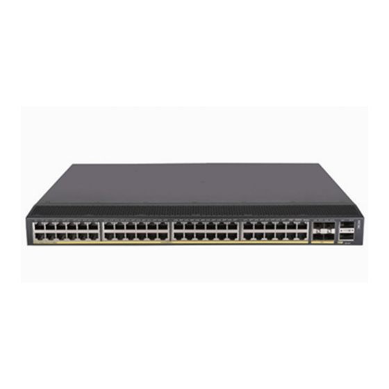
Preparing for installation H3C S5850 Switch Series includes only the S5850-54QS switch model. Safety recommendations To avoid any equipment damage or bodily injury caused by improper use, read the following safety recommendations before installation. Note that the recommendations do not cover every possible hazardous condition. -
Page 4: Cleanliness
• Lasting low relative humidity can cause washer contraction and ESD and cause issues including loose mounting screws and circuit failure. • High temperature can accelerate the aging of insulation materials and significantly lower the reliability and lifespan of the switch. For the temperature and humidity requirements of the switch, see technical specifications in Hardware Information and Specifications. -
Page 5: Emi
Average concentration (mg/m Maximum concentration (mg/m 0.05 CAUTION: As a best practice, control the corrosive gas concentrations in the equipment room at their average values. Make sure the corrosive gas concentrations do not exceed 30 minutes per day at their maximum values. -
Page 6: Installation Tools
The switch is a Class 1M laser device. Installation tools No installation tools are provided with the switch. Prepare the following tools yourself as required: • Flat-head screwdriver • Phillips screwdriver • Needle-nose pliers • Diagonal pliers • ESD wrist strap •... - Page 7 Item Product code Quantity Grounding cable 0404A06S Grounding screw 26010550 AC power cord 1, provided with the PSR150-A1 power 04041104 module NOTE: The AC power cord in this figure is for illustration only. The AC power cord for your country or region might differ from this one.
- Page 8 Item Product code Quantity...
-
Page 9: Installing The Switch
CAUTION: Keep the tamper-proof seal on a mounting screw on the chassis cover intact, and if you want to open the chassis, contact H3C for permission. Otherwise, H3C shall not be liable for any consequence. Figure2-1 Hardware installation flow Start... -
Page 10: Installation Methods
Installation methods Table2-2 Installation methods Installation Installation requirements Installation procedure methods • Install the front mounting brackets at the port side or power module side. • Install the rear mounting brackets according to the rack depth. If the rack depth is in the range of 329 ... - Page 11 Installation accessories S5850-54QS Rear mounting brackets and shoulder screws Provided (Figure2-5) Chassis rails and slide rails (Figure2-6) Optional Figure2-4 Front mounting bracket (1) Hole for attaching the bracket to a rack (2) Hole for attaching the bracket to the switch chassis (3) M4 screw Figure2-5 Rear mounting bracket and shoulder screw (1) Hole for attaching the bracket to a rack...
-
Page 12: Rack-Mounting By Using Front And Rear Mounting Brackets
Rack-mounting by using front and rear mounting brackets You can install the front mounting brackets at the port-side or power-side mounting position as needed. The following takes port-side mounting as an example. The power-side mounting is similar. This task requires two people. To install the switch in a 19-inch rack by using the front and rear mounting brackets: Wear an ESD wrist strap and make sure it makes good skin contact and is reliably grounded. - Page 13 Figure2-8 Attaching the rear mounting brackets to a rack with the wide flange inside the rack Figure2-9 Attaching the rear mounting brackets to a rack with the wide flange outside the rack Mount the switch chassis in the rack: a. One person supports the chassis bottom with one hand, holds the front part of the chassis with the other hand, and pushes the chassis into the rack gently.
-
Page 14: Rack-Mounting By Using Front Mounting Brackets And Rack Mounting Rail Kit
Make sure the front and rear mounting brackets have securely attached the switch to the rack. Figure2-10 Mounting the switch in the rack (with the wide flange of the mounting brackets inside the rack) Figure2-11 Mounting the switch in the rack (with the wide flange of the mounting brackets outside the rack) Rack-mounting by using front mounting brackets and rack mounting rail kit... - Page 15 To install the switch in a 19-inch rack by using the front mounting brackets and mounting rail assemblies: Wear an ESD wrist strap and make sure it makes good skin contact and is reliably grounded. Attach the front mounting brackets and the chassis rails to the chassis (see Figure2-12): a.
- Page 16 Figure2-13 Installing the slide rails Mount the switch in the rack: a. Verify that the front mounting brackets and chassis rails have been securely attached to the switch chassis. b. Verify that the slide rails have been correctly attached to the rear rack posts. c.
- Page 17 Figure2-14 Mounting the switch in the rack (1) Figure2-15 Mounting the switch in the rack (2)
-
Page 18: Mounting The Switch On A Workbench
Mounting the switch on a workbench IMPORTANT: • Ensure good ventilation and 10 cm (3.9 in) of clearance around the chassis for heat dissipation. • Avoid placing heavy objects on the switch. To mount the switch on a workbench: Verify that the workbench is sturdy and reliably grounded. Place the switch with bottom up, and clean the round holes in the chassis bottom with dry cloth. -
Page 19: Grounding The Switch With A Grounding Conductor Buried In The Earth Ground
Figure2-16 Connecting the grounding cable to the chassis (1) Grounding screw (2) Ring terminal (3) Grounding sign (4) Grounding hole (5) Grounding cable Verify that the grounding cable has been securely connected to the rear grounding point. Connecting the grounding cable to a grounding strip Use needle-nose pliers to bend the bare metal part to the shape as shown in Figure2-17. -
Page 20: Installing/Removing A Fan Tray
The dimensions of the angle iron must be a minimum of 50 × 50 × 5 mm (1.97 × 1.97 × 0.20 in). The steel tube must be zinc-coated and its wall thickness must be a minimum of 3.5 mm (0.14 in). Weld the yellow-green grounding cable to the angel iron or steel tube and treat the joint for corrosion protection. -
Page 21: Installing A Fan Tray
Installing a fan tray CAUTION: To prevent damage to the fan tray or the connectors on the backplane, insert the fan tray gently. If you encounter a hard resistance while inserting the fan tray, pull out the fan tray and insert it again. To install a fan tray: Wear an ESD wrist strap and make sure it makes good skin contact and is reliably grounded. -
Page 22: Installing/Removing A Power Module
Figure2-20 Removing a fan tray Installing/removing a power module WARNING! In power redundancy mode, you can replace a power module without powering off the switch but you must strictly follow the installation and removal procedures in Figure2-21 Figure2-22 avoid any bodily injury or damage to the switch. CAUTION: Provide a circuit breaker for each power module. -
Page 23: Removing A Power Module
a. Remove the screws on the filler panel. b. Use a flathead screwdriver to remove the filler panel. Figure2-23 Removing the filler panel Unpack the power module and verify that the power module model is correct. Correctly orient the power module with the power module slot (use the letters on the power module faceplate for orientation), grasp the handle of the power module with one hand and support its bottom with the other, and slide the power module slowly along the guide rails into the slot (see callout 1 in Figure2-24). -
Page 24: Connecting The Power Cord
Loosen the captive screws of the power module with a Phillips screwdriver until they are completely disengaged. Grasp the handle of the power module with one hand and pull it out a little, support the bottom with the other hand, and pull the power module slowly along the guide rails out of the slot. Put away the removed power module in an antistatic bag or the power module package bag for future use. -
Page 25: Connecting The Power Cord For A Psr150-D1 Power Module
Figure2-25 Connecting the PSR150-A1 (1) Figure2-26 Connecting the PSR150-A1 (2) Connecting the power cord for a PSR150-D1 power module WARNING! • To use a –48 VDC power source for power supply, use the power cord shipped with the power module. •... -
Page 26: Verifying The Installation
Figure2-27 Connecting the PSR150-D1 Verifying the installation After you complete the installation, verify the following information: • There is enough space for heat dissipation around the switch, and the rack or workbench is stable. • The grounding cable is securely connected. •... -
Page 27: Accessing The Switch For The First Time
Accessing the switch for the first time Setting up the configuration environment You can access the switch through the serial console port or the Mini USB console port. Only the Mini USB console port is available if you connect both the serial console port and Mini USB console port. Figure3-1 Connecting the console port to a PC You can use one of the console cables described in Table3-1... -
Page 28: Connecting A Usb-To-Rj45 Console Cable
Figure3-2 DB9-to-RJ45 console cable Table3-2 DB9-to-RJ45 console port signaling and pinout RJ-45 Signal DB-9 Signal CAUTION: • Identify the mark on the console port and make sure you are connecting to the correct port. • The serial ports on PCs do not support hot swapping. To connect a PC to an operating switch, first connect the PC end. - Page 29 Click the following link, or copy it to the address bar on your browser and download the USB-to-RJ45 console driver. http://www.h3c.com/en/home/USB_to_RJ45_Console/ View the TXT file Read me in the Windows folder to check whether the Windows system of the configuration terminal supports the driver.
-
Page 30: Connecting A Mini Usb Console Cable
Connect the Mini USB Type B connector to the Mini USB console port of the switch. Click the following link, or copy it to the address bar on the browser to download and install the driver on the configuration terminal. http://www.h3c.com.hk/Technical_Support___Documents/Software_Download/Other_Product /USB_Console/USB_Console/ Select a driver program according to the operating system you use: XR21V1410_XR21B1411_Windows_Ver1840_x86_Installer.EXE—32-bit operating... - Page 31 Figure3-5 Device Driver Installation Wizard Click Continue Anyway if the following dialog box appears. Figure3-6 Software Installation Click Finish.
-
Page 32: Setting Terminal Parameters
Figure3-7 Completing the device driver installation wizard Setting terminal parameters To configure and manage the switch through the console port, you must run a terminal emulator program, such as TeraTermPro, on your configuration terminal. You can use the emulator program to connect a network device, a Telnet site, or an SSH site. - Page 33 After the startup completes, you can access the CLI to configure the switch. For more information about the configuration commands and CLI, see H3C S5850 Switch Series Configuration Guides and H3C S5850 Switch Series Command References.
-
Page 34: Setting Up An Irf Fabric
Setting up an IRF fabric You can use H3C IRF technology to connect and virtualize S5850 switches into a large virtual switch called an "IRF fabric" for flattened network topology, and high availability, scalability, and manageability. IRF fabric setup flowchart... -
Page 35: Planning Irf Fabric Setup
You can affect the election result by assigning a high member priority to the intended master switch. For more information about master election, see H3C S5850 Switch Series IRF Configuration Guide. Prepare an IRF member ID assignment scheme. An IRF fabric uses member IDs to uniquely identify and manage its members, and you must assign each IRF member switch a unique member ID. -
Page 36: Identifying Physical Irf Ports On The Member Switches
As a best practice to avoid loop topology, first complete IRF configuration and then connect the IRF member switches. The S5850 switches can provide 10-GE/40-GE IRF connections through SFP+ ports/QSFP+ ports, and you can bind several SFP+ ports/QSFP+ ports to an IRF port for increased bandwidth and availability. -
Page 37: Planning The Cabling Scheme
If the IRF member switches are all in one equipment room, choose SFP+/QSFP+ cables. For more information about SFP+/QSFP+ cables and SFP+/QSFP+ transceiver modules, see ports in Hardware Information and Specifications. The following subsections describe several H3C recommended IRF connection schemes, and all these schemes use a ring topology. IMPORTANT: In these schemes, all physical IRF ports are located on the same side. -
Page 38: Configuring Basic Irf Settings
• To bind the ports on an interface card to an IRF port, you must install the interface card first. For how to install an interface card, see H3C S5850 Switch Series Interface Cards User Guide. • Execute the command to verify the basic IRF settings. -
Page 39: Verifying The Irf Fabric Setup
Wear an ESD wrist strap when you connect SFP+/QSFP+ cables or SFP+/QSFP+ transceiver modules and fibers. For how to connect them, see H3C Transceiver Modules and Network Cables Installation Guide. Verifying the IRF fabric setup To verify the basic functionality of the IRF fabric after you finish configuring basic IRF settings and connecting IRF ports: Log in to the IRF fabric through the console port of any member switch. -
Page 40: Maintenance And Troubleshooting
LED to identify fan tray failure. Symptom The status LED on an LSPM1FANSA-SN or LSPM1FANSB-SN fan tray is flashing yellow or off. Solution "Installing/removing a fan tray" to replace a failed fan tray. If the issue persists, contact H3C Support. - Page 41 Verify that the power module is supplying power to the switch. Verify that the console cable is correctly connected. Verify that the console cable does not have any problems and the PC settings are correct. If the issue persists, contact H3C Support. Garbled display Symptom The display on the PC is garbled.
Need help?
Do you have a question about the S5850 Series and is the answer not in the manual?
Questions and answers