Table of Contents
Advertisement
Quick Links
Advertisement
Table of Contents

Related Manuals for Haldex EB+ Gen 2


Summary of Contents for Haldex EB+ Gen 2
- Page 1 Operator’s Guide ELECTRONIC BRAKE SYSTEMS EB+ GEN 2 www.haldex.com...
-
Page 2: Table Of Contents
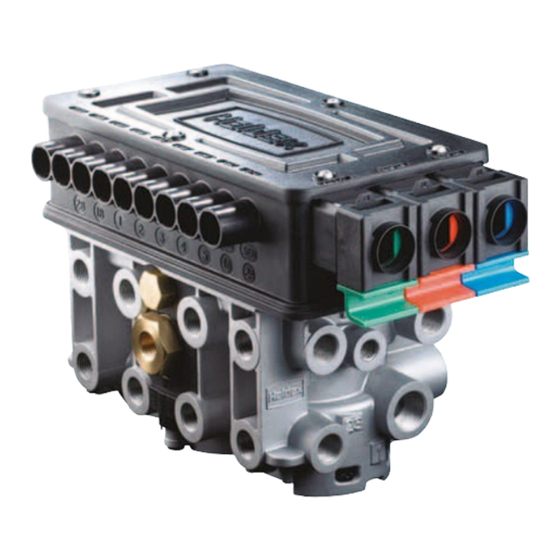
ECU Connector Identification Fig 1. The system is equally compatible with single and tandem axles. Wiring diagram The EB+ Gen 2 system is an integrated construction of an encapsulated Electronic Control Unit (ECU), Electro pneumatic relay Piping Diagrams valves (EPRV’s), over moulded connectors, integrated pressure transducers and a flash upgradable program memory. -
Page 3: General Components Guide
General Components Guide Haldex EB+ Gen 2 Assembly Sensor and Exciter ISO7638 - 7 Pin Socket assembly Driver’s EB+ Info Centre 2 information plate Park/Shunt and REV Options Option 1 Option 2 Option 3 Trailer Control Module (without check valve) -
Page 4: System Layout
• To indicate system integrity via the correct sequence (see Figs 10 ISO7638- 5 Pin - (No CAN data bus) ABS + ELS function only Fig 3. and 11 on page 10) every time the EB+ Gen 2 ECU is electrically powered up. -
Page 5: Chassis Components
Description Notes EB+ Gen 2 Label ISO7638 - 7 Pin Socket assembly Safety backup cable - ISO1185 (24N) EB+ Gen 2 Info Centre 1 & 2 (side of vehicle connection) EB+ Gen 2 ECU and EPRV’s assembly Sensor assembly Exciter COLAS®... -
Page 6: System Diagnostics
System Diagnostics An important feature of the EB+ Gen 2 system is that it provides an extensive on board diagnostic capability. The system displays a range of codes, which allow rapid diagnosis of the problem should one occur. Alternative positions... -
Page 7: Warning Device, System Check Procedure And Power-Up Modes
This information is described visually in Fig 14 on page 11. Power Up Modes The EB+ Gen 2 system has two power up modes. With switching the Ignition on (B+ applied) the following occurs: Fig 11 With no yellow line pneumatic pressure (i.e. -
Page 8: Test Procedure
SPIN EACH SENSED WHEEL IN TURN, Refer to diagnostic code listing. STEP 4 MULTIPLE LAMP SEQUENCE The Haldex EB+ incorporates a modified lamp flash of three flashes. Information Diagnostic The red lamp will flash when the system is powered up when at rest. -
Page 9: Diagnostic Trouble Codes (Dtc)
Diagnostic Trouble Codes (DTC) If a Diagnostic Trouble Code displayed is not listed here, check for intermittent sensor and wiring faults. DTC Displayed Possible Causes DTC Displayed Possible Causes ECU TIME OUT No supply on ignition switched line. EPRV 21 DUMP SC Modulator 21 dump solenoid short circuit DRIVE permanently energised... - Page 10 Diagnostic Trouble Codes (DTC) DTC Displayed Possible Causes DTC Displayed Possible Causes Reservoir Pressure Transducer Group Auxiliary Components Group RESR SC Reservoir pressure transducer short circuit AUX1 Auxiliary 1 system/wiring open or short circuit RESR OC Reservoir pressure transducer open circuit AUX2 Auxiliary 2 system/wiring open or short circuit...
-
Page 11: Ecu Connector Identification
ECU Connector Identification AUX 1 AUX 2, AUX 3 AUX 4 AUX 5 Colas, Reset-to-Ride Colas, Reset-to-Ride Lining Wear sensor Height Lateral Accelerometer Height General Prupose Input Retarder Control General Purpose Input Retarder Control Control Line Sensor 24 V Power Output Control Line sensor 24 V Power Output Soft Docking... -
Page 12: Wiring Diagram
Wiring Diagram Full System information (911-440-001) Fig 16 - Wiring Diagram (911-440-001) -
Page 13: Piping Diagrams
3 axle Semi-Trailer - 2 line air brake system Item Description Notes Emergency Coupling Service Coupling Pipe Filter Combined Park and Shunt Valve 352-044-... / 352-045-... Air Reservoir Drain Valve Test Point EB+ Gen 2 Assembly Spring Brake Chamber Single Diaphragm Brake Chamber Relay Emergency Valve Suspension Bellows... - Page 14 3 axle Semi-Trailer - 2 line air brake system with Trailer Control Module (without check valve) - Spring brake chambers Item Description Notes Emergency coupling Service coupling Pipe filter Trailer Control Module (without check valve) Air reservoir - service Drain valve Test point EB+ Gen 2 Assembly Spring Brake Chamber Single Diaphragm Brake Chamber Test Point Simulator Suspension Bellows...
- Page 15 3 axle Semi-Trailer - 2 line air brake system - Spring brake chambers Item Description Notes Emergency coupling Service coupling Pipe filter Combined Park and Shunt valve 352-046-001 Air reservoir Drain valve Test point EB+ Gen 2 Assembly Spring Brake Chamber Single Diapragm Brake Chamber Suspension Bellows...
- Page 16 Emergency coupling Service coupling Pipe filter Shunt Valve Air Reservoir Drain valve Test Point EB+ Gen 2 Assembly Spring Brake Chamber Single Diapragm Brake Chamber Suspension Bellows Relay Emergency Valve (REV) Park Valve Test Point Simulator Single Check Valve (optional)
-
Page 17: Multimeter Reading
Multimeter Reading Fig. 21 - Sensor connector Fig. 22 - Earth continuity Fig. 23 - COLAS connector Fig. 24 - ILAS -E connector ® ® B (+) B (+) Output Output A (-) A (-) Common Common Fig. 25 - COLAS DIN connector Fig. -
Page 18: Recommended Maintenance Schedule
Recommended Maintenance Schedule Time or Mileage Component Operation (whichever occurs first) When hubs are removed Exciter Check for damage Sensor Check for wear clean and readjust. Check output Every 3 months or Complete System Perform system check out and air leakage check. 25,000 miles (40,000 km) Annually or every or Complete System... -
Page 19: Part Reference
Part Reference Servicing Parts These available service parts can be obtained from Haldex service The different parts are shown in view form in order to allow easy centres or distributors. recognition. OE Part Description AM Part number View Number Electronic Control Unit (ECU) - Page 20 L = 2m AUX cable - Standard 815 015 001 Blanking Plug (Std Version) 027 5260 09 Sensor Extension Cable (5m) 814 007 111 EB+ Gen 2 Stability External Lateral Accelerometer 815 012 011 Info Point L = 7m Cable 815 021 001...
-
Page 21: General Information
EB+ Gen 2 Lining wear is a device that allows multiple lining wear indicators (LWI) to be connected to a single analogue input ‘AUX 4’ on the EB+ Gen 2 ECU. EB+ Gen 2 Lining wear device can be installed on all types of towed vehicles were provisions are made in the brake pads. - Page 22 Fax: +32 9 363 90 09 Fax: +52 81 8313 7090 E-Mail: info.BE@Haldex.com Brazil Poland Haldex do Brasil Ind. E Com. Ltda Haldex Sp. z.o.o. São Paulo Praszka Tel.: +55 11 213 55 000 Tel.: +48 34 350 11 00...
Need help?
Do you have a question about the EB+ Gen 2 and is the answer not in the manual?
Questions and answers