Table of Contents
Advertisement
Quick Links
Advertisement
Table of Contents

Related Manuals for Haldex EB+ CAN Hub


Summary of Contents for Haldex EB+ CAN Hub
- Page 1 INSTALLATION GUIDE INSTALLATION GUIDE CAN Hub Innovative Vehicle Solutions...
- Page 2 Notes on the use of this manual › This manual has been designed to assist personnel in Use appropriate spare-parts documentation when satisfactory installation of Haldex EB+ CAN Hub onto obtaining spare parts trailers. The intention has been to illustrate various ›...
-
Page 3: Table Of Contents
Installation EB+ CAN Hub Guide Contents Introduction ............... 4 EB+ CAN Hub versions ..........6 External pressure sensor ........... 10 Warning lamp ............13 Dimension and identification ........15 Chassis installation ........... 16 Excess cable ............. 22 Painting ..............23 Welding .............. -
Page 4: Introduction
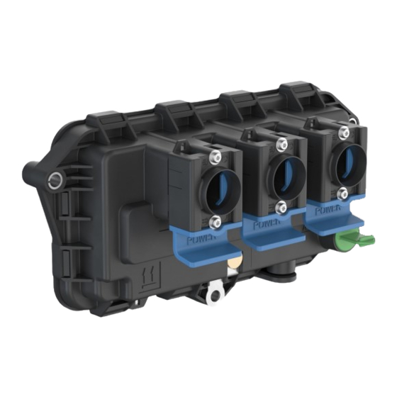
Introduction EB+ CAN HUB is an ISO 11992 router for 12 / 24 V EB+ EBS systems. It has three EB+ Power A (ISO 7638) connectors, sharing power and lamp connections but each having a separate ISO 11992 node and an input to connect an external pressure sensor for a commercial vehicle not equipped with ISO 11992 (i.e. - Page 5 Installation EB+ CAN Hub Guide The ISO 11992 CAN Bus is limited to 40 meters, where 22 meters is allocated for the truck (towing vehicle + Suzie connection) and a maximum of 18 meters for the trailer (towed vehicle). The maximum length to an ISO 7638 connector installed at the rear of the trailer is 15 m.
-
Page 6: Eb+ Can Hub Versions
A trailer with just one installed EBS ECU Connections to the EB+ CAN Hub and ECU (s) are made by EB+ Power A ISO 7638 cables connected to three 7–pin Haldex EB+ Power connectors located on the EB+ CAN Hub. - Page 7 Repeater EB+ CAN Hub is used as a repeater when the length of a cable allocated to the towed vehicle exceeds 18 meters. With EB+ CAN Hub connected there is down-stream support for up to 40 meters of ISO 11992 cable.
- Page 8 Reference the customer drawing 815 057 000 2 on page 45 for a wiring diagram example. Towed trailer with two local EBS units Both EBS units are connected to the same EB+ CAN Hub and both have the same trailer VIN number. This can be implemented only on the last trailer on the road train.
- Page 9 EBS fitted on a Dolly / Centre axle trailer CAN Hub CAN Hub fitted on a Dolly / Centre axle trailer EB+ CAN Hub as a router (with successor ECU i.e. another EB+ CAN Hub or EBS ECU on next trailer) Successor Local ECU...
-
Page 10: External Pressure Sensor
ABS only system) and towed vehicles equipped with EBS system. This is done through the connection of an external brake Pressure Sensor to the EB+ CAN Hub AUX port on the first trailer. The sensor provides information about the pneumatic brake demand requested by a driver and EB+ CAN Hub converts it into an electric brake demand signal and sends it to the trailers by generating the EBS11 (service brake demand) and EBS12 (pneumatic control line and 1 x electrical control line) messages. - Page 11 Installation EB+ CAN Hub Guide Removal of blanking plug The locking tab must be depressed before removing the green Pressure Sensor AUX blanking plug. Locking tab With a tool having a flat end of Ø 3-2 mm insert and press in locking While depressed pull out plug from housing.
- Page 12 Installation EB+ CAN Hub Guide Pressure Sensor cable insertion Ensure contact pins and seal are kept clean and free of any contamination prior to installation. Insert fully home in the ECU’s housing. Push connector into the ECU housing Ensure that the connector location tab clicks into place...
-
Page 13: Warning Lamp
The warning lamp is used to indicate when a fault has occurred. It can be triggered either by the EB+ CAN Hub ECU (working as a router or a repeater), or a local or a successor ECU (i.e. another EB+ CAN Hub in the road train, EBS ECU such as EB+ Gen3). - Page 14 System self-checked (not sensors) no further checks are required. 2 sec. 2 sec. @ 10 km/h If the results are not satisfactory, Haldex DIAG+ software or EB+ Info Centre should be used to establish the diagnosis. 2 sec. 2 sec.
-
Page 15: Dimension And Identification
Installation EB+ CAN Hub Guide Dimension and identification 107.5 mm 215 mm Ref no. Description Notes Connection for Power in or Power out Power A connection (any connection can be used for any function) Auxiliary connection Pressure Sensor connection ECU grounding strip... -
Page 16: Chassis Installation
Guide Chassis installation The EB+ CAN Hub ECU will be fitted directly to the trailer chassis using the three holes with compression limiters. The mounting fixing must provide an electrical connection between EB+ CAN Hub ECU and vehicle chassis. Deck of trailer... - Page 17 150 mm minimum 0.5 mm Additional bracket design to be as rigid as possible. The mounting fixing must provide an electrical connection between EB+ CAN Hub ECU and vehicle Mounting bracket chassis. The mounting bracket flatness is to be not more than 0.5 mm deviation from its true plane i.e.
- Page 18 Lock the ISO 7638 slide lock housing by pushing up the blue latch. Note: Blanking plug (027514709) and o-ring (024505009) must be fitted to the ISO 7638 connector if no cable is inserted (i.e. EB+ CAN Hub using only two ISO 7638 connectors). Innovative Vehicle Solutions 2020...
- Page 19 Installation EB+ CAN Hub Guide Trailer chassis Feed all connectors through the chassis with protective cap in place to avoid connector sockets being contaminated. ø 20.0 Remove protective cap from end of connector before connecting into the ECU. If required remove the blanking plug (027514709) from the ISO 7638 position.
- Page 20 Installation EB+ CAN Hub Guide Before inserting the ISO 7638 blue coloured 7-pin cable connector, ensure contact pins and seal are clean and free of any contamination prior to the installation. Position ISO 7638 cable on the slide lock housing, insert connector fully home.
- Page 21 Installation EB+ CAN Hub Guide All cables: the route of the cable from the connector should not start to bend so that the connectors are strained. Ensure stated minimum distance is not exceeded. 120 mm min ISO 7638 100 mm min...
-
Page 22: Excess Cable
Installation EB+ CAN Hub Guide Excess cable Excess cable must not be allowed to hang free, but must be attached to the chassis to prevent damage due to vibration and abrasion. Ø150 max 100 min Cable lengths less than 1 m to be coiled into loops of 100 mm minimum and 150 mm maximum diameter. -
Page 23: Painting
All electrical ports to have connectors or blanking plugs installed. Painting recommendations: water based, baking max. 1 hour @ 100 Electro static painting: Haldex recommends that the EB+ CAN Hub assembly is fitted to the trailer after electro static painting. 2020... -
Page 24: Welding
Installation EB+ CAN Hub Guide Welding The following precautions should be used during welding repairs or where heat is applied to the trailer for general repairs. Haldex welding recommendations: Disconnect any battery installed to the trailer and towing vehicle if connected. -
Page 25: Configuring Eb+ Can Hub
Configuring EB+ CAN Hub using DIAG+ The EB+ CAN Hub is configured using DIAG+ V6.20 onwards software. The DIAG+ software can be downloaded from the Trailer Application Guide section of the Haldex website. The DIAG+ Operators Guide can be downloaded from the Findex section of the Haldex website. - Page 26 Guide Connecting EB+ CAN Hub to DIAG+ Procedure Power down. Connect dongle (any ISO 7638 EB+ CAN Hub port can be used, but customers will likely use the towed connection). Power up. Dongle LED should be coloured red. Wait minimum 20 seconds (to allow EB+ CAN Hub to read any attached Gen3 VIN number / numbers).
- Page 27 Installation EB+ CAN Hub Guide Configure settings Click on the button to 'configure, read, setup and program the ECU'. Program ECU Menu Read ECU configuration from a previously saved file. Read configuration info from the ECU. Edit ECU parameters and configuration.
- Page 28 Installation EB+ CAN Hub Guide ECU parameters Click on the button to edit the ECU parameters and configuration. Edit ECU setup menu Walk through button. Setup the ECU configuration and layout. Setup load plate configuration. Display trailer information. Setup AUX configuration data.
- Page 29 20 seconds whilst the CAN Hub configures; then repeat again. This will allow CAN Hub to fully recognize the change. Before commencing ensure that only the local Gen3 (+ power) are connected into the EB+ CAN Hub. There may be a delay before DIAG+ and EB+ CAN Hub connect –...
- Page 30 Installation EB+ CAN Hub Guide To latch the VIN number click on Configure ECU icon Then click on Read Configuration Information from ECU icon: Click on Parameters and Configuration icon: Click on Display Trailer Information icon: Add VIN (Chassis number) if needed and then click “tick”...
- Page 31 “tick” icon (OK) to return to main DIAG+ dialog: Check displayed VIN is as expected: The local Gen3 VIN has now been latched into the EB+ CAN Hub. Now complete the CAN Hub configuration “double reset” – power down; power up then wait minimum 20 seconds whilst the CAN Hub configures;...
- Page 32 DIAG+ VIN configuration dialogs DIAG+ can display the assigned VIN (s) via the CAN Hub configuration dialog. Use DIAG+ to connect into the EB+ CAN Hub. Once a DIAGN connection is established the following should be done: 1. Click on Configure, Read, Setup and Program the ECU icon: 2.
- Page 33 Guide EB+ CAN Hub Connections Power: Predecessor connection to the EB+ CAN Hub (e.g. Truck, Trailer , another CAN Hub ..) Local: Connection to a Gen3 on the same trailer / dolly as that EB+CAN Hub is installed Towing: Successor connection to the EB+ CAN Hub (e.g. Trailer, Dolly, EB+ CAN Hub, Gen3 ...) Power: Predecessor connection to the EB+ CAN Hub (e.g.
- Page 34 Installation EB+ CAN Hub Guide Example 1: Normal towing - VIN not latched in CAN Hub Example 2: Normal towing - VIN latched in CAN Hub & 1x Gen3 (local) Example 3: Normal towing - VIN latched in CAN Hub & 1 x Gen3 (local). The successor trailer VIN can also be seen (towing).
- Page 35 Installation EB+ CAN Hub Guide Example 4: Normal towing - VIN latched in CAN Hub & 2 x Gen3 (i.e. 2 locals on the same trailer) Example 5: For “2 locals” configuration an extra icon will be shown on main DIAG+ dialog after CAN Hub configuration dialog has been run and the attached ECU VINs read.
- Page 36 EB+ CAN Hub Guide Enable / disable EB+ CAN Hub pressure sensor Use DIAG+ to connect into the EB+ CAN Hub. Once a DIAGN connection is established the following should be done: 1. Click on Configure, Read, Setup and Program the ECU icon: 2.
- Page 37 In EBS mode … then EBS11 messages stop - Pressure Sensor input then enabled And when Pressure Sensor input enabled … the lead EB+ CAN Hub is itself generating the EBS11 and EBS12 messages to the rest of the road train.
- Page 38 CAN Hub configures; then repeat again. This will allow CAN Hub to fully recognize the change. EB+ CAN Hub has now reconfigured successfully If the lamp is unexpectedly 'on' or a problem is suspected, use DIAG+ to connect into the EB+ CAN Hub to check the installed configuration.
- Page 39 EB+ CAN Hub will choose the designated local in a two locals configuration and that Gen3 is the ECU that will be read from / written to in the diagnostic session. If the user requires to read / write to the other local he must switch to that ECU using DIAG+.
- Page 40 Installation EB+ CAN Hub Guide Checking DTCs Procedure 1. From main dialog, click on the Service icon: 2. Then click on the relevant DTCs icon: For the local Gen3: Click on the first spanner Gen3 DTCs are displayed Innovative Vehicle Solutions...
- Page 41 Installation EB+ CAN Hub Guide For the EB+ CAN Hub: Click on the second spanner EB+ CAN Hub DTCs are displayed 2020 Innovative Vehicle Solutions...
-
Page 42: Software Update Limitations
EB+ CAN Hub Guide EB+ CAN Hub software limitations Flash update of local Gen3 via EB+ CAN Hub Towed port This is not supported. This can only be done via a direct connection to the Gen3. Fleet+ extraction of local Gen3 statistics via EB+ CAN Hub This is not supported. -
Page 43: Customer Drawing
Installation EB+ CAN Hub Guide Customer drawing 2020 Innovative Vehicle Solutions... - Page 44 Installation EB+ CAN Hub Guide Repeater version Innovative Vehicle Solutions 2020...
- Page 45 Installation EB+ CAN Hub Guide Router version 2020 Innovative Vehicle Solutions...
-
Page 46: Part Reference
Installation EB+ CAN Hub Guide Part reference These available service parts can be obtained from Haldex service centres or distributors. EB+ CAN Hub Part number EB+ CAN Hub 815 057 001 Pressure Sensor Part number M16 x 1.5 thread 815 022 001... - Page 47 Installation EB+ CAN Hub Guide ISO Cables ISO 7638 socket (unfused) Length 814 003 102 12 m 814 003 112 16 m 814 003 122 18 m 814 003 132 814 003 142 14 m 814 003 152 ISO 7638 plug (unfused)
- Page 48 Installation EB+ CAN Hub Guide Diagnostic cable ISO 7638 Diagnostic Length 815 018 001 0.5 m DIAG+ Part number EB+ Gen3 diagnostic cable kit 950 800 912 Kit contents: ECU / pc interface cable (6.5 m) 814 036 001 EB+ ISO diagnostic cable 815 018 001 EB+ SOV / pc interface cable (6.5 m)
- Page 49 Installation EB+ CAN Hub Guide Notes 2020 Innovative Vehicle Solutions...
- Page 50 Tel.: +1 816 891 2470 Fax: +1 816 891 9447 E-Mail: info.us@haldex.com ©2020, Haldex AB. This material may contain Haldex trademarks and third party trademarks, trade names, corporate logos, graphics and emblems which are the property of their respective companies. The...
Need help?
Do you have a question about the EB+ CAN Hub and is the answer not in the manual?
Questions and answers