Advertisement
ANNOVI
REVERBERI
The Power of Experience
INSTALLATION, OPERATION, AND PARTS MANUAL
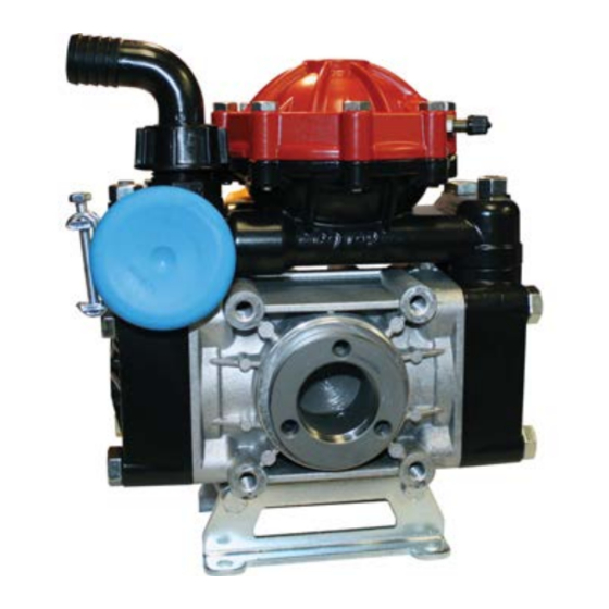
AR30-SP
AR40-SP
Pump with Base
AR30-GR3/4-GCI
AR40-GR3/4-GCI
Pump with Gearbox &
Control Unit
®
AR30 AR40
AR30-SP/A3/4
AR40-SP/A3/4
Pump with
3/4" Thru Shaft
AR30-CR3/4-GCI
AR40-CR3/4-GCI
Pump with Gearbox
& Control Unit
AR30
AR40
AR30-EM230-1
3 HP 230 Volt
Single Phase Motor
Advertisement
Table of Contents

Related Manuals for Annovi Reverberi AR30


Summary of Contents for Annovi Reverberi AR30
- Page 1 ANNOVI AR30 ® REVERBERI AR40 The Power of Experience AR30 AR40 INSTALLATION, OPERATION, AND PARTS MANUAL AR30-EM230-1 AR30-SP/A3/4 AR30-SP 3 HP 230 Volt AR40-SP/A3/4 AR40-SP Single Phase Motor Pump with Pump with Base 3/4" Thru Shaft AR30-GR3/4-GCI AR30-CR3/4-GCI AR40-GR3/4-GCI AR40-CR3/4-GCI Pump with Gearbox &...
-
Page 2: Drive Options
Pulley Kits Hydraulic Motor Flange Kit Pulley AR43396 has open sides AR43397 has closed sides For models AR30, AR50, AR303, AR403, AR503 (SP Models Only) 35 17 52 Fits SAE 2-bolt A Flange Motors with 1” Shaft AR1504 Kit Appl. P A 11"... -
Page 3: Electric Motor Drive
Electric Motor Drive AR30-EM230-1 3 HP 230 Volt Single Phase Motor 4 Pole 1700 RPM Operation IP54 Protection Against Rain and Splashing Water. L1 AND L2 ARE THE TERMINALS FOR THE CONNECTIONS OF THE WIRES FROM THE POWER CABLE AR30-EM230-1 550 ydRAulic iApHRAgm eigHT Amp Draw odel 36.2 AR30-EM230-1 69.5 33.7 32.5... -
Page 4: Control Unit Operation
Control Unit GI40 & GIC40 GI40 and GIC40 Control Units: Control units are available for easy flow and pressure control of your sprayer system. These units include a manual dump valve and adjustable pressure relief valve to control pressure, a liquid-filled pressure gauge to monitor pressure, and shut-off valves to control flow. - Page 5 Installation diagram (guideline) The following is a simplified illustration of the typical installation layout and is purely guideline. Control Unit by-pass Tank Agitation Control Unit Intake filter Pump Delivery line filter...
- Page 6 General guidelines on water supply connection General guidelines on water supply connection To operate correctly, the diaphragm pump must draw in liquids from containers at atmospheric pressure. Do not supply the pump with pressurized liquids. For continuous duty, the pump should not draw in water by gravity from containers with liquid level at heights above 9 feet.
- Page 7 Safety recommendations for handling and lifting Before starting the operations, organise the intended working area so that the materials can be lifted and handled in safety. Unloading, loading, handling and lifting operations must be carried out by skilled, authorised, specifi cally trained staff.
- Page 8 Installation • The crankshaft may turn in either direction. • The water connection with the pump must be made using hoses of suitable diameter, in all case no less than that of the pump fittings, securing them to the fittings using good quality clamps. The intake hose must be coil-reinforced to prevent restrictions.
- Page 9 Safety recommendations for use Before start-up, the operator must perform the necessary safety checks. In the event of leaks from the pressurized pipes, stop the pump at once and fix the leak. Do not operate the pump above the limits set by the manufacturer to increase its performance. Preliminary checks If the pump has a pressure accumulator, check its level of inflation, see "Checking the inflation pressure".
- Page 10 Safety recommendations for maintenance Before doing any maintenance work, depressurise the water system and isolate the pump from all en- ergy sources. When the jobs are done, before restarting the pump, check that no tools, rags or other materials have been left close to moving parts or in hazardous zones.
-
Page 11: Maintenance Instructions
MAINTENANCE INSTRUCTIONS Table of lubricants The pump is delivered complete with high-performance 30 weight, non-detergent oil suitable for the intended ambient conditions (see "Environmental operating limits"). Inspecting the pump mounting Check that the pump's fixing screws have not become loose. If necessary, tighten them with the driving torque stated in the installation design. - Page 12 MAINTENANCE INSTRUCTIONS Checking the inflation pressure If the pump has a pressure accumulator, check its level of inflation, with the pump shutoff using an air chuck fitted with a pressure gauge. The ac cumulator is inflated by the manufacturer for use of the pump at its maximum pressure.
- Page 13 Pump Storage It is important to comply with the recommendations for storage in the operator's manual of the machine into which the pump is incorporated. For the pump itself, at the end of pumping operations it is essential to flush out the internal circuit by pump ing clean water.
-
Page 14: Troubleshooting
TROUBLESHOOTING The information provided is intended to provide guidance how to deal with malfunctions which may occur during use. Some of these procedures may be carried out by skilled staff, while others have to be performed at specialised service centres since they require the use of specific equipment as well as detailed knowledge of repair opera tions. - Page 15 TROUBLESHOOTING Remedy Problem Cause Oil seal on pump Replace the worn oil seal. shaft worn. Oil on pump body or base. Oil pressure inside pump too high. Restore correct oil level in tank. Pump using too much oil (oil flowing from delivery port) or oil Stop the pump at once.
- Page 16 A.R. NORTH AMERICA A.R. NORTH AMERICA AR 30 SP & SP/A3/4 - AR 40 SP & SP/A3/4 50 49 New Inlet Pulsation Dampener April 2020 66 67 46 - 1 46 - 2 UP TO SERIAL NUMBER FROM SERIAL NUMBER 910400 910399 21 22 23...
- Page 17 Ø 29x3 620082 Diaphragm BlueFlex 620680 Key For 620172 620120 Piston Ø 56 620172 Shaft marked P ø 20 mm (P) AR30 620140 Connecting-rod 620174 Shaft marked R ø 3/4" (R) AR30 620110 Sleeve AR30 622210 Shaft ø 3/4" (R) AR40...
- Page 18 A.R. NORTH AMERICA A.R. NORTH AMERICA AR 30-GR3/4-GCI - AR 40-GR3/4-GCI 50 49 New Inlet Pulsation Dampener April 2020 66 67 48 - 1 48 - 2 UP TO SERIAL NUMBER FROM SERIAL NUMBER 910399 910400 21 22 23 68 69 70 20 48 - 3 48 - 4 50 49...
- Page 19 Ø 29x3 620082 Diaphragm BlueFlex 620680 Key For 620172 620120 Piston Ø 56 620172 Shaft marked P ø 20 mm (P) AR30 620140 Connecting-rod 620174 Shaft marked R ø 3/4" (R) AR30 620110 Sleeve AR30 622210 Shaft ø 3/4" (R) AR40...
- Page 20 A.R. NORTH AMERICA A.R. NORTH AMERICA A.R. NORTH AMERICA A.R. NORTH AMERICA A.R. NORTH AMERICA A.R. NORTH AMERICA A.R. NORTH AMERICA A.R. NORTH AMERICA A.R. NORTH AMERICA A.R. NORTH AMERICA A.R. NORTH AMERICA A.R. NORTH AMERICA A.R. NORTH AMERICA A.R. NORTH AMERICA A.R.
- Page 21 GI 40 / GIC 40 For GI 40 KIT 977 “I” KIT 982 “S” KIT 980“S” Build-in control unit and remote control AR 977 "I" AR 980 "S" AR 982 "S" Build in control Remote control Remote control Pos. Pos. Pos.
- Page 22 A.R. NORTH AMERICA A.R. NORTH AMERICA A.R. NORTH AMERICA A.R. NORTH AMERICA A.R. NORTH AMERICA A.R. NORTH AMERICA A.R. NORTH AMERICA A.R. NORTH AMERICA A.R. NORTH AMERICA A.R. NORTH AMERICA A.R. NORTH AMERICA A.R. NORTH AMERICA A.R. NORTH AMERICA A.R. NORTH AMERICA A.R.
- Page 23 A.R. NORTH AMERICA A.R. NORTH AMERICA AR 1666 : Gear Reduction Per - For: AR 30 - AR 303 - AR 403 Use of engine : B&S Vanguard 6.5 Kohler SH 265 Kohler SH 270 Honda GX 120 Honda GX 160 Honda GP 160 Honda GP 200 Axo AMG 120...
Need help?
Do you have a question about the AR30 and is the answer not in the manual?
Questions and answers