Table of Contents
Advertisement
Quick Links
______________________________________________________________________________________
Page 1/83
U
l
t
r
U
l
t
r
INSTALLATION
OPERATION
D
o
c
u
m
D
o
c
u
m
UltraGaugeBlue
a
G
a
u
a
G
a
u
&
e
n
t
V
e
r
s
i
o
n
e
n
t
V
e
r
s
i
o
n
™
User Manual
g
e
.
g
e
.
B
l
u
e
B
l
u
e
1
.
2
1
.
2
www.ultra-gauge.com
Advertisement
Table of Contents
Troubleshooting

Related Manuals for UltraGauge Blue


Summary of Contents for UltraGauge Blue
- Page 1 INSTALLATION & OPERATION ______________________________________________________________________________________ ™ UltraGaugeBlue Page 1/83 User Manual www.ultra-gauge.com...
-
Page 2: Warnings
Ultra-Gauge.com shall in no event be liable for any damages, whether direct or indirect, special or general, consequential or incidental, arising from any loss claimed as a result of the use of UltraGauge The UltraGauge... -
Page 3: Notices
Ultra-Gauge.com. UltraGauge is warranted to be free from defects in materials and workmanship for one year from the date of purchase. Within this period, Ultra-Gauge.com will, at its sole option, repair or replace any components that fail in normal use. Such repairs or replacement will be made at no charge to the customer for parts and labor, provided that the customer shall be responsible for transportation costs. -
Page 4: Table Of Contents
Install UltraGauge Blue Adapter ........................11 Connect via Bluetooth............................11 Optional: Mount Mobile Device in Vehicle ......................14 Starting the UltraGauge Blue Mobile Application ................... 14 Performing Basic Vehicle Setup ........................15 Setup Considerations ..............................17 English versus Metric Units ..........................17 Ignition on/off Detection............................ - Page 5 Email Log................................35 Set Log Level ..............................35 Tweak Gauges ............................... 36 Factory Default Gauges ............................37 Settings .................................. 38 UltraGauge Settings ............................38 Vehicle Settings ..............................41 Fuel Settings..............................49 Alarm Settings ..............................51 Custom Gauge List ............................... 54 Manufacturer Gauges ............................
- Page 6 Load absolute % ..............................68 Accelerator Pedal Position ..........................68 UltraGauge Battery Voltage ..........................68 Horsepower 1 ..............................68 Horsepower 2 ..............................69 % Engine Load ..............................69 Throttle Position Commanded .......................... 69 ECU Battery Voltage ............................69 Distance Since Trouble Codes Cleared......................69 EGR Error .................................
- Page 7 Using UltraGauge on more than one vehicle......................78 Troubleshooting ..............................78 Update Blue Adapter............................. 79 Air to Fuel Ratio (AFR) ............................80 Appendix C: Adapter Specifications ........................81 Appendix D: OBDII Compliancy decals ........................82 Appendix E: Document Revision History ........................ 83 ______________________________________________________________________________________ ™...
-
Page 8: Overview
Terms Alternate Terms Definition Purpose built computer(s) which control one or more of the Engine Control Unit vehicles systems. UltraGauge will access these via the Engine Control Module OBDII to access vehicle parameters. Title Bar Overall solution which includes: ... -
Page 9: Ultragauge Tm Features
Gauges o More than 78 selectable English Gauges* o More to than 46 selectable Metric Gauges* o UltraGauge OBDII Adapter Battery Voltage o Internal Temperature sensor that can be monitored and alarmed o Real time and long term mileage gauges o Distance-To-Empty &... -
Page 10: Ultragauge Overview
The key to the solution is the UltraGauge technology. It gathers, computes, and stores information about your vehicle any time the ignition is turned on. As a user, you can view and act on this data via the UltraGauge Mobile Application which automatically connects to the Adapter via Bluetooth when in range. -
Page 11: Installation
Application and connect to the UltraGauge Adapter and begin using UltraGauge Please see the install instructions found at http://ultra-gauge.com/blue/ Locate the vehicle’s OBDII connector. This connector is typically found above the foot controls and below the steering column. See the diagram below. In rare cases, the connector may be found in a similar location on the passenger side or even in the vehicle’s console. - Page 12 Press and Hold the BlueTooth Icon. This will bring up the Blue Tooth configuration screen. Switch on the BlueTooth if not already on. iii. The mobile device will scan and discover the UltraGauge Blue Adapter. The ignition must be in the START position iv.
- Page 13 The ignition must be in the START position. iv. The Apple device will then scan and find the UltraGauge Blue Adapter. Do not pair, proceed to the next step. The ignition must be in the START position and the mobile device must be within the vehicle.
-
Page 14: Optional: Mount Mobile Device In Vehicle
Adapter can be examined by selecting the Connection Status icon near the top left of the screen: The Connection status screen shows the status of the Bluetooth connection, and allows the selection of a given UltraGauge Adapter, if multiple Adapters are paired. -
Page 15: Performing Basic Vehicle Setup
Connection Information Performing Basic Vehicle Setup Now that your application is running, some initial vehicle parameters should be configured. This will allow UltraGauge to provide more accurate results. Select the “Vehicle Information” icon at the top of the Main Gauge Page: ______________________________________________________________________________________ ™... - Page 16 UltraGauge can attempt to retrieve this information automatically or it can be entered manually. To use automatic configuration, there must be a valid VIN displayed in the “VIN” field. If UltraGauge was able to retrieve this information from your vehicle, a valid VIN (similar to the one shown above) will be displayed in this field. If not, “Unknown” is displayed.
-
Page 17: Setup Considerations
Normally no intervention or configuration is necessary. However, in rare cases, some vehicles may mis-report the presence of a particular sensor which UltraGauge will then attempt to use to calculate the various mileage gauges, such as Instantaneous MPG, Average MPG, Gallons/Hour, etc. When this issue is present, many of the mileage gauges may display inaccurately or as “Err”. -
Page 18: Injector Cutoff Detection
UltraGauge Adapter. UltraGauge can be reset and returned to the factory default settings. Should configuration changes result in an undesirable setup, or UltraGauge becomes impaired, please see section regarding updating both the Mobile Application and the UltraGauge Adapter. -
Page 19: Operation
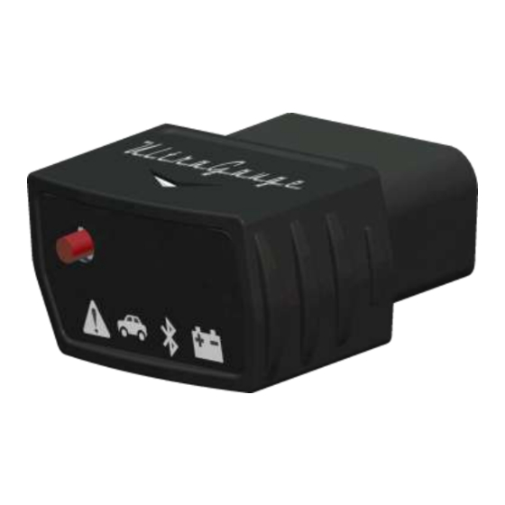
Random blink: OBDII traffic to/from vehicle Attention General purpose context dependent On: Indicates Blue is in a mode ready to download an update OR Blue is in Low Power mode (ignition off) Fast blink: Bluetooth Pair mode Off: none of the above ... -
Page 20: Button Operation
UltraGauge ScreensButton Operation UltraGauge Screens Below is an overview of the hierarchy of the UltraGauge screens. In the sections which follow, the functionality of each of these screens will be described. Note: In the following sections, you will see a “Navigate” tab (in the upper right hand corner) which describes how to navigate to the given screen on the UltraGauge Mobile Application. -
Page 21: Gauge Screen
Note: On Apple devices, tap anywhere on the screen to bring up the Gauge screen title bar. Navigate Direct Access The UltraGauge Application can display seven separate pages of gauges. Each page can independently be configured to display from 0 to 10 gauges. ______________________________________________________________________________________ ™... - Page 22 The expandable list will display gauges under group type titles. This allows UltraGauge to group gauges by “type”. For example, all the temperature gauges are under the “Temperature Gauges” list title, gauges like RPM/KPH/MPH are under the “Speed/RPM Gauges” title. This makes it quick to locate a given gauge without having to scan through all the gauges in one long list.
- Page 23 UltraGauge ScreensGauge Screen Navigate Modify a Gauge Gauges can be customized in a couple of different ways from the Gauge screen: Via Gestures Re-size: By using a pinching or stretching motion while on top of a specific gauge. ...
-
Page 24: One Click Away Access
One Click Away Access The following actions can be performed directly by pressing on one of the icons in the title bar of the Gauge screen. These actions include: View/change Bluetooth Connection Information to the UltraGauge Adapter View list of all active Alarms Rest Trip information (including Fuel tank fill-up) View/change Vehicle Information (Vehicle Name, Engine size, VIN, …) - Page 25 UltraGauge ScreensGauge Screen Navigate Connection Information This section describes the details of the state of the current Bluetooth connection between the UltraGauge Application and UltraGauge Adapter. The following sub-sections will describe each of the individual fields shown below: UltraGauge...
- Page 26 Note: When first discovered, the Adapter will attempt to retrieve the VIN from the vehicle. From the VIN, UltraGauge can determine the model year of the vehicle. If retrieving the VIN is not supported by this vehicle, the year will be left blank.
- Page 27 If selected, informs UltraGauge that the tank has been completely filled. Once filled, UltraGauge assumes the amount of fuel in the tank is equal to the fuel tank size. Once initiated, UltraGauge will then adjust the Fuel Level, TTE and DTE gauges accordingly. This menu item is only necessary for vehicles not reporting a fuel tank sensor.
- Page 28 Name: Friendly vehicle name used when connected to this vehicle Year: Model year of the vehicle. This may or may not be the purchase year of the vehicle. Used by UltraGauge when determining custom Mgauges, which may be supported for this vehicle.
- Page 29 On the driver's side door post. Note: By clicking on any of the WWW icons, UltraGauge will attempt to access the internet which is subject to the data plan associated with your mobile device or an available WiFi connection You will see messages at the bottom of the screen indicating connection to WWW and success or failure in deleting/uploading/downloading the vehicle information.
-
Page 30: Reset/Refuel Actions
UltraGauge will only allow a maximum amount of fuel to be entered that corresponds to the amount of fuel missing from the tank. If you pump more fuel than UltraGauge will allow, this likely means that the Fuel Tank Size setting has been set too low. -
Page 31: Empty Fuel Tank (Manual Mode Only)
(Manual Mode only) Informs UltraGauge that the Fuel Tank is empty. This affects the Fuel Level, TTE and DTE gauges. Typically Empty Fuel Tank is used along with Partial Tank fill up to set the initial amount of fuel in the fuel tank. -
Page 32: Readiness
Once a test completes, and the test is marked “Ready”, the test may have passed or failed. If the test failed there will likely be trouble codes posted. Note that UltraGauge is simply the messenger, relaying information from the vehicle’s ECU, and has no influence or impact upon the tests. - Page 33 UltraGauge ScreensCheck Engine/Readiness continue to be displayed in the Left Column, the right column will not be To restart/clear monitor status, select: affected. Check Engine/Readiness to clear Trouble Codes. This will clear any posted trouble codes and reset the readiness status This status is not always available.
-
Page 34: Diesel Engine
UltraGauge ScreensCheck Engine/Readiness Diesel Engine The readiness tests performed for a Diesel vehicle are different than those for gasoline vehicles. The readiness status will continually be read and displayed. As a result, if the ECU is busy running the monitors the status may change in real time. -
Page 35: View Logs
UltraGauge ScreensView Logs Navigate View Logs UltraGauge keeps a few independent logs to provide a history of events which have occurred, as well as to aid in troubleshooting any problems which might occur. ugAlarm Tracks the history of any Alarms which have occurred on any of the vehicles which the UltraGauge Application is monitoring. -
Page 36: Tweak Gauges
UltraGauge ScreensView Logs Navigate Tweak Gauges (Android Only—for Apple, double click on the gauge to adjust) Fine-tune gauge sizing/placement and much more… Customization which can be performed: For all Gauges: Re-size Set the width (in pixels) of the current gauge (height is auto-calculated) ... -
Page 37: Factory Default Gauges
UltraGauge ScreensView Logs (Android Only---For Apple Long press on Gauge Page Tweak Gauges Background) Restores the factory default Gauge assignments. When shipped UltraGauge has the following default gauge assignments: Page Gauge Instantaneous MPG Average MPG – General Instantaneous Gallons/Hour Fuel Level... -
Page 38: Settings
Foreground There are a couple of cases where the UltraGauge App makes audible sounds. When the App connects to the Blue Adapter, and when a Gauge Alarm is fired. This setting controls whether those audible sounds occur only while running the UltraGauge Application in the foreground (i.e. - Page 39 Code search URL When a Check Engine condition occurs, the UltraGauge App will display the list of Trouble Code conditions on the Get Trouble Codes screen. If you click on the WWW icon for a given Trouble Code entry, the App will search the WWW looking for a more detailed description of the code.
- Page 40 1. Force the protocol: Settings UltraGauge Settings->Force OBDII Protocol. Make sure and exit the Force Protocol screen to save the settings. 2. Unplug the Adapter 3. Start the vehicle 4. Insure the issue is not present, if present turn off the vehicle and repeat step 3.
-
Page 41: Vehicle Settings
Normally Auto is the correct and desirable setting and changes to this setting are not recommended. Certain vehicles misreport the presence of a sensor. When this happens, UltraGauge is not able to calculate the fuel usage and various mileage gauges may display “Err” or nonsensical values. All other gauges will display correctly. This setting is used to override the reported sensor and forces UltraGauge to use the selected sensor. - Page 42 If after calibration, it is found that the MPG results are still not accurate enough, the VE RPM value can be further adjusted. If UltraGauge reports less fuel used than actual, reduce the VE RPM by 200 and repeat Calibration. Likewise, if UltraGauge reports more fuel used than actual, increase the VE RPM by 200.
- Page 43 While in gear during de-acceleration, many vehicle manufacturers will turn off the fuel injectors in order to save fuel. This is true for vehicles with either manual or automatic transmissions. The fuel savings is slight. UltraGauge can detect when the injectors are switched off and factor the fuel savings into the fuel usage and mileage calculations.
- Page 44 Navigate SettingsVehicle SettingsVehicle CalibrationCalibrate MPG/Fuel Calibrate MPG/Fuel This calibration is used to fine-tune UltraGauge to accurately measure fuel usage. This calibration is critical, especially for vehicles which use a MAP sensor, diesels and alternative fuels. For vehicles that use a MAP sensor*, see the section on Adaptive Volumetric Efficiency before proceeding.
- Page 45 NOTE: Unplugging the Adapter after calibration will not cause loss of calibration. NOTE: Using the vehicle’s odometer to perform this calibration is pointless since the odometer and UltraGauge receive distance information from the same source; the vehicle’s ECU. NOTE: For best accuracy travel between markers at a high rate of speed.(50+MPH) ______________________________________________________________________________________ ™...
- Page 46 ECU to determine if it is powered and active. If a response is received, UltraGauge assumes that the ignition is on. This mode can also be used when mode 2 fails to cause UltraGauge to wake. However, this mode can result in battery drain on 2000 and newer GM vehicles and vehicles which use the CAN protocol.
- Page 47 “Power on Detect” modes. By default the voltage threshold is set to 13.2 volts and for most vehicles, this is the best setting. However, if when the vehicle is started, UltraGauge does not wake; decrease the threshold in 0.1 volt steps until UltraGauge wakes consistently.
- Page 48 This setting allows the number of “Power off Detect” mode attempts to be set from 2-255. Normally a value of 5 is best and preferred. If UltraGauge at times enters low power mode and briefly turns off its LEDs while the engine is running, increase the number of retries until the behavior stops.
-
Page 49: Fuel Settings
When disabled, the fuel sensor, if present, is ignored and UltraGauge continually calculates the amount of fuel used. The result is used by the Fuel Level, TTE and DTE gauges. In this mode it is necessary to inform UltraGauge each ... - Page 50 UltraGauge ScreensSettings NOTE: Some vehicles incorrectly report the presence of a Level Sender Mode or it is improperly implemented or it is defective. In these rare cases the Fuel Level % gauge will appear frozen or show a value unrelated to the fuel level. Other gauges that use the Level Sender, including DTE, Fuel Level, and Fuel Level % will also be in error.
-
Page 51: Alarm Settings
TCs or Pend TCs Gauges). Each gauge can have a high and low alarm. Each Low and High Alarm can individually be enabled and the value of each high and low alarm threshold can be individually set. UltraGauge continually compares real-time gauge values to each of the alarm values. - Page 52 UltraGauge ScreensSettings Navigate Enable/Disable All Alarms SettingsAlarm Settings Globally enables or disables all Gauge Alarms both audible and visual. Navigate Factory Default Alarms SettingsAlarm Settings Restores all gauge alarm settings back to the factory defaults. Table 2 - Alarm Factory Defaults...
- Page 53 UltraGauge Internal Temperature (ºC) Note! The more alarms enabled, the longer it takes UltraGauge to detect if a particular alarm has been triggered. If it is critical that a particular alarm generate an alert quickly, then disable other unimportant alarms.
-
Page 54: Custom Gauge List
UltraGauge can be used to access all of the ~135 standardized OBDII parameters, if supported, even on vehicles with 9141 or KWP2000 protocols. It’s important to understand that while the OBDII defines ~135 parameters, manufacturers only support a fraction of this; the older the vehicle, typically the fewer parameters supported. -
Page 55: Manufacturer Gauges
To add a gauge, click on the green “+” sign at the top of the screen. At this point, you will be asked whether you want to enter the Custom Gauge using the native UltraGauge Blue format, or whether you want to enter the Gauge using ScanGauges X-Gauge Format. - Page 56 1 Gauge: For each gauge created, UltraGauge will allow you to apply math for the creation of up to 2 separate Gauges. For example, this would allow the creation of a Metric and an English version of your gauge.
-
Page 57: Ultragauge Settings
UltraGauge Application Specific Version Number Version number of last/current Adapter connected to this Application UltraGauge UltraGauge comes with free minor updates for one year. Update information, if any, will be posted on the support page of the Ultra-Gauge.com website. ______________________________________________________________________________________ ™... -
Page 58: Appendix A: Gauges
Appendix A: Gauges The total potential available gauges are summarized in Table 3 - Potential Available Gauges. The actual number of gauges available is always vehicle dependent. The gauges supported for a given vehicle can be determined by the expandable list which is shown when adding a new gauge on the Main Gauge Page. - Page 59 Throttle Position Timing Advance (B1-B2/S1-S4) Wide O2 (B1-B2/S1-S2) Wide O2. * (B1-B2/S1-S2) Barometric Pressure inHG Evap Vapor Fuel Pressure (gauge) Fuel Rail Diesel 10kpa Intake Manifold Abs Pressure Average Fuel Average Fuel/Hr Average L/100km L/100km Average Speed Distance Fuel Cost Fuel Used Run Time h:m:s...
-
Page 60: Air Flow Gauges
MAF sensor, whereas Mass Air Flow Sensor 2 is the calibrated version used by UltraGauge to calculate MPG. The Mass Air Flow is calculated for vehicles that do not have a MAF sensor but rather use a MAP (manifold absolute pressure) sensor. -
Page 61: Distance Gauges
See the Fuel Sender Section for more details. With Fuel Tank Sensor: When a sensor is present via OBDII, UltraGauge can determine when the tank is refilled and DTE will be updated automatically. The distance to empty is determined by the current general average miles per gallon gauge;... -
Page 62: Time Since Ignition Start
Gauge name Range Units Abbreviation Time Since Ignition Run time since ignition on 0-65,535 h:m:s Ign RTime Start For non-hybrid vehicles, time will increment while the engine is running. It will stop if the engine stalls. Once the maximum value is reached, the timer will stop. For hybrid vehicles or for vehicles that employ engine shutoff strategies (e.g. -
Page 63: Time To Empty (Tte)
Without Fuel Tank Sensor: When a fuel level sensor is not available, or the Fuel Sender Mode is set to Disabled, UltraGauge has no ability to sense the actual fuel level. It is necessary that UltraGauge be informed each time the tank is filled. To do this, select from the Gauge screen. -
Page 64: Efficiency Gauges
For example, a vehicle with a VE of 50% is able to fill its cylinder with 50% of it potential. UltraGauge uses several engine sensors to determine the VE dynamically. This Gauge is only shown if the MAP sensor is present. -
Page 65: Fuel Gauges
When the Fuel Sender Mode is set to Enabled, the fuel level is calculated directly from the fuel tank sensor. When the Fuel Sender Mode is set to Disabled, it is necessary to inform UltraGauge manually that the tank has been filled. This is done via the menu system by selecting from the Gauge screen. -
Page 66: Fuel Trim
Even though the engine may contain two physical banks, only a single bank may be reported by the ECU. UltraGauge displays Fuel Trim Banks One and Two if reported by the vehicle’s engine computer. For those vehicles with three or four banks, only banks one and two will be available for display on UltraGauge. -
Page 67: General Trip Gauges
0 to 999.59 h:m:s Run Time General data is saved each time the ignition is set from RUN to OFF. Never unplug UltraGauge while the engine is running or current trip data will be lost. Average Fuel Average fuel economy. Based upon General Fuel used and General Distance Average Fuel rate since last reset. -
Page 68: Miscellaneous Gauges
UltraGauge measures this voltage and displays it as UltraGauge Battery Voltage. For all intents and purposes UltraGauge Battery Voltage and the vehicle’s Battery voltage are equivalent. As the battery voltage decreases, a point is reached where UltraGauge and the vehicle’s computer will no longer function. -
Page 69: Horsepower 2
Gauge name Range Units Abbreviation Horsepower 2 Horsepower 2 0 to 9999.9 Horsepower 2 Horsepower 2 is derived based on the amount of energy being consumed by the engine and the engine’s efficiency. By default the efficiency is assumed to be 24%. This means that only 24% of the energy contained in the fuel actually produces power or torque output. -
Page 70: Egr Commanded
Gauge name Range Units Abbreviation EGR % Flow 0 to 100 EGR Flow EGR Commanded The percent of flow through the Exhaust Gas Recirculation (EGR) valve, where 0% is closed and 100% is wide open. This is the commanded value indicating that the Engine Control Unit (ECU) is requesting the EGR to have the desired flow. -
Page 71: Torque 1
Gauge name Range Units Abbreviation Torque 1 ft/lbs Torque 1 0 to 9999.9 Torque 1 Horsepower 1 and Kilowatts 1 are derived from the vehicle’s Engine Control Unit. This gauge must first be configured by setting the maximum torque for the target vehicle. The maximum torque is a common parameter that can be found by searching the internet for the engine specification for your vehicle. -
Page 72: Wide O2 Sensor Output Lambda & Afr
Gauge name Range Units Abbreviation Wide O2 Bank1 Sensor 1 Wide O2 Sensor wO2 B1S1 lambda Output lambda & Wide O2 Bank1 Sensor 2 wO2 B1S2 lambda Wide O2 Bank2 Sensor 1 wO2 B2S1 lambda Wide O2 Bank2 Sensor 2 wO2 B2S2 lambda 0 to 1.999... -
Page 73: Boost Pressure
@ 14.64 PSI or 101 kPa. Maximum Boost is limited by the OBDII standard and not by UltraGauge. The limit is 22.5 PSI or 155 kPa Gauge name... -
Page 74: Short Trip Gauges
Gauge name Range Units Abbreviation 0 to 235 Short Trip Gauges Short Trip Average Fuel sTrip Avg 0 to 100 Short Trip Average Fuel Rate per 0 to 105.67 sTrip Avg Hour 0 to 400 Short Trip Average L/100km 0 to 999.9 L/100K sTrip Avg 0 to 158... -
Page 75: Mph/Kph
0 to 111 Temperature Internal temperature of UltraGauge. By default the high alarm is enabled and set to 145 ºF. NOTE: When the vehicle is started, after being off for more than 15 minutes, The UltraGauge Temperature will approximately equal the cabin temperature. -
Page 76: Trip Gauges
All trip gauges are zeroed by directly selecting: from the Gauge screen. Trip data is saved each time the ignition is set from RUN to OFF. Never unplug UltraGauge while the engine is running or current trip data will be lost. -
Page 77: Troubleshooting Gauges
Internal UltraGauge counter used to tell how many writes are queued up on UltraGauge Queue Mobile waiting to be sent to UltraGauge Blue. As the number of Gauges to be viewed are increased, this number should climb. This is mainly used for internal troubleshooting. -
Page 78: Appendix B: Miscellaneous
Most of the gauges displayed by UltraGauge do not indicate the units of measure used. All units are those most commonly used in the United States. There is no means to change the units of measure used or displayed by UltraGauge, rather select a gauge with the desired units. -
Page 79: Update Blue Adapter
If the download failed, the adapter may be unable to operate normally. Please follow the Note below. Note: In some cases after updating the Blue Adapter it MAY be necessary to re-Pair the Blue Adapter with your Mobile Device. Note: If for some reason the UltraGauge Application cannot connect to the Blue Adapter, you will need to perform the following steps to perform the update A. -
Page 80: Air To Fuel Ratio (Afr)
Occasionally we are asked if UltraGauge supports real-time AFR. We have in the past not supported it. Note that it is supported by the UltraGauge MX and UltraGauge Blue as a user programmable parameter, but is not recommended. Please read on to understand why. -
Page 81: Appendix C: Adapter Specifications
Appendix C: Adapter Specifications Voltage Range 10 to 16 Volts DC Interface OBDII compliant Protocols supported CAN 11-bit, CAN 29-bit J1850-VPM (GM) J1850-PWM (Ford) ISO 9141 (Chrysler and foreign) MSCAN SWCAN Operating temperature Range 0 ºF to 160 ºF Storage temperature range -20 ºF to 160 ºF (Warranty is void beyond these limits) Power less than 1/4 watt... -
Page 82: Appendix D: Obdii Compliancy Decals
Appendix D: OBDII Compliancy decals Every passenger vehicle or light truck sold in the USA since 1996 has been federally required to be OBDII compliant. Compliance is indicated on the emission decal located under the hood or possible in the door jamb. The decal is a black and white adhesive label, and can be found on the sill just before the radiator, on the underside of the hood, on the firewall, on the fender skirt, or just about any area under the hood that is somewhat flat and easily viewed. -
Page 83: Appendix E: Document Revision History
Appendix E: Document Revision History Doc Revision Date Detail October 11, 2015 First document release ______________________________________________________________________________________ ™ UltraGaugeBlue Page 83/83 User Manual www.ultra-gauge.com...
Need help?
Do you have a question about the Blue and is the answer not in the manual?
Questions and answers