Table of Contents
Advertisement
Quick Links
EM Plus 1.4c
UltraGauge EM plus
INSTALLATION
&
OPERATION
Document Version 1.00
for
Hardware version EM1.4c
(or greater)
For UltraGauge with a date version of 3/1/2019 or later
MENU UltraGauge Setup .. Version
____________________________________________________________________________________________
Page 1/63
UltraGauge™ EM User Manual
www.ultra-gauge.com
Advertisement
Table of Contents

Subscribe to Our Youtube Channel
Related Manuals for UltraGauge EM plus


Summary of Contents for UltraGauge EM plus
- Page 1 EM Plus 1.4c UltraGauge EM plus INSTALLATION & OPERATION Document Version 1.00 Hardware version EM1.4c (or greater) For UltraGauge with a date version of 3/1/2019 or later MENU UltraGauge Setup .. Version ____________________________________________________________________________________________ Page 1/63 UltraGauge™ EM User Manual www.ultra-gauge.com...
-
Page 2: Warnings
Liability The use of UltraGauge is at your own risk. Ultra-Gauge.com shall in no event be liable for any damages, whether direct or indirect, special or general, consequential or incidental, arising from any loss claimed as a result of the use of UltraGauge. -
Page 3: Display Cleaning
The display has a polarizing film over the glass. This film is very easily scratched and damaged. UltraGauge is shipped with a protective plastic film over the display to keep it clean. Many opt to leave the protective plastic film in place to protect the display. -
Page 4: Windshield Mounting Legal Notice
Limited Warranty UltraGauge is warranted to be free from defects in materials and workmanship for one year and the mounts for 6 months from the date of purchase. Within this period, Ultra-Gauge.com will, at its sole option, repair or replace any components that fail in normal use. Such repairs or replacement will be made at no charge to the customer for parts and labor, provided that the customer shall be responsible for transportation costs. -
Page 5: Table Of Contents
UltraGauge EM Table of Contents WARNINGS ................................2 INSTALLATION WARNINGS ..........................2 OPERATION WARNINGS ........................... 2 Liability ................................... 2 Battery Warning ..............................2 Fuse Warning ................................2 Display Cleaning ..............................3 Windshield Mounting Legal Notice ........................ - Page 6 Time To Empty (TTE) ............................32 Volumetric Efficiency % (MAP vehicles only) ....................33 UltraGauge Temperature ..........................33 UltraGauge Battery Voltage ..........................33 ..............................34 Gauge/Page Menu .. Select Gauges ............................... 34 ...
- Page 7 Power off Detect mode ............................47 Bat Low Threshold ............................... 47 Power off retries ............................47 KWP/9141 Optimize ............................48 Force MPG Sensor Injector Cutoff ............................... 48 ____________________________________________________________________________________________ Page 7/63 UltraGauge™ EM User Manual www.ultra-gauge.com...
- Page 8 Performance ................................59 ....................................59 ................................60 Miscellaneous Units of Measure ..............................60 Using UltraGauge on more than one vehicle......................60 Troubleshooting ..............................60 Specifications ................................ 61 Document Revision History ..........................61 ...
-
Page 9: Box Contents
UltraGauge protective plastic sleeve Optional: Mount(s) Optional: Hook & Loop Mount Mounting bracket – already attached to UltraGauge Warning insert with link to Website. UltraGauge™ EM Plus Features Supports most 1996 and newer OBDII compliant vehicles*** ... -
Page 10: Installation
The hook and loop fastener, commonly known as Velcro™, is comprised of two halves, each is 1"x1.5". One half is attached to the back of UltraGauge, as shown above. The 2nd half is attached to a surface inside the vehicle, such as the dash. The fastener may be used as-is or trimmed in size or cut in to several pieces. -
Page 11: Windshield Mount
Impact damage is not covered by the warranty. It is also possible to place slugs or washer behind the UP, DOWN and MENU keys such that pressing the front of UltraGauge depresses the switches, thus effectively converting the switches to the front. Examples can be found on the UltraGauge forum. - Page 12 Once the OBD-II connector is located, route the OBD-II cable so that it does not block or interfere with foot controls. The UltraGauge connector is a right-angle connector. This design limits the connector from protruding into the foot controls ____________________________________________________________________________________________ Page 12/63 UltraGauge™...
-
Page 13: Vertical And Horizontal Mounts
After application, and for maximum adhesion, allow the adhesive to set for 1 hour before use. When attaching the UltraGauge mounting bracket to the mount head, it is not necessary to fully seat the bracket. Slide the bracket onto the "T" notch until the bracket will no longer slide easily. -
Page 14: Start-Up & Configuration
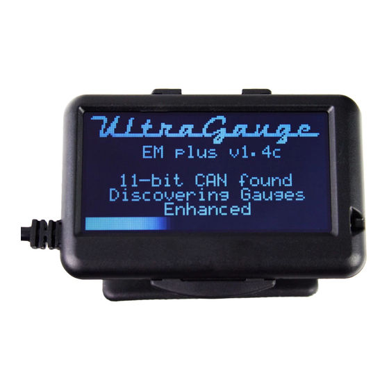
Start-up & Configuration When UltraGauge is first attached to the vehicle’s OBD-II connector it is immediately powered, as the vehicle’s OBD-II connector is always powered. Once connected UltraGauge will begin scanning the interface to determine the vehicle’s protocol. The vehicles ignition must be in the RUN position in order for UltraGauge to communicate with the vehicle’s Electronic Control Module (ECM). -
Page 15: Other Setup Considerations
There are three “ignition on” or Power On detection modes. When the ignition is switched to OFF, UltraGauge enters a low power mode where the display is powered off. When the ignition is switched from OFF to RUN, UltraGauge will detect this in 1-6 seconds and power back on. - Page 16 If you wish to move UltraGauge to another vehicle to use the trouble code functions, this can be done with no regard to configuration or calibration. The only exceptions are if force protocol has been set or 9141 optimization has been executed. These configuration items will need to be reset prior to moving to a different vehicle.
-
Page 17: Indicators
It is important that the light sensor window is not blocked as a result of installation. The Light Sensor Port is located on the front right side of UltraGauge, as shown above. - Page 18 During normal operation, to advance to the next page of gauges press and hold the DOWN arrow key for 1 second. UltraGauge will emit a tone when the page advance is recognized. Pressing DOWN on the last enabled page returns the display to page 1.
-
Page 19: Pages
º Once a gauge has been assigned to a zone, it is saved. The UltraGauge configuration is stored in non-volatile memory so that it is preserved through car start/stop cycles or when the unit is unplugged. The configuration remains until changed. -
Page 20: Gauges
Outside Ambient Air Temperature (ºC) UltraGauge Voltage Gauges in Blue are new for UltraGauge EM plus 1.4 *There are two possible sets of Lambda values returned by the ECM. One is current based and the other voltage based. While there is only one set of sensors and it would seem that a given vehicle would support either voltage or current, it is possible for the ECM to support both. -
Page 21: Engine Load
Fuel trim banks refer to the cylinder banks in a V style engine. Cylinder #1 is always in bank 1. Even though the engine may contain two physical banks, only a single bank may be reported by the ECM. UltraGauge displays Fuel Trim Banks One and Two if reported by the vehicle’s engine computer. -
Page 22: Fuel Pressure
99.2% rich fuel air mixture. Bank1 is the cylinder bank with spark plug #1. Typically only two O2 sensors are present, one on each bank. Some vehicles will support a wideband O2 sensor before the Catalytic converter and a narrow band after the Cat. ____________________________________________________________________________________________ Page 22/63 UltraGauge™ EM User Manual www.ultra-gauge.com... -
Page 23: Distance With Check Engine Light On
EGR Error = EGR (actual) – EGR (commanded) X 100 EGR (commanded) For example, if 20% EGR flow is commanded and 15% is actually delivered, then EGR Error is (15-20)/20 x 100 = -25% ____________________________________________________________________________________________ Page 23/63 UltraGauge™ EM User Manual www.ultra-gauge.com... -
Page 24: Evaporative Purge
0 to 400 Alternate to “% Engine Load” this gauge ranges from 0 to 95% for normally aspirated engines and 0 to 400% for boosted engines. This gauge is linearly correlated to Brake Torque ____________________________________________________________________________________________ Page 24/63 UltraGauge™ EM User Manual www.ultra-gauge.com... -
Page 25: Afr Commanded Ratio
Units Abbreviation Timing Fuel Injection Timing -210 to 302 FI º degrees Fuel Injection timing degrees relative to Top Dead Center (TDC). Positive degrees indicate before TDC, negative degrees indicate after TDC. ____________________________________________________________________________________________ Page 25/63 UltraGauge™ EM User Manual www.ultra-gauge.com... -
Page 26: Exhaust Pressure
PSI or 101 kPa. Maximum Boost is limited by the OBDII standard and not by UltraGauge. The limit for most vehicles is 22.5 PSI or 155 kPa. Boost Pressure is only supported if the vehicle has an Intake Manifold Absolute Pressure sensor also known as a MAP sensor, and the value of this sensor is made available via the OBDII.. -
Page 27: Instantaneous Mpg
General Distance by Gallons used, where Gallons is “Gallons – general”. General This gauge is reset by resetting the Average MPG: MENU Gauge/Page Menu .. Zero Ave MPG, G/H ____________________________________________________________________________________________ Page 27/63 UltraGauge™ EM User Manual www.ultra-gauge.com... -
Page 28: Trip Gauges
Gauge/Page Menu .. Zero All Trip Trip data is saved each time the ignition is set from RUN to OFF. Never unplug UltraGauge while the engine is running or current trip data will be lost. Distance traveled since trip was reset Distance Average Average fuel economy. -
Page 29: Short Trip Gauges
999 hours and 59 minutes is reached this timer stops. Run Time NOTE: The alarm for this gauge is set in hours and fractions of hours, not Hours and minutes. A setting of 0.5 is 30 minutes. ____________________________________________________________________________________________ Page 29/63 UltraGauge™ EM User Manual www.ultra-gauge.com... -
Page 30: Horsepower 1 Kilowatts 1
Note. Torque 1 & 2 are provided as competing methods of determining the power output of the engine. In general TRQ1 is likely to be more accurate. However, use which ever provides the most reasonable results for your vehicle. Torque 2 is typically better for modified engines. ____________________________________________________________________________________________ Page 30/63 UltraGauge™ EM User Manual www.ultra-gauge.com... -
Page 31: Fuel Level
When the Fuel Sender Mode is set to Enabled, the fuel level is calculated directly from the fuel tank sensor. When the Fuel Sender Mode is set to Disabled, it is necessary to inform UltraGauge manually that the tank has been filled. ... -
Page 32: Distance To Empty (Dte)
When a fuel level sensor is present, the DTE Gauge Range is 0 to 9999.9 miles Without Fuel Tank Sensor: When a fuel level sensor is not available, or the Fuel Sender Mode is set to Disabled, UltraGauge has no ability to sense the ... -
Page 33: Volumetric Efficiency % (Map Vehicles Only)
Volumetric efficiency is a measure of how fully your vehicle can fill its cylinders with the fuel/air mixture on the intake stroke. For example, a vehicle with a VE of 50% is able to fill its cylinder with 50% of it potential. UltraGauge uses several engine sensors to determine the VE dynamically. -
Page 34: Gauge/Page Menu
Un-assigns all gauges from all pages and zones. Not commonly used. Can be used when it is desired to reassign all gauges. Once unassigned the Main display will show no gauges. Load Default Gauges MENU Gauge/Page Menu .. Load Default Gauges Restores the factory default Gauge assignments. When shipped UltraGauge has the following default gauge assignments: Page Zone Gauge... -
Page 35: Page Settings
Select Gauge/Page .. Provides the ability to independently set the time that each of the 7 gauge pages are displayed before UltraGauge advances to the next page. The time may be set from 1 to 255 seconds. See Auto Page Advance above for more detail. -
Page 36: Partial Tank Fill Up
When disabled, the fuel sensor, if present, is ignored and UltraGauge continually calculates the amount of fuel used. The result is used by the Fuel Level, TTE and DTE gauges. In this mode it is necessary to inform UltraGauge each time the tank is filled. -
Page 37: Enabled
Low Threshold and Full Threshold. When the fuel level falls below the low threshold, the auto-fill function becomes armed. When the tank is filled and the fuel level exceeds the Full Threshold, UltraGauge triggers a Fill-up event automatically. -
Page 38: Smart Low Threshold
Normally Fuel Fill up or Partial Tank Fill up will be used to set the fuel in the tank. Note that once initiated, and after the menu is exited, the process starts and completes after several seconds. ____________________________________________________________________________________________ Page 38/63 UltraGauge™ EM User Manual www.ultra-gauge.com... -
Page 39: Vehicle Setup
Vehicle Setup .. Calibration.. Calibrate MPG/Fuel This calibration is used to fine-tune UltraGauge to accurately measure fuel usage. This calibration is critical, especially for vehicles which use a MAP sensor, diesels and alternative fuels. For vehicles that use a MAP sensor*, see the menu section on Adaptive Volumetric Efficiency before proceeding. -
Page 40: Reset Mpg/Fuel Cal
If you chose to travel several mile markers, then enter in the number of miles actually driven, for example, 3.000 miles. NOTE: Unplugging UltraGauge after calibration will not cause loss of calibration. NOTE: Using the vehicle’s odometer to perform this calibration is pointless since the odometer and UltraGauge receive distance information from the same source; the vehicle’s ECM. -
Page 41: Ve Enable (Map Only)
If after calibration, it is found that the MPG results are still not accurate enough, the VE RPM value can be further adjusted. If UltraGauge reports less fuel used than actual, reduce the VE RPM by 200 and repeat Calibration. Likewise, if UltraGauge reports more fuel used than actual, increase the VE RPM by 200. -
Page 42: Force Protocol
To avoid these issues, the Protocol & Interface can be fixed to that used by the vehicle. When the protocol is forced, UltraGauge will only try the set protocol. In the case of our 1999 Ford, UltraGauge will only drive pins 2 and 10, and will no longer attempt to drive pins 7 &... - Page 43 8. Once UtlraGauge has found the available gauges, start the vehicle and ensure the issue has been resolved Once forced, UltraGauge will likely not function if moved to a difference vehicle. This can be resolved one of three ways: 1. Prior to moving UltraGauge to a different vehicle select MENU Vehicle Setup ..
-
Page 44: Ultragauge Setup
Protocol found during the scanning process UltraGauge comes with free minor updates for one year. However, it is necessary to ship your unit in for the update, as it is not field updateable. Update information, if any, will be posted on the support page of the Ultra-Gauge.com website. All transportation costs are the responsibility of the user. -
Page 45: Compatibility
ECM to determine if it is powered and active. If a response is received, UltraGauge assumes that the ignition is on. This mode can also be used when mode 2 fails to cause UltraGauge to wake. However, mode 0 can result in battery drain on 2000 and newer GM vehicles and vehicles which use the CAN protocol. -
Page 46: Power Off Detect Mode
For most vehicles UltraGauge will correctly detect when the ignition has been switched to OFF with the default setting. Should UltraGauge remain on beyond 15 seconds after exiting the vehicle, use this setting to change the method UltraGauge uses to detect that the ignition is in the OFF position. -
Page 47: Bat Low Threshold
Alternatively consider Power off detect modes 3 or 5. A side effect of increasing the value is that UltraGauge will remain on for a longer period of time after the ignition is switched to Off. -
Page 48: Force Mpg Sensor
Normally Auto is the correct and desirable setting. Please do not change this setting unless you must. Certain vehicles misreport the presence of sensors. When this happens, UltraGauge is not able to calculate the fuel usage and various mileage gauges may display “Err” or nonsensical values. All other gauges will display correctly. This setting is used to override the reported sensor present and forces UltraGauge to use the selected sensor. -
Page 49: Display Settings
0% Brightness The sensitivity to the Ambient light can be adjusted via the Ambient Sensitivity menu setting. This setting allows UltraGauge to better adjust the Backlight brightness depending on the Vehicle’s ambient light. For example, vehicles with tinted windows or with smaller windows will have overall lower light levels and an increase in sensitivity would be recommended. -
Page 50: Backlite Max Brightness
Vehicles with tinted, smaller or fewer windows will have lesser ambient light levels. This setting allows UltraGauge to be tailored to your vehicle’s light levels. This setting has a range of from 0-100, with 100 being the most sensitive. -
Page 51: Alarms
Each gauge can have a high and low alarm. Each Low and High Alarm can individually be enabled and the value of each high and low alarm threshold can be individually set. UltraGauge continually compares real-time gauge values to each of the alarm values. If the real-time value is greater than the high alarm or less than the low alarm, an alarm is initiated. -
Page 52: Load Default Alarms
Outside Ambient Air Temperature (ºC) Throttle Position 2 % abs Accelerator Pedal Position 1 % Accelerator Pedal Position 2 % Throttle Position % Cmd Engine Oil Temperature F Engine Oil Temperature C ____________________________________________________________________________________________ Page 52/63 UltraGauge™ EM User Manual www.ultra-gauge.com... - Page 53 UltraGauge Internal Temperature (ºC) UG Voltage Note! The more alarms enabled, the longer it takes UltraGauge to detect if a particular alarm has been triggered. If it is critical that a particular alarm generate an alert quickly, then disable other unimportant alarms.
-
Page 54: Pending Tc Alarm
MENU Alarms .. Pending TC Alarm Enabling this alarm will cause UltraGauge to alarm if pending trouble codes are posted by the Vehicles ECM. The Vehicle will not light the Check Engine Light on the dash when pending codes are posted. -
Page 55: Trouble Codes
MENU Trouble Codes .. Pending Codes Displays any pending trouble codes as well as the number of pending trouble codes. UltraGauge can display up to 20 pending codes. Pending codes are potential issues discovered by the Vehicle’s ECM. These discovered issues are placed in the pending category and monitored by the ECM. -
Page 56: Emissions Readiness
This is a continuous real-time test. The OBDII standard requires that the ECM always report the status as ready. As such there is no point reporting the Fuel System monitor status, and it is not supported by UltraGauge Misfire Engine cylinder misfires test. - Page 57 However, it does not mean that the results of the test failed, only that the test completed or not. Once a test completes, and the test is marked “Ready”, the test may have passed or failed. If the test failed there will likely be trouble codes posted. Note that UltraGauge is simply the messenger, relaying information from the vehicle’s ECM, and has no influence or impact upon the tests.
-
Page 58: Gas Engine
As a result, if the ECM is busy running the monitors the status may change in real time. Pressing any key will halt the readiness status monitoring and exit to the Menu. The following potential readiness test status is presented by UltraGauge:... -
Page 59: Performance
Performance MENU More .. Performance UltraGauge can measure both acceleration and braking performance. Acceleration Performance Braking Performance 0-30 MPH 30-0 MPH 0-60 MPH 60-0 MPH 0-100 KPH (Km/H) 100-0 KPH 0-100 MPH 100-0 MPH 0-1/8 Mile 0-1/4 Mile Simply arm the gauge then go. -
Page 60: Miscellaneous
Units of Measure Most of the gauges displayed by UltraGauge do not indicate the units of measure used. All units are those most commonly used in the United States. There is no means to change the units of measure used or displayed by UltraGauge, rather select a gauge with the desired units. -
Page 61: Specifications
3.43” Wide x 2.14” Height x 0.50” Depth: Dimensions http://ultra-gauge.com/ultragauge/support/dimensions.jpg Power ~1W with display active, less than 1/4 watt with display off Document Revision History Doc Revision Date Detail 3/1/2019 First document release for EM Plus V1.4c ____________________________________________________________________________________________ Page 61/63 UltraGauge™ EM User Manual www.ultra-gauge.com... -
Page 62: Obdii Compliancy Decals
The following are just a few examples of emissions decals bearing the OBDII certification. Note that International vehicles may have very different appearing labels. ____________________________________________________________________________________________ Page 62/63 UltraGauge™ EM User Manual www.ultra-gauge.com... -
Page 63: Air To Fuel Ratio (Afr)
Air to Fuel Ratio (AFR) Occasionally we are asked if UltraGauge supports real-time AFR. We have in the past not supported it. Note that it is supported by the UltraGauge MX as a user programmable parameter, but not recommended. Please read on to understand why.
Need help?
Do you have a question about the EM plus and is the answer not in the manual?
Questions and answers