Table of Contents
Advertisement
Quick Links
Advertisement
Table of Contents

Summary of Contents for YAYKON PRIME-845A6
- Page 1 PRIME-845A6 Mainboard User’s Manual Rev:1.1 Date:2007.1...
-
Page 2: Table Of Contents
CONTENTS CHAPTER 1 PACKAGE CONTENTS ...... 3 CHAPTER 2 INTRODUCTION ......4 CHAPTER 3 MAINBOARD LOCATIONS ....7 CHAPTER 4 INSTALLATION ......8 ....... 8 UMPER ETTING AND CPU I ........9 NSTALLATION ......... 12 EMORY INSTALLATION IDE D ......13 EVICES NSTALLATION ...... - Page 3 ......32 OWER ANAGEMENT ETUP P/PCI C ......34 ONFIGURATIONS ......35 EFAULTS ......35 PTIMIZED EFAULTS 6.10 C ........36 HANGE ASSWORD 6.11 S & W ....37 ITHOUT ETUP...
-
Page 4: Chapter 1 Package Contents
Chapter 1 Package Contents Your mainboard package contains the following items: One mainboard One 80-Pin Ultra DMA 66/100 IDE drive ribbon cable One 34-Pin Floppy drive ribbon cable Software install CD One user’s manual One I/O Backboard... -
Page 5: Chapter 2 Introduction
Chapter 2 Introduction This mainboard has the Intel 845 chipset that contains Intel 82845GV Memory Controller Hub and Intel 82801DB I/O Controller Hub. This mainboard has a Socket-478 support for Intel Pentium4 processors with front-side bus(FSB)speeds up to 400/533,supports DDR200/DDR266 memory bus, supports AC97 audio codec ,integrated AC97 audio that supports full surround sound with up to Two channels, front panel audio output function, provides Ultra DMA66/100 function, the integrated display function technologies without... - Page 6 -Integrated display function technologies without extend VGA card Integrated 2D/3D Graphics Controller -USB Ports Six USB ports Supports compliant with Universal Serial Bus Specification Revision 2.0 -IDE Port Provides two channel connecting four IDE drives Supports Ultra ATA66/100 synchronous DMA modes -I/O Ports One floppy port support format 360K/720K/1.2M/1.44M/2.88M disk driver One serial ports...
- Page 7 -Dimension Micro ATX form factor...
-
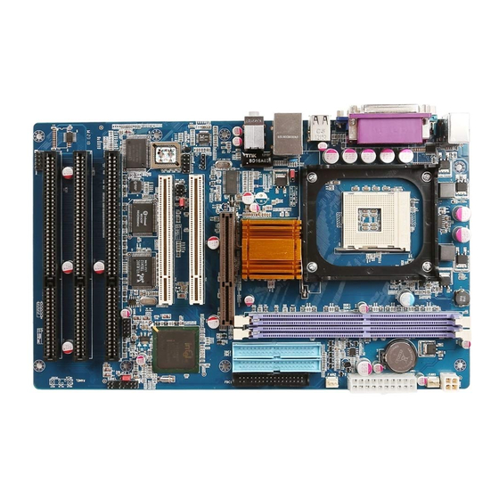
Page 8: Chapter 3 Mainboard Locations
Chapter 3 Mainboard Locations... -
Page 9: Chapter 4 Installation
Chapter 4 Installation 4.1 Jumper Setting and Slot FSB CPU Frequency Jumper Setting JUPER AUTO(Default) OPEN JP3:Clear CMOS Jumper Setting 1-2(Default) Normal Clear CMOS Audio:Front panel Jumper setting Function Function MIC+ Ground Vbias AuD_Vcc(AVCC) AuD_R_Out AuD_R_Out Back N.C. AuD_L_Out AuD_L_Out Back USB: Expansion Connector Function Function... -
Page 10: Cpu Installation
PS/2(Top) PS/2 Mouse Header(Up Green) USB1/2 USB1/2 Connector Port USB3 USB3 Connector Port Printer Connector Port VGA Display Connector Port COM1 Serial Ports COM1 Connector Port MIDI MIDI Port LINE OUT/LINE IN/MIC Audio Output/Audio Input/Microphone CD_IN CD-ROM Audio Input Port IDE1/IDE2 Primary IDE/Secondary IDE Port Floppy Disk Drive Connector Port... - Page 11 use the retention module clamps to snap the fan/heatsink into place. 6.Plug the CPU fan power cable into the CPU cooling fan power supply connector on the mainboard.
-
Page 13: Memory Installation
4.3 Memory installation This mainboard supports DDR200/DDR266 DDR memory , you may install 64/128/256/512MB 184 pin DDR memory。DDR SDRAM uses additional power and ground lines and requires 184-pin 2.5V unbuffered DIMM module rather than the 168-pin 3.3V unbuffered DIMM used by SDRAM. Follow these instructions to install the Memory: 1.Push the latches on each side of the DIMM slot down. -
Page 14: Ide Devices Installation
4.4 IDE Devices Installation IDE devices include hard disk drives, high-density diskette drives, and CD-ROM or DVD-ROM drives, among othes. The mainboard ships with and IDE cable that can support one or two IDE devices. If you connect two devices to a single cable, you must configure one of the drives as Master and one of the drives as Slave. - Page 15 can clear the CMOS memory of date, time, and system setup parameters by erasing the CMOS RTC RAM data. The RAM data in CMOS, that include system setup information such as system passwords, is powered by the onboard button cell battery. 1、...
- Page 16 minimum recommended wattage is 300W or above for a fully configured system. The system may become unstable and may experience difficulty powering up if the power supply is inadequate. Note2: Do not forget to connect the 20-pin ATXPWR1 and 4-pin ATX12V1 power plugs.
-
Page 17: Chapter 5 Driver Installation
Chapter 5 Driver Installation 5.1 Installation Directory The utility CD is supplied with that mainboard the connects contained in it are showed as below: Directory Driver Windows 9x INTEL\INF\XXX Intel chipset software Windows 2000/XP Windows NT4.0 Windows 9x Realtek AC’97 Audio SOUND\REALTEK\XXX Windows 2000/XP... - Page 18 Click“NEXT”to continue Select“YES” to continue...
- Page 19 Select“NEXT” to continue Select“FINISH” to complete the installation.
-
Page 21: Sound Driver Setup
Select“Finish”to complete the installation 5.3 Sound Driver Setup 5.3.1 Sound driver setup Insert the driver CD, running driver software CD, choose the directory:\CD-ROM:\SOUND\REALTEK\Setup.exe Select“Next”to continue Continue... - Page 22 Select“YES” to continue Select“Finish”to complete the installation 6-Channel Sound Output Support Please follow the steps below for operation(optional) : 1.After install sound driver,click “Sound effect”, “AC97 Audio configuration”options; 2.Click “Sound configuration”,select “6 Channel mode for 5.1 speakers output” options。 3.Click “Sound effect” menu “Environment”,you must choose one Sound...
-
Page 23: Usb 2.0 Driver Setup
effect realization 6-Channel sound output。 5.3.2 Uninstalltion Sound Driver (For Realtek of WIN98 operation system) Startup to WINDOWS desktop,select“Setup”/“Control Panel” ,select “Add/Delete” menu select“Avance AC’97 Audio Driver and Applications” , click “Add/Delete ” , select “language” , “confirm” “ GO ” ,select “Complete”... - Page 24 Select“NEXT”to continue Select“YES” to continue...
- Page 25 Select“Finish”to complete the installation...
-
Page 26: Chapter 6 Bios Setup
Chapter 6 BIOS Setup The BIOS Setup Utility record settings and information of your computer, such as date and time, the type of hardware installed, and various configuration settings. Your computer applies those information to initialize all the components when booting up and basic function of coordination between system components. - Page 27 press PgUp and PgDn keys to cycle through alternative values of that item. The other options on the main menu page lead to dialog boxes that require your answer Yes or No by hitting the Y or N keys. If you have already changed the setup utility, press F10 to save those changes and exit the utility.
-
Page 28: Standard Cmos Features
6.2 Standard CMOS Features Date(mm:dd:yyyy) These items set up system date Time(hh:mm:ss) These items set up system time Pri/Sec Master/Slave These items configure devices connected to the Primary and Secondary IDE channels. To configure an IDE hard disk drive, choose Auto. If the Auto setting fails to find a hard disk drive, set it to User, and then fill in the hard disk characteristics manually. -
Page 29: Advanced Bios Features
6.3 Advanced BIOS Features First Boot Device Default:Hard Disk When system boot-strap first time detect device. Second/Third Boot Device Default: CDROM/Removable When system boot-strap first time detect device. Boot Other Device Default:Enabled If you enable this item, the system will also search for other boot devices if it fails to find an operating system from the first two locations. - Page 30 APIC Mode Default:Enabled MPS Version Control For OS Default:1.4 OS Select For DRAM > 64MB Default:Non-OS2 Report No FDD For WIN 95 Default:No Full Screen Logo Show Default:Enabled Small Logo (EPA) Show Default:Enabled CPU L1﹠L2 Cache Default:Enabled Leave these items enabled since all the processors that can be...
-
Page 31: Advanced Chipset Features
6.4 Advanced Chipset Features DRAM Timing Selectable Default: By SPD X CAS Latency Time X Active to Precharge Delay X DRAM RAS# to CAS# Delay X DRAM RAS# Precharge Memory Frequency For Default:DDR266 Memory frequecce enabled select DDR200/DDR266 ... -
Page 32: Integrated Peripherals
On-Chip Frame Buffer Size Default:8MB 6.5 Integrated Peripherals IDE DMA transfer access Default:Enabled On-Chip Primary/ Secondary PCI IDE Default:Enabled Chipset inside the first/second channel of PCI IDE interface IDE Primary/Secondary Master/Slave PIO Default:Auto The first/second IDE primary master/primary slave control PIO mode ... - Page 33 Setup onboard FDC controller Onboard Serial Port 1 Default:3F8/IRQ4 Onboard Serial Port 2 Default:2F8/IRQ3 UART Mode Select Default:IrDA Setup UART mode select RxD .TxD Active Default:Hi.Lo IR Transmission Delay Default:Enabled UR2 Duplex Delay Default:Half ...
- Page 34 Video off Method Setup video off method Default:DPMS Video off In Suspend Setup when video off in suspend Default:Yes Suspend Type Setup suspend type Default:Stop Grant MODEM Use IRQ Setup modem use IRQ Default:3 Suspend Mode Default:Disabled ...
- Page 35 6.7 PnP/PCI Configurations Reset Configuration Data When select Enabled the BIOS restart write system configuration data Default:Disabled Resources Controlled By System resources parameter setup Default:Auto(ESCD) X IRQ Resources Default:Press Enter X DMA Resources Default:Press Enter PCI/VGA Palette Snoop PCI/VGA card color setup Default:Disabled Note: The mainboard auto detect CPU frequency,so you needn’t setup CPU...
- Page 36 6.8 Load Fail-Safe Defaults If you select this item and press enter a dialog box appears. If you press Y, and then Enter, the setup utility loads a set of fail-safe default values. These default values are not very demanding and they should allow your system to function with most kinds of hardware and memory chips.
- Page 37 performance default values. These default values are quite demanding and your system might not function properly if you are using slower memory chips or other low-performance components. 6.10 Change Password If you highlight this item and press Enter, a dialog box appears that you can enter a supervisor password.
- Page 38 6.11 Save Exit & Without Save Exit Setup Highlight this item and press Enter to save the changes that you have made in the setup utility configuration and exit the program. When the save and exit dialog box appears, press Y to save and exit, or press N to exit without saving.
Need help?
Do you have a question about the PRIME-845A6 and is the answer not in the manual?
Questions and answers