Daikin EKHWET90B V3 Series Installation Manual
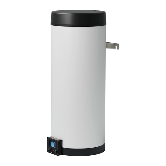
Domestic hot water tank
Hide thumbs
Also See for EKHWET90B V3 Series:
- Installer's reference manual (120 pages) ,
- User reference manual (52 pages) ,
- Operation manual (16 pages)
Table of Contents
Advertisement
Quick Links
Advertisement
Table of Contents

Related Manuals for Daikin EKHWET90B V3 Series


Summary of Contents for Daikin EKHWET90B V3 Series
- Page 1 Installation manual R32 Split series – Domestic hot water tank https://daikintechnicaldatahub.eu EKHWET90B▲V3▼ EKHWET120B▲V3▼ Installation manual English ▲= 1, 2, 3, …, 9, A, B, C, …, Z R32 Split series – Domestic hot water tank ▼= , , 1, 2, 3, …, 9...
- Page 2 4P680418-1...
-
Page 3: Table Of Contents
Configuration wizard: Language ......... 14 Daikin website (publicly accessible). 7.2.2 Configuration wizard: Time and date ......14 ▪ The full set of latest technical data is available on the Daikin 7.2.3 Configuration wizard: System ........15 Business Portal (authentication required). -
Page 4: Specific Installer Safety Instructions
Make sure installation, servicing, maintenance and repair cable. comply with instructions from Daikin and with applicable INFORMATION legislation and are executed ONLY by authorised persons. Details of type and rating of fuses, or rating of circuit Opening and closing the unit (see "4.2 Opening and closing the... -
Page 5: Indoor Unit
(example: open Make sure installation, servicing, maintenance and repair flames, an operating gas appliance or an operating electric comply with instructions from Daikin and with applicable heater). legislation and are executed ONLY by authorised persons. WARNING... -
Page 6: Installation Patterns
4 Unit installation 4.1.3 Installation patterns Depending on the type of room in which you install the indoor unit, different installation patterns are allowed: Room type Allowed patterns Living room, kitchen, garage, attic, basement, storage room 1, 2 Technical room (i.e. room that is NEVER occupied by persons) 1, 2, 3 PATTERN 1 PATTERN 2... - Page 7 4 Unit installation PATTERN 2 PATTERN 2: Conditions ventilation openings If you want to take advantage of the floor area of the adjacent room, you must provide 2 openings (one at the bottom, one at the top) between the rooms to ensure natural ventilation.
- Page 8 4 Unit installation Tables for PATTERN 1 and 2 Table 1: Minimum floor area Take the following into account: • For intermediate floor areas, use the column with the lower value. Example: If the floor area is 1.7 m², use the column of 1.65 m². •...
-
Page 9: Opening And Closing The Unit
4 Unit installation (dm²) – In case of Refrigerant charge=2.6 kg nv-min Release height (m) Floor area of room A (m²) [! NOT room A + room B !] 2,00 4,00 6,00 8,00 10,00 12,00 14,00 2.65 PATTERN 3 PATTERN 3 is only allowed for installations in technical rooms (i.e. Opening and closing the unit room that is NEVER occupied by persons). -
Page 10: Mounting The Indoor Unit
5 Piping installation Mounting the indoor unit 4.3.1 To install the indoor unit 1 Install 2 plugs into the wall and insert (but not completely) 2 bolts with washers into the plugs. Piping installation 2× Preparing refrigerant piping 5.1.1 Refrigerant piping requirements ▪... -
Page 11: Preparing Water Piping
6 Electrical installation 2 Install the following components (field supply) on the cold water Preparing water piping inlet of the DHW tank: NOTICE In case of plastic pipes, make sure they are fully oxygen diffusion tight according to DIN 4726. The diffusion of oxygen into the piping can lead to excessive corrosion. -
Page 12: Connections To The Indoor Unit
6 Electrical installation Item Tightening torque (N•m) 2.45 ±10% 0.88 ±10% 2.45 ±10% M4 (earth) 1.47 ±10% Connections to the indoor unit Item Description Power supply (main) "6.3.1 To connect the main power supply" [ 4 12]. Power supply (booster "6.3.2 To connect the booster heater supply" [ 4 12]. -
Page 13: To Connect The Wlan Cartridge (Delivered As Accessory)
7 Configuration Configuration Overview: Configuration This chapter describes what you have to do and know to configure the system after it is installed. NOTICE This chapter explains only the basic configuration. For more detailed explanation and background information, see the installer reference guide. If you do NOT configure the system correctly, it might NOT work as expected. -
Page 14: Configuration Wizard
7 Configuration 1 Go to [B]: User profile. 3 Turn the left dial to select the first part of the setting and confirm by pressing the dial. User profile 2 Enter the applicable pin code for the user permission — 4 Turn the left dial to select the second part of the level. -
Page 15: Configuration Wizard: System
7 Configuration Settings for Reheat only mode 7.2.3 Configuration wizard: System During Reheat only mode, the tank setpoint can be set on the user Indoor unit type interface. The maximum allowed temperature is determined by the following setting: The indoor unit type is displayed, but cannot be adjusted. Code Description Domestic hot water... -
Page 16: Weather-Dependent Curve
7 Configuration Example INFORMATION To ensure most optimum operation of the outdoor unit, we recommend to set the hysteresis to 6°C or higher. INFORMATION If Reheat setpoint is outside operation range of the outdoor unit, then the hysteresis will refer to the the highest temperature achievable by heat pump operation. -
Page 17: Using Weather-Dependent Curves
7 Configuration INFORMATION Maximum and minimum setpoints You cannot configure the curve with temperatures that are higher or lower than the set maximum and minimum setpoints for the tank. When the maximum or minimum setpoint is reached, the curve flattens out. To fine-tune the weather-dependent curve: slope-offset curve The following table describes how to fine-tune the weather- dependent curve of the tank:... -
Page 18: Menu Structure: Overview Installer Settings
7 Configuration Menu structure: Overview installer settings [9] Installer settings [9.4] Booster heater Capacity Configuration wizard Quick mode timer Booster heater Operation Emergency Power consumption control Auto restart [9.5] Emergency Power saving function Emergency Disable protections Overview field settings Export MMI settings [9.9] Power consumption control Power consumption control Type... -
Page 19: Commissioning
The correct pipe size is installed and the pipes are commissioning instructions in this chapter, a general properly insulated. commissioning checklist is also available on the Daikin Business Portal (authentication required). There is NO water leak inside the indoor unit. -
Page 20: Hand-Over To The User
9 Hand-over to the user 4 Select OK to confirm. Result: The actuator test run starts. It stops automatically when ready (±30 min). To stop the test run manually: — 1 In the menu, go to Stop test run. 2 Select OK to confirm. Possible actuator test runs ▪... -
Page 21: Technical Data
10 Technical data Technical data A subset of the latest technical data is available on the regional Daikin website (publicly accessible). The full set of latest technical data is available on the Daikin Business Portal (authentication required). 10.1 Piping diagram: Indoor unit 3D138207 Domestic hot water –... -
Page 22: Wiring Diagram: Indoor Unit
10 Technical data 10.2 Wiring diagram: Indoor unit See the internal wiring diagram supplied with the unit (on the inside of the indoor unit switch box cover). The abbreviations used are listed below. Legend Main PCB Note 1: Connection point of the Note 1: Connection point of the power supply for the BSH should power supply for the booster... - Page 23 10 Technical data Electrical connection diagram For more details, please check the unit wiring. STANDARD PART Power supply OUTDOOR UNIT Only for normal power supply installation 3 core unit power supply: 230 V + earth X1M: L-N-earth Only for preferential kWh rate power supply installation unit preferential kWh rate power supply: 3 core 230 V + earth...
- Page 24 4P680074-1 C 0000000/ 4P680074-1C 2022.11 Verantwortung für Energie und Umwelt...
Need help?
Do you have a question about the EKHWET90B V3 Series and is the answer not in the manual?
Questions and answers