Table of Contents
Advertisement
Quick Links
FES MOTOR MANUAL
This manual is accepted by DG Aviation as manual for the
motor FES-DG-M100, if used in the DG-1001E.
Issued
LZ Design
(DE/EI)
Date
Nov. 2022
LZ design d.o.o., Brod 3D, 1370 Logatec, Slovenia tel +386 59 948 898
Type:
Checked
(CVE/MPI)
Date
info@lzdesign.si
Version 1.0
FES-DG-M100
Wassenaar
16 .Nov. 2022
www.front-electric-sustainer.com
Dirks
Approved
(HoOA/LMPL)
Date
16. Nov. 2022
Advertisement
Table of Contents

Related Manuals for LZ design FES-DG-M100


Summary of Contents for LZ design FES-DG-M100
- Page 1 FES-DG-M100, if used in the DG-1001E. Wassenaar Dirks Issued Checked Approved LZ Design (DE/EI) (CVE/MPI) (HoOA/LMPL) Date Nov. 2022 Date 16 .Nov. 2022 Date 16. Nov. 2022 LZ design d.o.o., Brod 3D, 1370 Logatec, Slovenia tel +386 59 948 898 info@lzdesign.si www.front-electric-sustainer.com...
-
Page 2: Table Of Contents
Table of Content 1. Important notices ..................... 3 1.1 Limited Warranty ....................3 2. General ........................4 3. Model designation ....................4 4. Technical data and limitations of motor ..............5 5. Drawing of motor ..................... 6 6. Maintenance ......................7 7. -
Page 3: Important Notices
LZ design retains the exclusive right to repair or replace the unit or software, or to offer a full refund of the purchase price, at its sole discretion. SUCH REMEDY SHALL BE YOUR SOLE AND EXCLUSIVE REMEDY FOR ANY BREACH OF WARRANTY. -
Page 4: General
Motor identification numbers are laser engraved into rear Aluminium plate of motor. NOTE: Motor type FES-DG-M100 is very similar like all other versions of FES-M100 motors. Main difference between is due to shape of front torsional plate, which is adjusted to different shape of spinner. -
Page 5: Technical Data And Limitations Of Motor
DC current from battery packs to 3 phase current which supply motor. We use controller type which needs hall position sensors in motor, but this motor can work also with some sensorless controllers. Electrical motor type FES-DG-M100 technical specifications: 75Nm Maximum torque... -
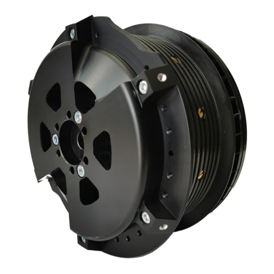
Page 6: Drawing Of Motor
5. Drawing of motor... -
Page 7: Maintenance
6. Maintenance The motor does not need any maintenance. Opening or disassembling of the motor would cause a forfeit of warranty claims! It could be also very dangerous, due to very strong magnets on rotor! Though, it must be considered that no foreign objects at all can enter the interior of the drive. -
Page 8: Removal Of Motor
7. Removal of motor Removal of motor from sailplane is only allowed in case of written Note: permission from manufacturer otherwise warranty is not valid anymore! It is not allowed to fly with removed motor from the sailplane, as Warning: C.G. - Page 9 2. Remove pitot tube assembly which is fixed on the back side of motor mounting plate. To do that is necessary to unscrew two M5 bolts on top. Then carefully pull- out pitot tube assembly. 3. Unlock two spring-locks which hold DB15 cable connector. Carefully unplug connector from the socket of motor rear wall.
-
Page 10: Installation Of Motor
8. Installation of motor To install motor back on glider, follow the reverse order of previous chapter. Take care about additional steps: 1. Below M8 motor fixation bolts, it is recommended to use new brass safely spacers 2. Make sure that power cables are connected in the same order as before (check your photo for reference). -
Page 11: Repair And Service
9. Repair and service In case of a fault or damage, please contact manufacturer. 10. Revision history November 2022 Initial release of manual, v1.0...
Need help?
Do you have a question about the FES-DG-M100 and is the answer not in the manual?
Questions and answers