ReadyNet LTE520S User Manual
Hide thumbs
Also See for LTE520S:
- Quick installation manual (2 pages) ,
- Quick installation manual (2 pages)

Related Manuals for ReadyNet LTE520S


Summary of Contents for ReadyNet LTE520S
- Page 1 User Manual LTE520S Manual Version: V3.20221213 Firmware Version: V3.36_202211140613...
-
Page 2: Table Of Contents
Table of Contents Table of Contents About This User Guide ........................... 1 Contacting ReadyNet ........................2 Purpose ............................. 3 Cross References ..........................3 Feedback ............................3 Declaration of Conformity ........................4 Part 15 FCC Rules ..........................4 Warnings and Notes ..........................5 Warnings ............................ - Page 3 Table of Contents FXS1 ................................. 75 FXS2 ................................. 85 Security ..............................86 Application .............................. 89 Administration ............................91 Management ..........................91 Firmware Upgrade .......................... 96 Scheduled Tasks ..........................97 Provision ............................98 SNMP ............................100 TR-069 ............................101 Diagnosis ............................103 Operating Mode ...........................
- Page 4 Table of Contents Tables Table 1 Features At-a-Glance ..........................7 Table 2 LED Indicators ............................8 Table 3 Interfaces ..............................9 Table 4 Voice Menu Setting Options ........................12 Table 5 Web Management Interface ........................20 Table 6 Setting Time Zone ........................... 21 Table 7 Configuring an Internet Connection ......................
- Page 5 Table of Contents Table 35 WPA-PSK ..............................59 Table 36 WPAPSKWPA2PSK ..........................59 Table 37 Wireless Access Policy .......................... 60 Table 38 WMM ..............................61 Table 39 WDS ............................... 62 Table 40 WPS ............................... 63 Table 41 Station Info ............................64 Table 42 Advanced ...............................
- Page 6 Table of Contents Table 76 Diagnosis .............................. 103 Table 77 Operating mode ..........................105 Table 78 System log ............................106 Table 79 Logout & Reboot ..........................106...
-
Page 7: About This User Guide
LTE520S wireless router to the Internet. Before you can connect the LTE520S to the Internet and use it, you must have a high-speed broadband connection installed or an LTE sim card. A high-speed connection is usually provided via DSL, cable modem, fiber, or other broadband service. -
Page 8: Contacting Readynet
About This User Guide Contacting ReadyNet Web: https://www.readynetsolutions.com Main Phone Line: +1 (801) 566-0100 Sales Department: +1 (801) 984-5133, +1 (801) 984-5130 Customer Service: +1 (801) 566-0100, Option 1 Service Provider Support: +1 (855) 671-7932 Sales: sales@readynetsolutions.com Customer Support: customerservice@readynetsolutions.com Service Provider Technical Support: engineering@readynetsolutions.com... -
Page 9: Purpose
This document is intended to instruct and assist users in the operation, installation and maintenance of ReadyNet’s LTE520S router. It is recommended that all users engaged in such activities be properly trained in technical router operations. ReadyNet disclaims all liability whatsoever, implied or... -
Page 10: Declaration Of Conformity
About This User Guide Declaration of Conformity Part 15 FCC Rules This device complies with Part 15 of the FCC Rules. Operation is subject to the following two conditions: • This device may not cause harmful interference, and • This device must accept any interference received, including interference that may cause undesired operation. -
Page 11: Warnings And Notes
Notes text and consequences for not following the instructions in the Notes. GNU GPL Information ReadyNet firmware contains third-party software under the GNU General Public License (GPL). Please refer to the GPL for the exact terms and conditions of the license. See links below for important regulatory information. -
Page 12: Chapter 1: Product Description
Chapter 1 Product Description Chapter 1: Product Description This chapter covers: · LTE520S · LED Indicators and Interfaces · Hardware Installation · Voice Menu... -
Page 13: Lte520S
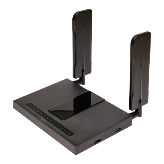
Chapter 1 Product Description LTE520S Table 1 Features At-a-Glance Port/Model LTE520S Picture Ethernet 5* RJ45 Interface 10/100M T.30, T.38 Fax Wi-Fi 2.4G 2T2R (300Mbps) G.711 (A-law, U-law), G.729A/B, G.723, G.722 (Wide band) Voice Code Management Voice Menu, Web Management, Provision: TFTP/HTTP/HTTPS, TR069, SNMP... -
Page 14: Led Indicators And Interfaces
Chapter 1 Product Description LED Indicators and Interfaces Table 2 LED Indicators LTE520S Status Explanation on Green System is powered on Power System is powered off on Green System runs normally System Blinking Green System trouble System is powered off... -
Page 15: Table 3 Interfaces
Chapter 1 Product Description Table 3 Interfaces LTE520S Interface Description POWER Connection port for the power adapter PHONE 1/2 FXS ports (ATA) for analog telephone connections LAN 1/2/3/4 Connection ports for local wired networked devices Connection port for accessing the Internet via a wired connection RESET Button to restore the router to factory settings. - Page 16 Chapter 1 Product Description Hardware Installation Before configuring your router, please see the procedures below for instructions on connecting the device to your network. Procedure 1 Configuring the Router 1. If you wish to use ATA functionality, connect an analog phone line to one of the FXS ports with an RJ11 cable (provided).
- Page 17 Chapter 1 Product Description Warning Changes or modifications not expressly approved by the party responsible for compliance will void the user's authority to operate the equipment. This equipment has been tested and found to comply with the limits for a Class B digital device, pursuant to Part 15 of the FCC Rules.
-
Page 18: Voice Menu
Chapter 1 Product Description Voice Menu The device may be configured by navigating the unit's Voice Menu. By using your phone and dialing a sequence of commands, the device may be configured for operation. Each device configuration section may be accessed by entering a certain operation code, as shown below: Table 4 Voice Menu Setting Options Operation Menu Navigation... - Page 19 Chapter 1 Product Description 1. Pick up the phone and press "****" to start IVR. 2. Choose "2", and the router will report its current WAN port IP address. 3. Input the new WAN port IP address and press the "#" key: 4.
- Page 20 Chapter 1 Product Description 1. Pick up the phone and press "****" to start IVR. 2. Choose "5", and the router will report its current DNS. 3. Input the new DNS and press the “#” key: 4. Use "*" to replace ".", for example, the user can input 192*168*20*1 to set the new DNS to 192.168.20.1 5.
- Page 21 Chapter 1 Product Description 1. Pick up the phone and press "****" to start IVR. 2. Choose "8", and the router will report "WAN port login". 3. Prompt: "Please enter password", the method of inputting the password is the WAN Port same as in Operation (1).
- Page 22 DHCP server is available in your existing broadband connection to which the WAN port of the LTE520S is connected. 6. The default LAN port IP address of the LTE520S router is 192.168.11.1. This address should not be assigned to the WAN port IP address of the LTE520S in the same network segment.
-
Page 23: Chapter 2: Configuring Basic Settings
Chapter 2: Configuring Basic Settings This chapter covers: • Two-Level Management • Web Management Interface • Configuring SIP • Making a Call... -
Page 24: Two-Level Management
For user mode operation, please enter the Username/Password found on the label on the bottom of the router and click Login to begin configuration. Web Management Interface The LTE520S features a web-based interface that may be used to configure and manage the device. See below for additional information: Logging in from the LAN port 1. - Page 25 Chapter 2 Configuring Basic Settings 3. To access the web management interface, please enter the Username/Password as previously discussed and click Login to begin configuration. Note If you are unable to access the web management interface, please see the Chapter 4: Troubleshooting Guide for more information.
-
Page 26: Web Management Interface Details
Chapter 2 Configuring Basic Settings Web Management Interface Details Table 5 Web Management Interface Field Name Description Top Navigation Bar Click an option in the top navigation bar (area marked as "1"). Multiple options in the sub navigation bar are displayed. Sub Navigation Bar Click the sub navigation bar to choose a configuration page (area marked as "2"). -
Page 27: Setting The Time Zone
Chapter 2 Configuring Basic Settings After changing the parameters on a given page, the user needs to click the “Save & Apply” button. After clicking, the new parameters immediately take effect. Anytime changes are made on a page, click "Save" to confirm and save the changes. Once clicking the "Save"... -
Page 28: Configuring An Internet Connection
Chapter 2 Configuring Basic Settings Configuring an Internet Connection From the Network > WAN page, WAN connections may be inserted or deleted. For more information on Internet Connection setting, see Table 7 below: Table 7 Configuring an Internet Connection Field Name Description Connect Name Describes the WAN port service mode as defined. - Page 29 Chapter 2 Configuring Basic Settings VLAN Mode Enables or disables VLAN Mode or allows trunk mode. VLAN ID Note Multiple WAN connections may be created with the same VLAN ID DNS Mode Selects the DNS mode, options are Auto and Manual: When DNS mode is Auto, the device under the LAN port will automatically obtain the primary DNS and the secondary DNS.
-
Page 30: Setting Up Wireless Connections
Chapter 2 Configuring Basic Settings Setting up Wireless Connections To set up the wireless connection, please perform the following steps. Enable Wireless and Setting SSID Navigate to Wireless > Basic page as shown below: Table 8 Wireless > Basic (user view) Field Name Description Select "Radio Off"... - Page 31 Chapter 2 Configuring Basic Settings Enable: The device SSID is broadcast at regular intervals. Disable: The device SSID is not broadcast at regular intervals, disallowing broadcast(SSID) Wi-Fi clients from automatically discovering the Wi-Fi network. Enable: Devices connected to the router are isolated from one another on virtual AP Isolation networks.
-
Page 32: Table 9 Wireless Security Page
Chapter 2 Configuring Basic Settings Encryption Open the Wireless > Wireless Security page to configure custom security parameters. Table 9 Wireless Security Page Field Name Description SSID Choice Choose the SSID from the drop-drown list for which security will be configured Select an appropriate encryption mode to improve the security and privacy of your wireless data packets. -
Page 33: Configuring Session Initiation Protocol (Sip)
Chapter 2 Configuring Basic Settings Configuring Session Initiation Protocol (SIP) SIP Accounts The device has 2 FXS phone ports to make SIP (Session Initiation Protocol) calls. Before registering, the device user should have a SIP account configured by the system administrator or provider. See the section below for more information: Configuring SIP via the Web Management Interface Table 10 Configuring SIP via the Web Management Interface... -
Page 34: Table 11 Registration Status
Chapter 2 Configuring Basic Settings Viewing the Registration Status Table 11 Registration Status Procedure Open the main Status page and scroll down to view the SIP Account Status. -
Page 35: Making A Call
Chapter 2 Configuring Basic Settings Making a Call Calling Phone or Extension Numbers To make a phone or extension number call: 1. Both the ATA and the other VoIP device (i.e., another ATA or other SIP product) must have public IP addresses, OR 2. - Page 36 Chapter 2 Configuring Basic Settings Blind Transfer Assume that call party A and party B are in a conversation and that party A wants to Blind Transfer B to C: Party A dials "*78" to get a dial tone, then dials party C's number, and then immediately presses “#” (or wait for 4 seconds) to dial out.
- Page 37 Chapter 3: Web Management Interface This chapter guides users to execute advanced (full) configuration through admin mode operation. This chapter covers: 4. Login 5. Status 6. Network and Security 7. Wireless 8. SIP 9. FXS1 10. FXS2 11. Security 12. Application 13.
-
Page 38: Chapter 3 Web Management Interface
Chapter 3 Web Management Interface Login Table 12 Login details Procedure 1. Connect the LAN port of the router to your PC via an ethernet cable. 2. Open a web browser on your PC and type http://192.168.11.1 3. Enter the Username/Password as provided. 4. -
Page 39: Status
Chapter 3 Web Management Interface Status Table 13 Status Page... - Page 40 Chapter 3 Web Management Interface...
- Page 41 Chapter 3 Web Management Interface Description This page shows the status information about the Product, Network, and System including Product Information, SIP Account Status, FXS Port Status, Network Status. Wireless Info and System Status...
-
Page 42: Network And Security
Chapter 3 Web Interface Network and Security You can configure the WAN port, LAN port, DDNS, Multi WAN, DMZ, Port Forward and other parameters in this section of the web management interface. This page allows you to set WAN configuration with different modes. Use the drop-down lists to choose WAN parameters and then the corresponding page will be displayed. - Page 43 Chapter 3 Web Interface Default Gateway The default gateway of the Internet port. DNS Mode Select DNS mode, options are Auto and Manual: 1. When DNS mode is Auto, the device under the LAN port will automatically obtain the preferred DNS and the alternate DNS. 2.
- Page 44 Chapter 3 Web Interface Field Name Description DNS Mode Select DNS mode, options are Auto and Manual: 1. When DNS mode is Auto, the device under the LAN port will automatically obtain the preferred DNS and the alternate DNS. 2. When DNS mode is in Manual, the user manually configures the preferred DNS and alternate DNS information.
- Page 45 Chapter 3 Web Interface Field Name Descriptio PPPoE Account Enter a valid username provided by the ISP. PPPoE Password Enter a valid password provided by the ISP. The password can contain special characters and allowed special characters are $, +, *, #, @ and ! For example, the password can be entered as #net123@IT!$+*.
-
Page 46: Table 17 Bridge Mode
Chapter 3 Web Interface Table 17 Bridge Mode Field Name Description Bridge Type IP Bridge Allow all ethernet packets to pass. PC can connect to upper network directly. PPPoE Bridge Only allow PPPoE packets to pass. PC needs PPPoE dial-up software. Hardware IP Bridge Packets pass through the hardware switch with wired speed. -
Page 47: Lte
Chapter 3 Web Interface VLAN Mode The WAN interface is untagged. LAN is untagged. Disable The WAN interface is tagged. LAN is untagged. Enable Trunk Only valid in bridge mode. All ports, including WAN and LAN, belong to this VLAN ID and all ports are tagged with this VLAN ID. - Page 48 Chapter 3 Web Interface Field Name Description Basic Setting Enable LTE Modem Enable the LTE Modem. Enable GSM Call Enable the GSM Call. 4G Connection Type Choose the 4G connection method, Auto or Manual. APN Mode Choose the APN Mode, Auto or Manual. Enter the APN.
-
Page 49: Lan
Chapter 3 Web Interface LAN Port NAT translates the packets from public IP addresses to local IP addresses to forward packets to the proper destination. Table 19 LAN port Field Name Description IP Address Enter the IP address of the router on the local area network. All the IP addresses of the computers which are in the router's LAN must be in the same network segment with this address, and the default gateway of the computers must be this IP address. - Page 50 Chapter 3 Web Interface DHCP Start Address Enter a valid IP address as a starting IP address of the DHCP server. For example, if the router's LAN IP address is 192.168.11.1, the starting DHCP IP address should be 192.168.11.2 or greater. DHCP End Address Enter a valid IP address as an end IP address of the DHCP server.
-
Page 51: Table 20 Dhcp Server Settings
Chapter 3 Web Interface DHCP Server The router has a built-in DHCP server that assigns private IP addresses to each local client. DHCP stands for Dynamic Host Configuration Protocol. The router, by factory default acts a DHCP server for your network so it automatically dispatches related IP settings to any local user configured as a DHCP client. -
Page 52: Table 21 Dhcp Server, Dns And Client Lease Time
Chapter 3 Web Interface Table 21 DHCP server, DNS and Client Lease Time Field Name Description Primary DNS Enter the primary DNS address. Secondary DNS Enter the secondary DNS address. Client Lease Time This option defines how long the DHCP IP address will be assigned to a client within the network. -
Page 53: Table 23 Port Forward
Chapter 3 Web Interface Port Forward Table 23 Port Forward Field Name Description Comment Sets the name of a port mapping rule or comment. IP Address Enter the IP address of the desired device. Port Range Set the port range for the device. (1-65535) Protocol You can select TCP, UDP, or TCP &... -
Page 54: Table 24 Dmz
Chapter 3 Web Interface Table 24 DMZ Field Name Description DMZ Enable Enable/Disable DMZ. DMZ Host IP Address Enter the private IP address of the DMZ host. DDNS Table 25 DDNS Field Name Description Dynamic DNS Provider Enable DDNS and select a DDNS service provider. Account Fill in the DDNS service account. -
Page 55: Table 26 Qos
Chapter 3 Web Interface Table 26 QoS Field Name Description Enable QoS Enable/disable QoS function. Upstream Set the upstream bandwidth. Downstream Set the downstream bandwidth. Algorithm Choose an Algorithm. Delete Selected In NO., Check the items you want to delete, click the Delete Selected button. Click Add to add a new parameter. -
Page 56: Table 27 Mac Clone
Chapter 3 Web Interface MAC Clone Some ISPs will require you to register your MAC address. If you do not wish to re-register your MAC address, you can have the router clone the MAC address that is registered with your ISP. 1. -
Page 57: Table 28 Port Setting
Chapter 3 Web Interface Port Setting Table 28 Port setting Field Name Description WAN Port Speed Nego Auto-negotiation, options are Auto, 100M full, 100M half-duplex, 10M half and full. LAN1-LAN4 Port Speed Nego Auto-negotiation, options are Auto, 100M full, 100M half-duplex, 10M half and full. -
Page 58: Table 30 Advance
Chapter 3 Web Interface Field Name Description Destination Enter the destination address. Host/Net Choose Host or Net selection. Gateway Enter the gateway IP address. Interface Select the interface—options are LAN, VOICE, TR069, and VPN. Comment Comment Advance Table 30 Advance Field Name Description Most Nat connections... -
Page 59: Table 31 Connection Manager
Chapter 3 Web Interface Connection Manager Table 31 Connection Manager For more detailed instructions, please see the Connection Manager Instructions found in Appendix... -
Page 60: Wireless
Chapter 3 Web Interface Wireless Basic Table 32 Basic Field Name Description Radio on/off Select "Radio Off" to disable wireless. Select "Radio On" to enable wireless. Wireless Connection Mode According to the wireless client type, select one of these modes. Default is AP. Network Mode Choose one network mode from the drop-down list. - Page 61 Chapter 3 Web Interface SSID The SSID is the name of the Wi-Fi network. The SSID can be alphanumeric or a combination of special characters. It will appear in the wireless network access list. Multiple SSID1~SSID3 The device supports 4 SSIDs. Hidden After the item is checked, the SSID is no longer displayed in the search for the Wi-Fi wireless network connection list.
- Page 62 Chapter 3 Web Interface Enabled: Multiple copies of signals are transmitted to increase the chance of successful delivery. Aggregation MSDU (A- Enabled: Allows the device to aggregate multiple ethernet frames into a single Disabled: STBC is not employed for signal transmission MSDU) 802.11n, thereby improving the ratio of frame data to frame overhead.
-
Page 63: Table 33 Wireless Security
Chapter 3 Web Interface Wireless Security Table 33 Wireless Security Field Name Description SSID Choice Choose one SSID from SSID, Multiple SSID1, Multiple SSID2 and Multiple SSID3. Select an appropriate encryption mode to improve the security and privacy of your wireless data packets. -
Page 64: Table 34 Wi-Fi Security Setting
Chapter 3 Web Interface The user can configure the corresponding parameters. Here are some common encryption methods: OPENWEP: A handshake way of WEP encryption, encryption via the WEP key: Table 34 Wi-Fi Security Setting Field Name Description Security Mode This is used to select one of the 4 WEP keys, key settings on the clients should be the same as this when connecting. - Page 65 Chapter 3 Web Interface WPA-PSK: The router will use the WPA-PSK encryption method, which is based on the concept of a pre-shared key. Table 35 WPA-PSK Field Name Description WPA Algorithms This item is used to select the encryption of wireless home gateway algorithms, options are TKIP, AES and TKIPAES.
- Page 66 Chapter 3 Web Interface WPA-PSK/WPA2-PSK WPA/WPA2 security type is actually a simplified version, which is based on the WPA shared key mode. The higher security setting is also relatively simple, suitable for ordinary home users and small businesses. Wireless Access Policy: Table 37 Wireless Access Policy Field Name Description...
- Page 67 Chapter 3 Web Interface Table 38 WMM Description WMM (Wi-Fi Multi-Media) is the QoS certificate of Wi-Fi Alliance (WFA). This provides you with the opportunity to configure the parameters of wireless multimedia; WMM allows wireless communication to define a priority according to the home gateway type. To make WMM effective, the wireless clients must also support WMM.
- Page 68 Chapter 3 Web Interface Table 39 WDS Description WDS stands for Wireless Distribution System, enabling WDS access points to be interconnected to expand a wireless network. WPS (Wi-Fi Protected Setup) provides an easy procedure to make network connections between a wireless device and a wireless access point with the encryption of WPA and WPA2.
- Page 69 Chapter 3 Web Interface Table 40 WPS Field Name Description WPS Config Enable/Disable WPS function. WPS Summary WPS Current Status Displays the current status of WPS. Displays the configuration status of WPS. WPS Configured WPS SSID Displays WPS SSID. WPS Progress WPS Mode PIN: Enter the PIN code of the wireless device which accesses to this LAN in the following option, and press apply.
- Page 70 Chapter 3 Web Interface WPS Status WPS shows status in three ways: WSC: Idle WSC: Start WSC process (begin to send messages) WSC: Success; this means clients have accessed the AP successfully Station Info Table 41 Station Info Description This page displays information about the current registered clients' connections including operating MAC address and operating statistics.
- Page 71 Chapter 3 Web Interface Advanced Table 42 Advanced Field Name Description BG Protection Mode Select G protection mode, options are on, off and automatic. Beacon Interval The interval of sending a wireless beacon frame, within this range, it will send a beacon frame for the information of the surrounding radio network.
- Page 72 Chapter 3 Web Interface RTS Threshold Specify the packet RTS threshold, when the packet exceeds this value, the router will send RTS to the destination site consultation. TX Power Define the transmission power of the current AP, the greater it is, the stronger the signal.
-
Page 73: Sip
Chapter 3 Web Interface SIP Settings Table 43 SIP Settings Field Name Description SIP T1 The minimum scale of retransmission time. Max Forward SIP contains Max Forward message header fields used to limit the requests for forwards. SIP Reg User Agent Name The agent name of the SIP registered user. - Page 74 Hold Service Type Choose the server type. NAT Traversal Disables NAT Traversal or enables STUN. The LTE520S supports STUN Traversal; if user wants to traverse NAT/Firewall, select the STUN. STUN Server Add the correct STUN service provider IP address. Address NAT Refresh Set NAT Refresh Interval, default is 60s.
- Page 75 Chapter 3 Web Interface Dial Rule Parameters and Settings Table 45 Parameters and Settings Field Name Description Dial Rule Enable/Disable dial rule. Set the FXS. Digit Map Enter the sequence used to match the input number. For the syntactic, please refer to the following Dial Rule Syntactic. Action Choose the dial plan mode from Deny and Dial Out.
- Page 76 Chapter 3 Web Interface Adding One Dial Rule Table 46 Adding One Dial Rule Description Step 1. Enable Dial Rule. Step 2. Click the Add button, and the configuration table will appear. Step 3. Fill in parameters. Step 4. Click the OK button to add configuration.
- Page 77 Chapter 3 Web Interface Dial Rule Syntactic Table 47 Dial Rule String Description 0 1 2 3 4 5 6 7 8 9 * # Allowed characters Lowercase letter "x" stands for one legal character To match one character form sequence. For example: [sequence] [0-9]: match one digit from 0 to 9 [23-5*]: match one character from 2 or 3 or 4 or 5 or *...
-
Page 78: Blacklist
Chapter 3 Web Interface Blacklist Here the user can upload or download blacklist a file or can add, delete or edit blacklist entries individually. Table 48 Blacklist Description Click Choose File to select the blacklist file and Upload CSV to upload it to device; Click Download CSV to save the blacklist file to your local computer. - Page 79 Chapter 3 Web Interface Call Log The call log enables the user to view information such as the redial list, answered calls and missed calls. Table 49 Call Log...
- Page 80 Chapter 3 Web Interface...
-
Page 81: Fxs1
Chapter 3 Web Interface FXS1 SIP Account Basic Set the basic information provided by your VOIP Service Provider, such as Phone Number, Account, password, SIP Proxy and others. Table 50 SIP Account - Basic Field Name Description Line Enable Enable/Disable the line. Enable/Disable PEER to PEER. - Page 82 Chapter 3 Web Interface Outbound Port Outbound Proxy's Service port, default is 5060 Backup Outbound Port Backup Outbound Proxy's Service port, default is 5060 Display Name The number will be displayed on LCD Phone Number Enter telephone number provided by SIP Proxy Account Enter SIP account provided by SIP Proxy Password...
- Page 83 Chapter 3 Web Interface Auto Gain Control Enable/Disable auto gain T.38 Enable Enable/Disable T.38 T.38 Redundancy Enable/Disable T.38 Redundancy T.38 CNG Detect Enable Enable/Disable T.38 CNG Detect gpmd attribute Enable Enable/Disable gpmd attribute. Supplementary Service Subscription Table 52 Supplementary service Field Name Description Call Waiting...
- Page 84 Chapter 3 Web Interface Voice Mailbox Fill in the voice mailbox phone number, Asterisk platform, for example, its default voice Numbers mail is *97 VMWI Serv Enable/Disable VMWI service Enable/Disable DND (do not disturb) If enable, any phone call cannot arrive at the device; default is disable Enter the speed dial phone numbers.
- Page 85 Chapter 3 Web Interface Field Name Description Domain Name Type If or not use domain name in the SIP URI. Carry Port Information If or not carry port information in the SIP URI. Signal Port The local port of SIP protocol, default is 5060. DTMF Type Choose the DTMF type from Inbound, RFC2833 and SIP INFO.
- Page 86 Chapter 3 Web Interface Dial Prefix The number will be added before your telephone number when making calls. User Type Choose the User Type from IP and Phone. Hold Method Choose the Hold Method from ReINVITE and INFO. Request-URI User Check Enable/Disable the user request URI check.
- Page 87 Chapter 3 Web Interface Regional Table 55 Regional Field Name Description Tone Type Choose tone type form China, US, Hong Kong and so on Dial Tone Dial Tone Busy Tone Busy Tone Off Hook Warning Tone Off Hook warning tone Ring Back Tone Ring back tone Call Waiting Tone...
- Page 88 Chapter 3 Web Interface Features and Call Forward Table 56 Features and call forward Field Description Name All Forward Enable/Disable forward all calls Features Busy Forward Enable/Disable busy forward. No Answer Forward Enable/Disable no answer forward. All Forward Set the target phone number for all forward. Call The device will forward all calls to the phone number immediately Forward...
- Page 89 Chapter 3 Web Interface Transfer key code Call forwarding signatures, default is *98. IVR key code Signatures of the voice menu, default is ****. R key enable Enable/Disable R key way call features. R key cancel code Set the R key cancel code, options are ranged from R1 to R9, default value is R1.
- Page 90 Chapter 3 Web Interface Miscellaneous Table 57 Miscellaneous Field Name Description Codec Loop Current Set off-hook loop current, default is 26. Impedance Matching Set impedance matching, default is US PBX, Korea, Taiwan(600). CID service Enable/Disable displaying caller ID; If enable, caller ID is displayed when there is an incoming call or it won't be displayed.
-
Page 91: Fxs2
Chapter 3 Web Interface FXS2 The settings of FXS2 are the same as FXS1. See FXS1 on page 76. -
Page 92: Security
Chapter 3 Web Interface Security Filtering Setting Table 58 Filtering Setting Field Name Description Filtering Enable/Disable filter function Default Policy Choose to drop or accept filtered MAC addresses Mac address Add the Mac address filtering Dest IP address Destination IP address Source IP address Source IP address Protocol... - Page 93 Chapter 3 Web Interface Content Filtering Table 59 Content Filtering...
- Page 94 Chapter 3 Web Interface Field Name Description Filtering Enable/Disable content Filtering Default Policy The default policy is to accept or to prohibit filtering rules Current Webs URL Filters List the URL filtering rules that already existed (blacklist) Delete/Cancel You can choose to delete or cancel the existing filter rules Add a URL Filter Add URL filtering rules Add/Cancel...
-
Page 95: Application
Chapter 3 Web Interface Application Advance NAT Table 60 advance NAT Enable/Disable these function(FTP/SIP/H323/PPTP/L2TP/IPSec). UPnP UPnP (Universal Plug and Play) supports zero-configuration networking, and can automatically discover a variety of networked devices. When UPnP is enabled, the connected device is allowed to access the network, obtain an IP address, and convey performance information. - Page 96 Chapter 3 Web Interface IGMP Multicast has the ability to send the same data to multiple devices. IP hosts use IGMP (Internet Group Management Protocol) report multicast group memberships to the neighboring routers to transmit data, at the same time, the multicast router use IGMP to discover which hosts belong to the same multicast group.
-
Page 97: Administration
Chapter 3 Web Management Interface Administration The user can manage the device in these pages; you can configure the Time/Date, password, web access, system log and associated configuration TR069. Management Save Config File Table 63 Save Config File Field Name Description Config file upload and Upload: click on browse, select file in the local, press the upload button to... - Page 98 Chapter 3 Web Management Interface Administrator Settings Table 64 Administrator Settings Field Name Description User Type Choose the user type from admin user and normal user and basic user New User Name You can modify the user name, set up a new user name New Password Input the new password Confirm Password...
- Page 99 Chapter 3 Web Management Interface Web Idle timeout Set the Web Idle timeout time. The page can be logged out after Web Idle Timeout without any operation. Allowed Remote IP(IP1,IP2...) Set the IP from which a user can login the device remotely. Telnet Port Set the port value which is used to telnet to the device.
- Page 100 Chapter 3 Web Management Interface Daylight Saving Time Table 66 Daylight Saving Time Procedure Step 1. Enable Daylight Savings Time. Step 2. Set value of offset for Daylight Savings Time Step 3: Set starting Month/Week/Day/Hour in Start Month/Start Day of Week Last in Month/Start Day of Week/Start Hour of Day, analogously set stopping Month/Week/Day/Hour in Stop Month/Stop Day of Week Last in Month/Stop Day of Week/Stop Hour of Day.
- Page 101 Chapter 3 Web Management Interface Field Name Description Syslog Enable Enable/Disable syslog function Syslog Level Select the system log, there is INFO and Debug two grades, the Debug INFO can provide more information Remote Syslog Enable Enable/Disable remote syslog function Remote Syslog server Add a remote server IP address.
-
Page 102: Firmware Upgrade
Chapter 3 Web Management Interface Firmware Upgrade Table 70 Firmware Upgrade Description 1. Click the “Choose File” button. 2. Select the desired file from your file browser. 3. Click to start upgrading. -
Page 103: Scheduled Tasks
Chapter 3 Web Management Interface Scheduled Tasks Table 71 Scheduled Tasks Field Name Description Scheduled Reboot Scheduled Reboot Enable/Disable scheduled Reboot Scheduled Mode Select scheduled Mode Scheduled Mode Time Set the time to restart Scheduled Mode Scheduled PPPoE Scheduled Mode Scheduled PPPoE Enable/Disable scheduled PPPoE Scheduled Mode... -
Page 104: Provision
Chapter 3 Web Management Interface Provision Provisioning allows the router to auto-upgrade and auto-configure devices which support TFTP, HTTP and HTTPs . 18. Before testing or using TFTP, user should have tftp server and upgrading file and configuring file. 19. Before testing or using HTTP, user should have http server and upgrading file and configuring file. 20. - Page 105 Chapter 3 Web Management Interface Resync Random Delay(sec) Set the maximum delay for the request of synchronization file. The default is 40. Resync Periodic(sec) If the last resync was failure, The router will retry resync after the "Resync Error Retry Delay " time, default is 3600s. Resync Error Retry Delay(rec) Set the periodic time for resync, default is 3600s.
-
Page 106: Snmp
Chapter 3 Web Management Interface SNMP Table 74 SNMP Field Name Description SNMP Service Enable or Disable the SNMP service Trap Server Address Enter the trap server address for sending SNMP traps Read Community Name String value that is used as a password to request information via SNMP from the device Write Community Name String value that is used as a password to write configuration values to the... - Page 107 Chapter 3 Web Management Interface TR-069 TR-069 provides auto configuration functionality of internet connected devices and reduces the cost of management. TR-069 (short for Technical Report 069) is a DSL Forum technical specification entitled CPE WAN Management Protocol (CWMP). It defines an application layer protocol for remote management of end-user devices.
- Page 108 Chapter 3 Web Management Interface Periodic Inform Enable Enable the function of periodic inform or not. By default, it is Enabled Periodic Inform Interval Periodic notification interval with the unit in seconds. The default value is 3600s Connect Request parameters User Name The username used to connect the TR069 server to the DUT Password...
-
Page 109: Diagnosis
Chapter 3 Web Management Interface Diagnosis In this page, user can do packet trace, ping test and traceroute test to diagnose the device's connection status. Table 76 Diagnosis... - Page 110 Chapter 3 Web Management Interface Description 1. Packet Trace Users can use the packet trace feature to intercept packets which traverse the device. Click the Start button to start home gateway tracking and keep refreshing the page until the message trace shows to stop, click the Save button to save captured packets.
-
Page 111: Operating Mode
Chapter 3 Web Management Interface Operating Mode Table 77 Operating Mode Description Choose the Operation Mode as Basic Mode or Advanced Mode. -
Page 112: System Log
Chapter 3 Web Management Interface System Log Table 78 System Log Description If you enable the system log in Status/syslog page, you can view the system log in this page. Logout & Reboot Table 79 Logout & Reboot Description 1. Click the [Logout] button to logout, and then the login window will appear. 2. -
Page 113: Chapter 4: Troubleshooting Guide
Chapter 4: Troubleshooting Guide This chapter covers: • Configuring PC to Get IP Address Automatically • Cannot Connect to the Web GUI • Forgotten Password... -
Page 114: Configuring Pc To Get Ip Address Automatically
Chapter 4 Troubleshooting Guide Configuring PC to get IP Address automatically Follow the below process to set your PC to get an IP address automatically: Step 1 : Click the "Start" button Step 2 : Select "control panel", then double click "network connections" in the "control panel" Step 3 : Right click the "network connection"... -
Page 115: Cannot Connect To The Web
Cannot Connect to the Web Solution: 21. Check if the ethernet cable is properly connected. 22. Check if the URL is correct. The format of URL is: http:// the IP address. 23. Check on any other browser apart from Internet explorer such Google. 24. -
Page 116: Appendix A - Auto Provisioning Manual
Appendix A Auto-Provisioning Manual LTE520S... - Page 117 Table of Contents Introduction ...................... 112 Configure Provisioning Parameters .............. 113 Enable Provisioning ..................113 Syntax of Profile Rule and Upgrade Rule ............114 Macro Expansion ..................... 115 Provisioning ..................... 116 Provision with HTTP ..................116 Provision with DHCP and TFTP ..............117 Provisioning WAN Parameters ...............
-
Page 118: Introduction
This document is targeted to developers and system integrators who intend to include support for the ReadyNet ATAs in their VoIP provisioning systems. It provides details for auto- provisioning ReadyNet!"#$%&"' with one or more ATA ports. Auto-provisioning is supported via TFTP, HTTP and HTTPS as well as DHCP Option 66, allowing for true zero-touch remote provisioning. - Page 119 DHCP server to create the TFTP provisioning models. URL. e.g., if the DHCP Option 66 return value is 123.45.67.89 For the LTE520S, it and the ‘Config File Name’ parameter is a.conf , then the will be LTE520S.conf.
-
Page 120: Syntax Of Profile Rule And Upgrade Rule
The table below describes the various firmware upgrade parameters and provides their default values. Parameter Description Default Value Enable Upgrading Enables firmware upgrade operations independently of Enable resync actions The upgrade retry interval (in seconds) applied in Upgrade Error Retry 3600 seconds case of upgrade failure. -
Page 121: Macro Expansion
acro Expansion Macro expansion can be used with the parameters ‘Profile Rule’!and ‘Upgrade Rule’. The table below list the macros variables and to what they expand. Macro Name Expansion The form $$ expands to a single $ character. The form $$MAU expands to $00019F16B1B2. The form $MAU expands to 00019F16B1B2. -
Page 122: Provisioning
From a PC connected to a LAN port of the device, you should be able to view the file contents of a.cfg by browsing to; http://HTTP_SERVER/prov/a.cfg. 4) Log into the ReadyNet router, navigate to Administration -> Provision and set the ‘Option 66’ field to Disable and in the Profile Rule field enter: http://HTTP_SERVER/prov/a.cfg . -
Page 123: Provision With Dhcp And Tftp
11) Reset the router to factory defaults. On boot-up, we should expect the following events to occur; a. The ReadyNet router includes Option 66 in its DHCP request on the WAN port. b. The DHCP server includes the Option 66 response with the other DHCP parameters. -
Page 124: Table 15 Dhcp
Provisioning Examples This section provides example provisioning files for the ReadyNet router. Refer to the Appendix for a listing of the provisioning parameters and their descriptions. Note 1: The provisioning file only contains the parameters that need changing. Note 2: The ATA calculates a checksum of the provisioning file. It compares this checksum with the checksum of each new provisioning file it receives. -
Page 125: Table 16 Pppoe
Network Parameters Parameter Valid Values Description mwanConnectionMode DHCP This parameter defines the WAN connection method. It can STATIC be one of the following; Static, DHCP or PPPOE. PPPOE mdns_mode With the default setting of 0, the device will use the DNS server provided by the DHCP server. -
Page 126: Provisioning Lan Parameters
LAN Network Parameters Parameter Valid Values Description When in natEnabled is set to NAT, the router operates natEnabled as a router and when set to Bridge, all network Bridge interfaces are bridged. lan_ipaddr IP Address This parameter sets the IP address of the LAN interface when natEnabled is set to NAT. -
Page 127: Provisioning Sip Parameters
SIP Parameters These parameters configure the SIP settings and correspond to the settings seen on the ‘SIP Account’!menu of the web interface. Parameter Description DBID_DNSSRV_DOMAIN This parameter defines the ‘Proxy Server’ for the SIP account. DBID_SIP_OUTBOUND_PORT This parameter defines the ‘Proxy Port’. The default port is 5060. -
Page 128: Administration Parameters
Administration Parameters Parameter Description BasicUser useradmin This parameter defines a web login username of type ‘Basic’. BasicPass admin This parameter defines the password for BasicUser. NormalUser user This parameter defines a web login username of type ‘Normal’. DBID_NORMAL_WEB_PASSWORD user This parameter defines the password for NormalUser. -
Page 129: Provisioning Parameters
Provisioning Parameters Parameter Default Description DBID_PROVISION_ENABLED The default value for this parameter is 1 which enables provisioning for the device. DBID_RESYNC_ON_RESET The default value for this parameter is 1 which triggers a resync after every reboot except for reboot caused by parameter updates and firmware upgrade. -
Page 130: Default Provisioning Template File
Default Provisioning Template File mwanConnectionMode=DHCP dhcpDnsMode=Auto mwan_primary_dns= mwan_secondary_dns= mwan_ipaddr= mwan_netmask= wan_gateway= wan_pppoe_user= wan_pppoe_pass= wan_pppoe_opmode=KeepAlive wan_pppoeoptime=5 wan_vid=2 natEnabled=1 lan_ipaddr=192.168.11.1 lan_netmask=255.255.255.0 dhcpEnabled=1 dhcpStart=192.168.11.2 dhcpEnd=192.168.11.24 dhcpGateway=192.168.11.1 dhcpDnsMode=Auto dhcpPriDns=192.168.11.1 dhcpSecDns=8.8.8.8 dhcpLease=86400 lan_vid=1 DBID_DNSSRV_DOMAIN= DBID_SIP_OUTBOUND_PORT=5060 DBID_SIP_SERVER_HOST_NAME= DBID_SIP_SERVER_PORT=5060 DBID_ALTER_SIP_SERVER_HOSTNAME= DBID_ALTER_SIP_SERVER_PORT=5060 DBID_SIP_DIS_NAME= DBID_SIP_PHONE_NUM= DBID_SIP_ACCOUNT= DBID_SIP_PASSWORD= DBID_SIP_TOS=0 DBID_RTP_TOS=0 DBID_DATA_TOS=0 sip_vid=2 rtp_vid=2... - Page 131 DBID_RESYNC_PERIODIC=3600 DBID_RESYNC_RETRY_DELAY=3600 DBID_RESYNC_DELAY=14400 DBID_RESYNC_AFTER_UPGRADE=1 DBID_PRV_OPTION66_ENABLED=1 DBID_PRV_CONFIGFILE=LTE520S.cfg DBID_PROFILE_RULE= DBID_UPGRADE_ENABLED=0 DBID_UPGRADE_RETRY_DELAY=3600 DBID_UPGRADE_RULE=...
-
Page 132: Appendix B - Connection Manager Instructions
Appendix B Connection Manager Instructions LTE520S... - Page 133 Connection Manager Instructions Overview • “Connection Manager” is used for the uplink network backup, LTE router support WAN, LTE, and Repeater 3 up link mode. If there are more than two up links connected, “Connection Manager” will take control to determine which is the uplink, and which is the backup.
- Page 134 Web Settings In this case, the WAN port will be the first priority up link. LAN/Wi-Fi client data goes out via WAN.
- Page 135 In case the WAN port up link has an issue and is unable to access the Internet, the router will fail over and switch to the LTE up link. When the WAN port up link is recovered, the LTE router will fail back to the WAN up link. The router will ping 8.8.8.8 three times every sixty seconds by default.
- Page 136 RX bytes: 0 (0 KiB) TX bytes:0 (0 KiB) When the LTE520S notices that the interface IP address is lost, it will use the following parameters: “Restart LTE module” – This setting enables/disables the Restart LTE module feature.
-
Page 137: Appendix C - Faq
Appendix C LTE520S... - Page 138 Periodically there are updates to router firmware. These updates are posted in the Support section on ReadyNet’s website (www.readynetsolutions.com) by router model. You may have the latest version of firmware on your router. Log in to the router’s user interface and check the Status page for the version on your router.
- Page 139 Once these settings are added there should be no unnecessary rings and security will be enhanced. How to LTE BANDLOCK the LTE520S The following are steps to enable LTE BANDLOCK on the LTE520: 1. In the web GUI, set “Network -> LTE -> Internet Connection” = “4G Only”...
- Page 140 Isolate Guest SSID From Network You can isolate those devices connecting to a ‘Guest’ SSID from your network by checking the following boxes: 1) Wireless > Basic > AP Isolation 2) Wireless > Basic > MBSSID AP Isolation 3) When these boxes are checked, the ‘Isolated’ setting for individual SSIDs will be automatically checked.
- Page 141 Mobile Device Wi-Fi Shows "Weak Security" or "Not Secure" This message shows up after updating to iOS 14. To prevent this warning from showing up, login to your router and navigate to: 'Wireless' -> 'Wireless Security'. 1) For 'Security Mode' change 'WPAPSKWPA2PSK' to 'WPA2-PSK'...
- Page 142 2) For 'WPA Algorithms' change 'TKIPAES' to 'AES' 3) Click 'Save' 4) After saving, click 'Reboot' Power Strip, Surge Suppressor, GFI Outlet The number one reason users have trouble with Power Line Carrier product connections is they plug one or more of the units into a power strip, surge suppressor, or GFI electrical outlet. VoIP Call Disconnects, Ghost Calls To correct for VoIP call disconnections, ghost calls and other similar issues, configure your VoIP router to communicate with only the VoIP proxy server as follows:...
- Page 143 VoIP Rings Spontaneously To address this issue, configure the following two settings. These two settings are in the section FXS{n} >SIP Account > Line {n} > Advanced, of the web interface of the LTE520S. See the following screenshot. This instructs the device to only accept INVITE packets from the defined IPs. The device will ignore scripts that run probing of all publicly accessible IPs for open port 5060.
-
Page 144: Appendix D - Rncontrol.com Quick Start Guide
Appendix D RNControl.com Quick Start Guide LTE520S... - Page 145 RNControl.com Quick Start Guide This quick start guide provides the steps to set up and access RNControl.com for managing your ReadyNet managed-routers.
Need help?
Do you have a question about the LTE520S and is the answer not in the manual?
Questions and answers