Granberg Sidelift 6400 Installation Instructions Manual
Hide thumbs
Also See for Sidelift 6400:
- Installation instructions manual (36 pages) ,
- User manual (7 pages)

Related Manuals for Granberg Sidelift 6400


Summary of Contents for Granberg Sidelift 6400
- Page 1 Dok. Nr: M6400-ETL V: 1.0 2021-10-06 Installation Instructions / Instructions d’installation Sidelift 6400 WWW: SideLift 6400...
- Page 2 Preparations / Préparatifs EN Thank you for choosing to install a product from Granberg! In order for the product to work safely and securely, it is extremely essential that the installation instructions be fol- lowed. The installer should read and understand all the installation instructions before installation begins.
- Page 3 Technical data / Données techniques (mm) min 0.6” (15 mm) 22.1” (561 mm) 1.8” (45 mm) 7.9” (200 mm) Sidelift 6400 2x 120/60Hz/5.0A 0.8” (20 mm) / sec 1.8” (45 mm) 11.8” (300 mm) 27.6”-39.4” (700-1000 mm) 880lb (400 kg)
- Page 4 Planning / Planification EN Very Important! Check floor stability before installation. Maximum load on lifting unit is 440 lb (200kg) and dead load up to 220 lb (100kg). Ensure that the floor can withstand the concentrated load that occurs under motor units. Make sure that the motor units can be fixed to the floor and that the structure is not porous.
- Page 5 Electricity and Water / Électricité et eau EN The lifting unit requires two power outlets and consumes a maximum of 10A (5A+5A). FR L'unité de levage nécessite deux prises de courant et consomme un maximum de 10 A (5 A+5 A) (mm). min 0.6”...
- Page 6 4x - M6 x 10mm 4x - BR M6 4x - M6 x 25mm 760-0x0-01 + 6253-0x0-01 6250-001 6253-0x0-01 6,3x13mm M5x10 DWG NO. 5x16 REVISION Granberg Interior AB Tel. +46(0)11197750 Fax. +46(0)11127676 info@granberg.se TITLE: Systemskruv 5x16 www.granberg.se Drawn Joel FINISH: MATERIAL:...
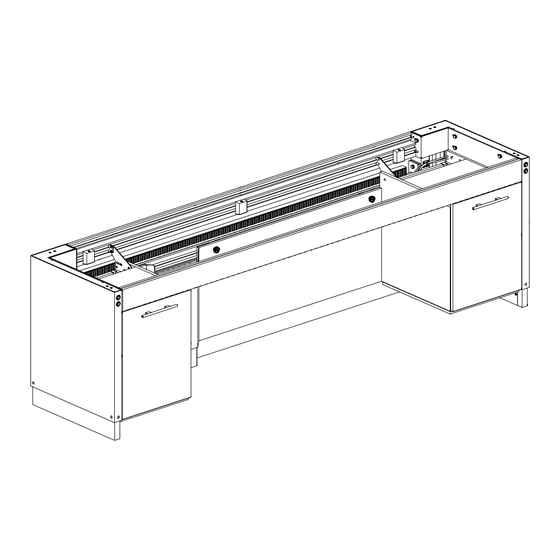
- Page 7 20 mm 10x M8 x 16mm 10x BR M8 Place the motor units upside down on a flat surface on the floor and screw on the frame. Align according to Figure 1.1. Placez les unités motrices à l'envers sur une surface plane au sol et vissez le cadre. Alignez selon la Figure 1.1.
- Page 8 16 mm 4x M8 x 16mm 4x BR M8 Screw on the beam between the motor units. Vissez la poutre entre les unités motrices. SL6400...
- Page 9 10 mm 16 mm 4x - M6 x 10mm Front view of lifting unit. Screw the control panel onto the lower aluminium beam. Move the control pane to the side to a position free from obstacles when raising 300mm. Vue avant de l'unité de levage. Vissez le panneau de commande sur la poutre inférieure en aluminium.
- Page 10 WARNING – Ensure both power supply cords are connected before use AVERTISSEMENT – Avant utilisation, assurez-vous que les deux cordons d'alimentation sont branchés Connect all cables as below Connectez tous les câbles comme ci-dessous Motor left 1 Moteur gauche 1 Motor left 2 Moteur gauche 2 Motor right 1...
- Page 11 SL6400...
- Page 12 Place the unit in the intended location. Please note that the lifting unit must be able to move completely freely and have a gap of at least 5 mm to fixed furnishings. If possible, align the front with other fixed furnishings. There are two mounting holes in each motor unit for securing to the floor.
- Page 13 16 mm 4 x 16 mm If SideLift is ordered without a front piece, a custom front must be mounted with wooden screws through the aluminium profile. Front dimensions = (total length - 94) x 103 x 16 mm. Si SideLift est commandé sans pièce frontale, une façade personnalisée doit être montée avec des vis à bois à travers le profilé...
- Page 14 8x - M5 x 5 mm Mount cover plates on the motor units Montez les plaques de recouvrement sur les unités motrices SL6400...
- Page 15 Connect drain and water in wall or floor Connectez le drain et l'eau dans le mur ou le sol SL6400...
- Page 16 10 mm 16 mm 4x M6 x 10mm 4x BR M6 Mount left and right brackets for lower covers Montez les supports gauche et droit pour les couvercles inférieurs SL6400...
- Page 17 16 mm 16x - 3 x 12 mm Cut and prepare the covers as shown below. Coupez et préparez les couvertures comme indiqué ci-dessous. (mm) C - 150 B - 150 SL6400...
- Page 18 4x M6x25 HEX4 Screw the cover to the brackets. Vissez le couvercle aux supports. SL6400...
- Page 19 Mount the suspended cabinets (accessories) The worktop lift can be equipped with suspended cabinets placed optionally along the entire work top. The cabinets come with active anti-pinch protection along the bottom of the cabinet. Therefore, handle the cabinets extra carefully Montage des armoires suspendues (accessoires) L'élévateur de plan de travail peut être équipé...
- Page 20 6,3x13 Remove the drawers from the cupboards and fit the front hanger brackets loosely so at a later stage they can be adjusted vertically DWG NO. 5x16 REVISION Granberg Interior AB Tel. +46(0)11197750 Fax. +46(0)11127676 info@granberg.se TITLE: Systemskruv 5x16 www.granberg.se...
- Page 21 Fit the rear hanger brackets loosely that they can be adjusted horizontally. Please note that only one hanger bracket is used at the rear when the cabinets are mounted directly against the DWG NO. 5x16 REVISION Granberg Interior AB Tel. +46(0)11197750 Fax. +46(0)11127676 info@granberg.se TITLE: Systemskruv 5x16 www.granberg.se...
- Page 22 Place the cabinets on the floor under the lift. Then lift and hook the front brackets onto the aluminium profile and slide the rear brackets into the rear profile. Placer les armoires au sol sous l'ascenseur. Ensuite, soulevez et accrochez les supports avant sur le profilé en aluminium et faites glisser les supports arrière dans le profil arrière.? SL6400...
- Page 23 M5x10 Screw the lock plates onto all hanger brackets. Vissez les plaques de verrouillage sur tous les supports de suspension avant et arrière. SL6400...
- Page 24 6,3x13 Now lock the height with the remaining system screws. 5x16 Granberg Interior AB DWG NO. REVISION Tel. +46(0)11197750 Lift the cabinet up to max and screw the remaining screws into all front and rear hanger brackets. Fax. +46(0)11127676 info@granberg.se...
- Page 25 The suspended cabinets are fitted with active proximity plates. Connect the cables from the proximity plates to the connection boxes as below. Fix the cables with cable tie mounts as illustrated. Les armoires suspendues sont équipées de plaques de proximité actives. Connectez les câbles des plaques de proximité...
- Page 26 HEX4 Mount brackets for the upper cover panel. Supports de montage pour le panneau de couverture supérieur. SL6400...
- Page 27 16 mm 16x 3 x 12 mm Cut and prepare the covers as shown below. (mm) Coupez et préparez les couvertures comme indiqué ci-dessous. C - 150 B-150 SL6400...
- Page 28 Now mount the upper cover panel Montez maintenant le panneau de couverture supérieur SL6400...
- Page 29 Test operate the lifter up and down a few times and check that everything runs freely without noise. Testez le lève-personne de haut en bas plusieurs fois et vérifiez que tout fonctionne librement et sans bruit. SL6400...
- Page 30 Glue the worktop to the lifting system Coller le plan de travail au système de levage Install the rest of the accesories Installez le reste des accessoires SL6400...
-
Page 31: Functional Tests
Functional tests Complete functional tests should be carried out after installation: Ensure both power supply cords are connected before use! Test run the lift unit up and down all the way to each end position. Make sure that the lift runs freely without obstacles, risk of pinching and noise. - Page 32 Exempel / Exemple Full wheelchair access / Accès complet en fauteuil roulant Cabinets at end pieces / Armoires aux extrémités...
- Page 33 Exempel / Exemple Cabinets under the whole worktop / Armoires sous tout le plan de travail Wheelchair access under sink / Accès fauteuil roulant sous lavabo...
- Page 36 Granberg Interior AB Box 6112 600 06, Norrköping Tel: 011-19 77 50 E-mail: info@granberg.se Internet: www.granberg.se...
Need help?
Do you have a question about the Sidelift 6400 and is the answer not in the manual?
Questions and answers