Table of Contents
Advertisement
Quick Links
Advertisement
Table of Contents

Subscribe to Our Youtube Channel
Related Manuals for Riken Keiki GD-F4A-A


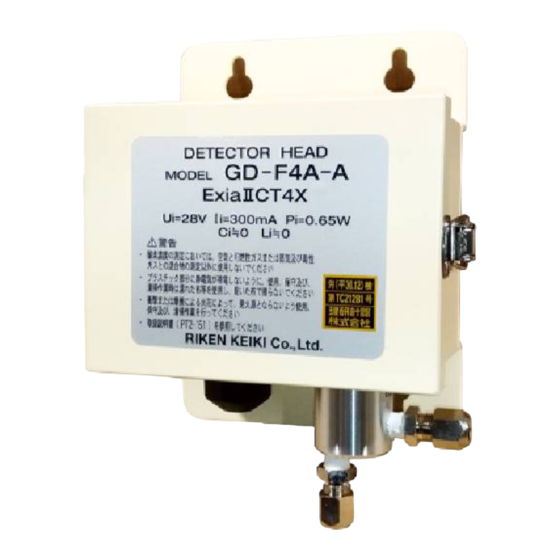
Summary of Contents for Riken Keiki GD-F4A-A
- Page 1 PT2E-2501 Oxygen Gas Detector Head GD-F4A-A Operating Manual (PT2-151)
- Page 2 Operating Precautions This detector is an oxygen deficiency detector that detects oxygen in the air and triggers an oxygen deficiency alarm. The oxygen deficiency detector is a safety unit, not an analyzer or densitometer which performs quantitative/qualitative analysis/measurement for oxygen. Please fully understand the following points before using it, so that it can be used properly.
-
Page 3: Table Of Contents
TABLE OF CONTENTS 1.PRODUCT OUTLINE 1-1. Preface ……………………………………………………………………… 1-2. Application for use …………………………………………………………… 1-3. Definition of DANGER, WARNING, CAUTION and NOTE ………………… 1-4. Method of confirmation for CE/UKCA marking type (Non-explosion proof specification only) ………………… 2.IMPORTANT INSTRUCTIONS FOR THE SAFETY 2-1.... -
Page 4: 1.Product Outline
1.PRODUCT OUTLINE 1-1.Preface Thank you for choosing our fixed type Oxygen Detector Head GD-F4A-A. Please check that the model number of the product you purchased is included in the specifications on this manual. This manual explains how to use the detector and its specifications. It contains information required for using the gas detector properly. -
Page 5: 2.Important Instructions For The Safety
2.IMPORTANT INSTRUCTIONS FOR THE SAFETY 2-1.Danger cases DANGER In case of non-explosion poof system, do not use this unit at the place where combustible gas may exist. 2-2.Warning cases WARNING ・Do not cut the wire for protective ground both inside and outside of instrument. Or, do not disconnect the connection of the ground terminals. -
Page 6: 3.Product Components
3.PRODUCT COMPONENTS 3-1.External dimensions Gas inlet Sensor Cable inlet Cable inlet Gas inlet Sensor Cable inlet Protective Gas outlet ground Protective ground Gas outlet... -
Page 7: 3-2.Names And Functions For Each Part
3-2.Names and functions for each part ⑧ ④ ③ ⑥ ⑦ ① ② ⑨ ⑤ ① Oxygen sensor : Galvanic type sensor to detect oxygen content. ② Sensor retainer : This is a retainer to hold the oxygen sensor (equipped with filter inside). ③... -
Page 8: 3-3.System Composition
3-3.System composition (1) Intrinsically safe system Hazardous area Non-hazardous area Indicator Detector /alarm head unit CVVS-2C 1.25mm or equivalent (max 600m) cable ! WARNING 1.The oxygen detector shall be used as following composition. Non-hazardous Hazardous area area Li Lo Ci Co... - Page 9 (2) Non-explosion proof system Non-hazardous area Non-hazardous area Detector head CVVS-2C 1.25mm or equivalent (MAX 600m) (3) Component inside detector head Drip-proof housing Sensor lead Terminal strip Oxygen sensor Cable gland Gas inlet Shielded cable Gas outlet...
-
Page 10: 4.How To Use
U-bolts as show right figure. (3) Installation to the outdoors For outdoor installation, optional drip-proof cover is required to keep reliable detection although this is a drip-proof design. Contact authorized distributors, dealers or representative appointed by RIKEN KEIKI Co., Ltd. Mounting to the pole... -
Page 11: 4-5.Caution At Wiring Construction
4-5.Caution at wiring construction ! CAUTION ・When make wiring construction, take care not to damage the internal electronics circuit. ・When handle the detector unit, put it at horizontal position. If put it vertically, it tends to fall and damage the detector. ・Power cable and signal cable shall not be laid down together with motive power cable such as motor, etc. -
Page 12: 4-8. Caution At Piping Works
WARNING ・ Ground the zener barrier separately corresponding to the A-class grounding with ground resistance of 10Ω or less. ・ Use the specified cable. ・ For system installation, operation and maintenance, take care not to damage the intrinsically safe design. ・... -
Page 13: 4-9. Example Of Piping Connection
Applicable piping is φ 8(O.D.)-1t copper pipe. Secure the piping connections not to leak. The piping material will be changed depending on corrosive gas contained in a sampled gas. In such case, contact RIKEN KEIKI Co., Ltd. (1) In case of pump suction... -
Page 14: 5.Operation Method
5.OPERATION METHOD 5-1.Preparation for start up Before making power on, take care of the following. If do not keep this, there is the danger of electrical shock and damage of instrument. WARNING ・ Make protective grounding. ・ Check that the wiring with outer unit is made correctly. ・... -
Page 15: 6.Maintenance And Inspection
- Maintenance Contract – Be sure to perform the regular maintenance inspection since this is an instrument for security and safety. If this detector head founds defective, contact our nearest agent or RIKEN KEIKI soon. 6-1.Inspection frequency and items The inspection includes a daily inspection which a person in charge of control and operation of the gas detection instrument performs inspection before work once a day, and a monthly inspection carried out once a month, and periodical inspections conducted by the service personnel designated by manufacturer. -
Page 16: 6-2.How To Calibration
6-2.How to calibration Perform gas calibration at new installation, 6 months maintenance and sensor replacement. 6-2-1.Required kit and tools for calibration Prepare following jigs and tools to perform zero and span adjustments. Calibration gas (standard gas for zero and span) ... -
Page 17: 6-3.Replacing The Sensor 6-3-1.Replacement Frequency Of The Sensor
6-3.Replacing the sensor 6-3-1.Replacement frequency of the sensor To maintain the reliability of the measurement, it is recommendable to replace the sensor periodically. Our oxygen sensor has an enough life span. However, the actual life is depending on the operating conditions. -
Page 18: 6-4.List Of Recommendable Spare Parts For Regular Replacement
6-4.List of recommendable spare parts for regular replacement Name of parts Inspection frequency Replacement interval Q’ty/unit O-ring 1 year 3-6 years (sensor side in the holder) O-ring 1 year 3-6 years (Housing side in the holder) * NOTE ・The replacement interval will change depending on operating condition and it does not mean the warranty period. -
Page 19: 7.Storage, Relocation And Disposal
CAUTION ・ When using a relocated or stopped/stored detector head again, never fail to perform a calibration. For information on readjustment including a calibration, please contact RIKEN KEIKI. 7-3.Disposal of products When the detector head is disposed of, it must be treated properly as an industrial waste in accordance... -
Page 20: 8.Measures At Abnormal Case
8.MEASURES AT ABNORMAL CASE 8-1.Responding to trouble alarm If this detector founds defective, contact our authorized agent or RIKEN KEIKI. 8-2.Before it is thought to be a trouble It may be caused by cable disconnection, short circuit, etc. ・Check the wirings around the related instruments as well as this detector head. -
Page 21: 9.Product Specifications
9.PRODUCT SPECIFICATIONS 9-1.Standard specifications Model GD-F4A-A Detection principle Galvanic cell method Detectable gas Detection method Suction method(with flow passage) Suction flow 1.0±0.3L/min Transmission scheme Direct output from sensor Transmission cable CVVS worth of shield cable(1.25mm )・2-core Transmission distance Less than 600m by CVVS・1.25mm... -
Page 22: 9-4.Detection Principle
9-4.Detection principle [Detection principle] A negative electrode of noble metal and a positive electrode of lead are placed in a resin container filled with electrolyte. A part of the container is opened and covered with a barrier. The negative electrode is installed in contact with the barrier. -
Page 23: 10.Definition Of Terms
10.DEFINITION OF TERMS Galvanic cell Galvanic cell type oxygen sensor that produces a current proportional to the oxygen content permeated through the membrane. Refer to “9-4. Detection principle” for details. Zener barrier Safety retainer for explosion protection by limiting the energy of electric current within a non-ignition level. - Page 24 Manual Log Rev. Amendment Issue data First issue 2017/2/17 Addition: Declaration of Conformity 2022/7/22...
Need help?
Do you have a question about the GD-F4A-A and is the answer not in the manual?
Questions and answers