Table of Contents
Advertisement
Quick Links
Hardware User's Manual
LE12404
Mainframe for up to four LE12406OM units
References:
LE12404 (76-0060)
Version:
V15/06/2015
Panlab, s.l.u
C/Energía, 112
08940 Cornellà de Ll.(Barcelona)
Spain
www.panlab.com
International Calls: +34 934 750 697
Domestic Call: 934 190 709
Fax: +34 934 750 699
Info@panlab.com
Advertisement
Table of Contents

Related Manuals for Harvard Apparatus Panlab LE12404


Summary of Contents for Harvard Apparatus Panlab LE12404
- Page 1 Hardware User’s Manual LE12404 Mainframe for up to four LE12406OM units References: LE12404 (76-0060) Version: V15/06/2015 Panlab, s.l.u International Calls: +34 934 750 697 C/Energía, 112 Domestic Call: 934 190 709 08940 Cornellà de Ll.(Barcelona) Fax: +34 934 750 699 Spain Info@panlab.com www.panlab.com...
- Page 2 Limitation of Liability PANLAB does not accept responsibility, under any circumstances, for any harm or damage caused directly or indirectly by the incorrect interpretation of what is expressed in the pages of this manual. Some symbols may have more than one interpretation by professionals unaccustomed to their usage.
-
Page 3: Symbols Table
1. SYMBOLS TABLE Recognising the symbols used in the manual will help to understand their meaning: DESCRIPTION SYMBOL Warning about operations that must not be done because they can damage the equipment Warning about operations that must be done, otherwise the user can be exposed to a hazard. -
Page 4: Unpacking And Equipment Instalation
3. UNPACKING AND EQUIPMENT INSTALATION WARNING: Failure to follow the instructions in this section may cause equipment faults or injury to the user. A. No special equipment is required for lifting but you should consult your local regulations for safe handling and lifting of the equipment. B. - Page 5 PC Control Some of these instruments are designed to be controlled from a PC. To preserve the integrity of the equipment it is essential that the attached PC itself conforms to basic safety and EMC standards and is set up in accordance with the manufacturers’...
-
Page 6: Maintenance
4. MAINTENANCE WARNING: Failure to follow the instructions in this section may cause equipment fault. PRESS KEYS SOFTLY – Lightly pressing the keys is sufficient to activate them. Equipments do not require being disinfected, but cleaned for removing urine, faeces and odour. - Page 7 2 Open fuse-holder by pulling the flange with regular screwdriver. Figure 2. Open fuse-holder door. 3 Extract fuse holder using the screwdriver. Figure 3. Extract fuse-holder. 4 Replace fuses if necessary. Insert fuses in the fuse-holder in the correct position. CORRECT INCORRECT Figure 4.
-
Page 8: Table Of Contents
5. TABLE OF CONTENTS SYMBOLS TABLE GOOD LABORATORY PRACTICE UNPACKING AND EQUIPMENT INSTALATION MAINTENANCE TABLE OF CONTENTS INTRODUCTION EQUIPMENT DESCRIPTION 7.1. CONTROL UNIT FRONT PANEL 7.2. CONTROL UNIT REAR PANEL EQUIPMENT CONNECTION WORKING WITH THE EQUIPMENT 9.1. TIME BASE 9.2. POWER MODULE 9.3. -
Page 9: Introduction
6. INTRODUCTION The Digital Stimulator LE1404 is an instrument which provides a wide range of stimulation with single/repetitive pulses of selectable constant voltage/current. The LE 12404 has not time base it has BNC connectors to interface with an external time base device. -
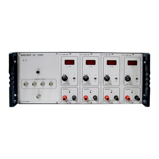
Page 10: Equipment Description
7. EQUIPMENT DESCRIPTION 7.1. CONTROL UNIT FRONT PANEL Figure 7. LE 12404 Front panel. LE 12404 has not time base, it has 4 power modules and a panel with 4 BNC connectors to activate each power module, and a fifth BNC connector to activate the 4 power modules at the same time. - Page 11 ON: 3mm red coloured led that is on when you turn on the stimulator. DC: You will obtain continuous output in the power modules while you press this button. INDEPENDENT CHANNELS: There are 4 BNC connectors; one for each power module, the purpose of these BNC connectors is connect the stimulator to an external TTL timing generator that will replace the time base module.
- Page 12 ON: Two-colour led. When the output is active, it is green and blinks to the frequency of pulses. An overload is indicated when the led is red. The system enters overload state when there is a short-circuit in the output or output power is higher than module power for 3 minutes.
-
Page 13: Control Unit Rear Panel
7.2. CONTROL UNIT REAR PANEL POWER Figure 10. LE 12404 Rear Panel. POWER: Main switch, power inlet and fuse holder. Mainframe for up to four LE 12406OM units... -
Page 14: Equipment Connection
8. EQUIPMENT CONNECTION Figure 11. LE 12404 connection. Just connect the electrodes to both positive and negative outputs of each Power Module. You will need an external TTL time generator to activate the 4 power modules simultaneously with the common BNC connector, or 4 independent TTL time generators to activate each power module independently. -
Page 15: Working With The Equipment
9. WORKING WITH THE EQUIPMENT 9.1. TIME BASE The LE 12404 has not time base as the other models of stimulators, it has a panel with 5 BNC connectors. Four of them control each one a Power Module and the fifth one controls the 4 power modules at the same time. -
Page 16: Troubleshooting
10. TROUBLESHOOTING This table features instructions to solve the most frequent problems. PROBLEM SOLUTION Ensure that the voltage of mains is the same as that selected in the fuse The equipment does not start up. holder. Check the condition of the fuses. ... -
Page 17: Preventive Maintenance
11. PREVENTIVE MAINTENANCE EXPERIMENT ELECTRODES CLEANING ELECTRODES CONNECTION CHECKING Mainframe for up to four LE 12406OM units... -
Page 18: Technical Specifications
12. TECHNICAL SPECIFICATIONS POWER SUPPLY Input voltage: 115/ 230V~ Frequency: 50 /60 Hz Fuse: 2 fuses 5x20mm 2 A 250V Fast Maximum Power: 110W Conducted Noise: EN55022 /CISPR22/CISPR16 class B ENVIRONMENTAL CONDITIONS Operating temperature: 10°C to +40°C Operating Relative Humidity: 0% to 85% RH, non-condensing Storage temperature: 0°C to +50°C, non-condensing... - Page 19 DECLARACIÓN DE CONFORMIDAD DECLARATION OF CONFORMITY DECLARATION DE CONFORMITÉ Nombre del fabricante: Panlab s.l.u. Manufacturer’s name: www.panlab.com Nom du fabricant: info@panlab.com Dirección del fabricante: Energía, 112 Manufacturer’s address: 08940 Cornellà de Llobregat Adresse du fabricant: Barcelona SPAIN Declara bajo su responsabilidad que el producto: DIGITAL STIMULATOR Declares under his responsibility that the product: Déclare sous sa responsabilité...
- Page 20 Mainframe for up to four LE 12406OM units...
Need help?
Do you have a question about the Panlab LE12404 and is the answer not in the manual?
Questions and answers