
Subscribe to Our Youtube Channel
Related Manuals for BRUEL & KJAER NEXUS 2690


Summary of Contents for BRUEL & KJAER NEXUS 2690
- Page 1 Technical Documentation ™ The NEXUS Range of Conditioning Amplifiers Types 2690, 2691, 2692 and 2693 Service Manual BI 5042−12...
- Page 3 The NEXUS™ Range of Conditioning Amplifiers Types 2690, 2691, 2692 and 2693 Service Manual Valid from serial number 02340582 Revision September 2004 Brüel & Kjær The NEXUS Range of Conditioning Amplifiers BI 5042−12 Service Manual...
- Page 4 Safety Considerations This apparatus has been designed and tested in accordance with IEC Publication 1010, Safety Requirements for Electronic Equipment for Measurement, Control and Laboratory Use (see specifications), and has been supplied in safe condition. This Manual contains information and warnings which must be followed by the user to ensure safe operation and to retain the apparatus in safe condition.
-
Page 5: Table Of Contents
Contents 1. General Information ....................... 1 Edition Number ........................ 2 Safety ..........................2 Instrument Versions ......................2 Service Policy........................3 Exchange Scheme ......................3 Field Replaceable Parts....................4 Repair of PCBs......................5 Repair of Mechanical Parts ..................5 Repair Procedure ......................5 Calibration and Testing.................... - Page 6 Contents Optional Filters ......................26 Inherent Noise* ......................27 Checking Test Signals ....................27 Overload ........................29 Checking DeltaTron Channels ZX 2693 ................. 31 Checking Calibrated Output ..................31 Checking Low-pass Filters* ..................32 Checking High-pass Filters ..................33 Optional Filters ......................34 Inherent Noise* ......................
-
Page 7: General Information
Chapter 1 General Information BI 5042 -12 The NEXUS Range of Conditioning Amplifiers Service Manual... -
Page 8: Edition Number
Chapter 1 — General Information Edition Number Edition Number If any major changes are made to the instrument and/or Service Manual, a new edi- tion of the Service Manual will be released. Any new edition can be recognised by the Literature Number (BI 5042-xx) given at the bottom of odd numbered pages, where xx is the edition number. -
Page 9: Service Policy
Chapter 1 — General Information Service Policy The revision number is changed for small updates of the program, e.g., error correc- tions, minor new functions and special customer versions. The history number is generally for internal releases, however, it is also used to indicate minor changes to the program. -
Page 10: Field Replaceable Parts
Chapter 1 — General Information Service Policy 1.4.2 Field Replaceable Parts Note: FRPs can only be obtained for NEXUS version 2.2 and later. Description Optional Filter Type FRP Forward No. FRP Return No. Processor Channel – ZD 0816–FRF ZD 0816–FRR Module (ZD 0816) No optional filter ZX 2690–FRF... -
Page 11: Repair Of Pcbs
Chapter 1 — General Information Service Policy 1.4.3 Repair of PCBs Analogue Channel Boards NEXUS is highly modular and all printed circuit boards are based on a multi-layer/ surface mounted technique which make repair mainly a question of identifying the faulty module/PCB/channel and replace it with a “new”... -
Page 12: Calibration And Testing
Chapter 1 — General Information Calibration and Testing 1. Send the complete instrument to Brüel & Kjær headquarters in Nærum. A repair time of up to 10 days + transport time must be allowed. 2. Locate the faulty part and replace it with an FRP and test the functionality of the instrument. -
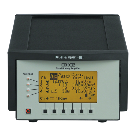
Page 13: Front Panel
Chapter 1 — General Information Front Panel AO 0087 BNC to BNC cable AO 0127 BNC to Brüel & Kjær cable Front Panel Fig.1.1 Front panel of NEXUS Conditioning Amplifier On/Off key. When switched off, nearly all circuits in the instrument, including the interface and the charging circuit, are switched off. -
Page 14: Back Panel
Chapter 1 — General Information Back Panel Back Panel Fig.1.2 Back panel of NEXUS Conditioning Amplifier RS–232 Host Serial interface socket for remote control and output of measure- ment results (see Vol. 2). The RS–232 Host connector is a 9-pin D- range female connector which is used for connection to a PC, a remote control unit or the previous NEXUS unit in a “daisy-chain”... - Page 15 Chapter 1 — General Information Back Panel DC 10 – 33 V Coaxial DC-socket for connection to an external 10 to 33 V DC source. Complies with ISO DP 7637/1, 12 V and DP 7637/2, 24 V. The conditioning amplifier can be set to charge the battery from an external 14 to 33 V DC source.
-
Page 16: Emc Immunity
Chapter 1 — General Information EMC Immunity Output Ch. 1 to 4 Up to four BNC output sockets. You can select grounded or floating mode. The output is protected against short-circuiting and voltage overload, even when the instrument is switched off. Warning: If floating output is selected, care must be taken to limit the signal ground current in order to prevent electrical haz- ards. -
Page 17: Service Note
Chapter 2 Service Note BI 5042 -12 The NEXUS Range of Conditioning Amplifiers Service Manual... -
Page 18: General
Chapter 2 — Service Note General General From time to time some minor changes may be made to improve the performance and serviceability of NEXUS amplifiers. All information concerning these changes, or any other changes to the Service manual, will be released in the form of a Service Note. -
Page 19: Checking Procedure
Chapter 3 Checking Procedure BI 5042 -12 The NEXUS Range of Conditioning Amplifiers Service Manual... -
Page 20: Introduction
Chapter 3 — Checking Procedure Introduction Introduction The Checking procedure is divided up into 2 different modes. A built-in Self-test program that checks the digital parts of NEXUS. A Manual Checking Procedure that checks most of the analogue circuit based on the factory checks of NEXUS. -
Page 21: Checking Charge Channels Zx 2692
Chapter 3 — Checking Procedure Checking Charge Channels ZX 2692 Before the checking procedure, the generator and voltmeter must be calibrated to- gether. Set the generator to 1 V output at 1 kHz and adjust the voltmeter reading to 1 V ±0.1 dB. The checks in the Manual Checking Procedure can be performed separately or in sequence. - Page 22 – Generator frequency: 1 kHz Checking Output Levels* Check the output levels for each of the 13 gain settings shown in Table 3.1. The measured values must correspond to the NEXUS output levels specified in the table within the tolerances specified in the minimum and maximum acceptance levels. If any of the measured values exceed the specified tolerances, the associated charge channel is defect and must be replaced with a new channel within the FRP arrange- ment.
-
Page 23: Checking Low-Pass Filters
Chapter 3 — Checking Procedure Checking Charge Channels ZX 2692 3.4.2 Checking Low-pass Filters* Measurement Setup 1. Use the same setup as previously 2. Set up the following parameters on the NEXUS unit: –2 – Output Sensitivity: 1.000 V/ms , (Amplifier Setup menu) –... -
Page 24: Checking High-Pass Filters
Chapter 3 — Checking Procedure Checking Charge Channels ZX 2692 Generator Low-pass Generator Maximum Deviation Nominal Level Meas. No. Filter Frequency from Nominal Output Output (dBV) (dBµv (kHz) (Hz) (dBV) 20.0 120.0 ±0.3000 100.0 120.0 –1.0 ±0.6000 200.0 120.0 ±0.3000 1000.0 120.0 –1.0... -
Page 25: Optional Filters
Chapter 3 — Checking Procedure Checking Charge Channels ZX 2692 Checking Output Levels The procedure is to measure the output levels at the –1 dB frequencies and the levels at 5 f = the filter cut-off frequency) for the different high-pass filters. Check the output levels for each of the 7 combinations of high-pass filters and input frequencies as shown in Table 3.3. -
Page 26: Checking Test Signals
Chapter 3 — Checking Procedure Checking Charge Channels ZX 2692 3. Set up the following parameters on the NEXUS unit: –2 – Output Sensitivity: 1000 V/ms (Amplifier Setup menu) –2 – Transducer Sensitivity: 1 nC/ms – Low-pass Filter: 30 kHz (Amplifier Setup menu) –... -
Page 27: Overload
Chapter 3 — Checking Procedure Checking Charge Channels ZX 2692 Transmitter: – Connect a storage scope to the output. Check that the signal is a square wave: minimum +13 V to –13 V, period time 33.3 µs Checking Other Channels Perform the same checks for all remaining charge input channels 3.4.7 Overload... -
Page 28: Checking Microphone Channels Zx 2690 And Sound Intensity Channels Zx 2691
Chapter 3 — Checking Procedure Checking Microphone Channels ZX 2690 and Sound Intensity Channels ZX 2691 Generator Level: 9.2 V ⇒ No overload – Generator Level: 10.0 V ⇒ Signal overload (on common circuit) – Common Mode Overload Short the input through WB 1026 Set Input to Floating: Yes (Floating/Correction menu) Connect the generator signal (1 kHz) between the chassis and the floating input ground node... - Page 29 Chapter 3 — Checking Procedure Checking Microphone Channels ZX 2690 and Sound Intensity Channels ZX 2691 3. Set up the 2636 to 1 V range. 4. Set up the following parameters on the NEXUS unit: – Output Sensitivity: – 20 to +80 dB (according to Table 3.5), (Amplifier Setup menu) –...
-
Page 30: Checking Low-Pass Filters
Chapter 3 — Checking Procedure Checking Microphone Channels ZX 2690 and Sound Intensity Channels ZX 2691 Output Generator Maximum Deviation Meas. Nexus Sensitivity Frequency Generator Level from Nominal Output Output Level –2 (Hz) (dBV) (V/ms 1000.0 –80 dBV (0.0001 V) –10 dBV (0.316 V) ±1... -
Page 31: Checking High-Pass And A-Weighting Filters
Chapter 3 — Checking Procedure Checking Microphone Channels ZX 2690 and Sound Intensity Channels ZX 2691 Low-pass Generator Generator Nominal Maximum Deviation Meas. No. Filter Frequency Level Output Level from Nominal Output (kHz) (Hz) (dBV) (dBV) 20.0 ±0.3000 100.0 –1.0 ±0.6000 200.0 ±0.3000... -
Page 32: Optional Filters
Chapter 3 — Checking Procedure Checking Microphone Channels ZX 2690 and Sound Intensity Channels ZX 2691 Checking Output Levels The procedure is to measure the output levels at the –1 dB frequencies and the levels at 5 f = the filter cut-off frequency) for the different high-pass filters. Check the output levels for each of the 13 combinations of high-pass filters and input frequencies as shown in Table 3.7. -
Page 33: Inherent Noise
Chapter 3 — Checking Procedure Checking Microphone Channels ZX 2690 and Sound Intensity Channels ZX 2691 3.5.5 Inherent Noise* A Measuring Amplifier Type 2636 is used for measuring inherent noise. Measurement Setup The selected input must be short circuited at the input socket. 1. - Page 34 Chapter 3 — Checking Procedure Checking Microphone Channels ZX 2690 and Sound Intensity Channels ZX 2691 ⋅ 200V R , where R is the input impedance of the voltmeter ------------------------------ - 210kΩ Voltmeter ≥ 9 MΩ Checking the Supply Voltage The supply voltage is not accessible with cable WL 273.
-
Page 35: Overload
Chapter 3 — Checking Procedure Checking Microphone Channels ZX 2690 and Sound Intensity Channels ZX 2691 – Connect the 2636 to the BNC output for CIC on cable WL 1273 – Check that the voltage is approx. 7 V ±1 V –... - Page 36 Chapter 3 — Checking Procedure Checking Microphone Channels ZX 2690 and Sound Intensity Channels ZX 2691 Common Mode Overloads Short the Input (Pin 2 and 4 in LEMO connector) on the NEXUS unit Connect the generator signal between the chassis and Pin 2 and 4 Set up the following on the Generator: –...
-
Page 37: Checking Deltatron Channels Zx 2693
Chapter 3 — Checking Procedure Checking DeltaTron Channels ZX 2693 Checking DeltaTron Channels ZX 2693 3.6.1 Checking Calibrated Output Measurement Setup 1. Connect the Sine/Noise Generator Type 1049/1051 to the desired DeltaTron input channel. Use a BNC to BNC cable. 2. -
Page 38: Checking Low-Pass Filters
Chapter 3 — Checking Procedure Checking DeltaTron Channels ZX 2693 Output Generator Maximum Deviation Meas. NEXUS Sensitivity Frequency Generator Level from Nominal Output Output Level –2 (Hz) (dBV) (V/ms 0.100 1000.0 0 dBV (1 V) –20 dBV (0.1 V) ±0.5000 0.316 1000.0 0 dBV... -
Page 39: Checking High-Pass Filters
Chapter 3 — Checking Procedure Checking DeltaTron Channels ZX 2693 Checking Output Levels The procedure is to measure the output levels at the –1 dB frequencies and the levels at = the filter cut-off frequency) for the different low-pass filters. Check the output levels for each of the 14 combinations of low-pass filters and input frequencies as shown in Table 3.11. -
Page 40: Optional Filters
Chapter 3 — Checking Procedure Checking DeltaTron Channels ZX 2693 2. Set up the following parameters on the NEXUS unit: – Output Sensitivity: 0 dB, (Amplifier Setup menu) – Low-pass Filter: 30 kHz (Amplifier Setup menu) – High-pass Filter: According to Table 3.12 –... -
Page 41: Inherent Noise
Chapter 3 — Checking Procedure Checking DeltaTron Channels ZX 2693 3.6.5 Inherent Noise* A Measuring Amplifier Type 2636 is used for measuring inherent noise. Measurement Setup 1. The selected input must be short circuited. 2. Connect the output for the selected channel to Measuring Amplifier Type 2636 with a BNC to Brüel &... -
Page 42: Checking Test Signals
Chapter 3 — Checking Procedure Checking DeltaTron Channels ZX 2693 3.6.7 Checking Test Signals Checking the Tacho Probe Supply Use the DMM to measure the voltage between the inner and outer shield on the BNT socket for the associated DeltaTron channel. The voltage should be approx. +8 V DC at the inner shield (nominal voltage at 100 Ω... - Page 43 Chapter 3 — Checking Procedure Checking DeltaTron Channels ZX 2693 Connect the generator signal between the chassis and the floating input/input ground terminal on NEXUS Set up the following on the Generator: – Generator Frequency: 1 kHz Generator Level: 3.0 V ⇒ No overload –...
-
Page 44: Checking Optional Single And Double Integration Filters Ze 0788
Chapter 3 — Checking Procedure Checking Optional Single and Double Integration Filters ZE 0788 – Input Floating: No (Floating/Correction menu) Terminate Input with 10 KΩ ⇒ Τransducer Voltage Overload – Terminate Input with 0 Ω ⇒ Τransducer Voltage Overload – Terminate Input with 1.5 KΩ... -
Page 45: Checking Optional A-, B-, C- And D-Weighting Filters Ze 0794
Chapter 3 — Checking Procedure Checking Optional A-, B-, C- and D-Weighting Filters ZE 0794 If any of the measured values exceed the specified tolerances, the associated input module is defect and must be replaced with a new channel module within the FRP arrangement. - Page 46 Chapter 3 — Checking Procedure Checking Optional A-, B-, C- and D-Weighting Filters ZE 0794 – A-, B-, C- or D-weighting according to Table 3.15 – Output Floating: No (Floating/Correction Setup menu) 5. Set up the generator output to 1 V, according to Table 3.15 Checking Output Levels Check the output levels for each of the combinations of filters and frequencies as shown in Table 3.15.
-
Page 47: Theory Of Operation
Chapter 4 Theory of Operation BI 5042 -12 The NEXUS Range of Conditioning Amplifiers Service Manual... -
Page 48: Introduction
Chapter 4 — Theory of Operation Introduction Introduction To make troubleshooting easier, some knowledge of the principle of operation may be helpful. This section contains a description to block level of the principle of oper- ation for NEXUS. Functional Description 4.2.1 Input Channel Modules Each input channel is split op into three modules: An input module (that can be... - Page 49 Chapter 4 — Theory of Operation Block Diagrams 0 dB, +20 dB -10 dB +20, +40 dB Input 4.7V 10.5V Common Input Mode Overload Signal Input Overload 020079 Fig.4.2 Charge input module for Type 2692 A. Fitted with TNC con- nector Input Socket (External view) Signal...
- Page 50 Chapter 4 — Theory of Operation Block Diagrams 100 Hz -10, Fine gain +10 Hz, 100kHz 0.001 dB steps +10 dB (0 - 12 dB) HP-filter LP-filter 10.5V Internal Signal Overload 020077 Fig.4.5 Common module. This module is used for all input chan- nels.
-
Page 51: Electrical Diagrams
Chapter 5 Electrical Diagrams BI 5042 -12 The NEXUS Range of Conditioning Amplifiers Service Manual... -
Page 52: Frp Policy
Chapter 5 — Electrical Diagrams FRP Policy FRP Policy There are no electrical diagrams in this Service Manual since most of the modules and printed circuits in NEXUS are covered by the FRP policy. The NEXUS Range of Conditioning Amplifiers Brüel &... -
Page 53: Mechanical Assembly
Chapter 6 Mechanical Assembly BI 5042 -12 The NEXUS Range of Conditioning Amplifiers Service Manual... -
Page 54: Dismantling The Display Unit
Chapter 6 — Mechanical Assembly Dismantling the Display Unit Dismantling the Display Unit YG 0485 Battery Lid DP 0921 YG 0485 Rear Panel DP 0918 YG 0485 Rubber Gasket DS 0932 YG 0485 Housing DC 0587 (including 4 rubber feet DF 0241) Rubber Gasket DS 0932... -
Page 55: Dismantling The Motherboard (Ze 0785)
Chapter 6 — Mechanical Assembly Dismantling the Motherboard (ZE 0785) To remove a ribbon cable, use your fingernails to move the ends of the support bar approx. 1 mm backward simultaneously. The ribbon cable can then be discon- nected (direction A as illustrated in Fig.6.2). To reassemble, put the ribbon cables fully into the connectors. -
Page 56: Dismantling A Channel
Chapter 6 — Mechanical Assembly Dismantling a Channel 020081 Fig.6.4 Removing the circuit board assembly from the casing Dismantling a Channel Remove the mother board as described in section 6.2. 1. Use a 14 mm wrench to loosen the nuts that secure the input and output sockets for the channel in question, see Fig.6.5. -
Page 57: Dismantling The Main Processor Board
Chapter 6 — Mechanical Assembly Dismantling the Main Processor Board Warning: Be careful not to damage the surface mount components on the rear circuit board. 2. After removing the nuts you can pull out the complete channel. Dismantling the Main Processor Board Remove the front connector board as described in section 6.2. - Page 58 The NEXUS Range of Conditioning Amplifiers Brüel & Kjær Service Manual...
-
Page 59: Servicing The Nexus Using Atac
Chapter 7 Servicing the NEXUS using ATAC BI 5042 -12 The NEXUS Range of Conditioning Amplifiers Service Manual... -
Page 60: Introduction
Chapter 7 — Servicing the NEXUS using ATAC Introduction Introduction This section is intended to serve as a User Guide for the Service 269X Software, which is an integral part of the Calibration Software for ATAC, and is used for servic- ing the NEXUS. -
Page 61: Service 269X Menu
Chapter 7 — Servicing the NEXUS using ATAC Service 269X Menu Service 269X Menu Select Service 269X from the Main menu, the system reads the configuration from the NEXUS and displays a menu corresponding to it. In the following example the configuration of the NEXUS consists of 1 Preamp, 1 Charge and 2 CCLD channels: The following tests/adjustments can be done from this menu: Preamp... -
Page 62: Connecting The Nexus
Chapter 7 — Servicing the NEXUS using ATAC Service 269X Menu CCLD Adjust freq. resp. This option is used to adjust the frequency response, the instrument must be open prior to the selection, as the adjustment is done manually on potentiome- ters (one on each channel). -
Page 63: Correction Factors
Chapter 7 — Servicing the NEXUS using ATAC Service 269X Menu 7.3.2 Correction Factors This option allows you to measure all channels and AUX-modules, calculates neces- sary corrections and downloads them. The module measures the deviation from the actual Gain to the expected Gain, and calculates the correction factor needed. -
Page 64: Adjust Polarization Voltage
Chapter 7 — Servicing the NEXUS using ATAC Service 269X Menu 7.3.3 Adjust Polarization Voltage This option allows you to measure the Polarization Voltage and downloads correc- tions. The test of the Polarisation Voltage is done by resetting the correction to its default value 7, measuring the deviation, calculating and downloading the correct value, and measuring the Polarisation Voltage in order to verify that this new setting is correct. -
Page 65: Adjust Frequency Response
Chapter 7 — Servicing the NEXUS using ATAC Service 269X Menu 7.3.4 Adjust Frequency Response This option is used to adjust the frequency response, the instrument must be open prior to the selection, as the adjustment is done manually on potentiometers (one on each channel). -
Page 66: Set Configuration
Chapter 7 — Servicing the NEXUS using ATAC Set Configuration Set Configuration If your NEXUS needs configuring, either because you have changed it, or for some reason it has lost its configuration, press F9 to enter the Set Configuration Window. This gives you the possibility of setting the Channel type to one of the following: 1.
Need help?
Do you have a question about the NEXUS 2690 and is the answer not in the manual?
Questions and answers