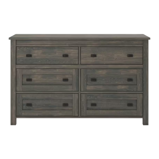
Summary of Contents for Ameriwood HOME Farmington 5685213COM
- Page 4 BOTTOM FIXED SHELF T5685213010GO T5685213020GO T5685213030GO QTY: 1 PC QTY: 1 PC QTY: 1 PC CENTER MOLDING LOWER SUPPORT UPPER FRONT MOLDING T5685213040GO T5685213060GO T5685213050GO QTY: 1 PC QTY: 2 PCS QTY: 1 PC UPPER SIDE MOLDING LEFT PANEL RIGHT PANEL T5685213090GO T5685213070GO T5685213080GO...
- Page 5 LEFT PANEL RAIL LOWER RAIL RIGHT PANEL RAIL T5685213110GO T5685213100GO T5685213120GO QTY: 2 PCS QTY: 1 PC QTY: 1 PC RIGHT BACK LEG LEFT FRONT LEG RIGHT FRONT LEG LEFT BACK LEG T5685213160GO T5685213130GO T5685213140GO T5685213150GO QTY: 1PC QTY: 1PC QTY: 1PC QTY: 1PC UPPER DRAWER FRONT...
- Page 6 UPPER DRAWER BACK UPPER DRAWER SIDE RIGHT LOWER DRAWER FRONT T5685213220GO T5685213210GO T5685213230GO QTY: 2 PCS QTY: 2 PCS QTY: 4PC DRAWER SUPPORT LOWER DRAWER SIDE LEFT LOWER DRAWER BACK T5685213270GO T5685213240GO T5685213260GO QTY: 6PCS QTY: 4 PC QTY: 4PCS DRAWER BOTTOM T5685213280GO QTY: 6PCS...
- Page 8 5685213 M4 x 19mm Ø8 x 20mm Ø8 x 30mm Ø15 x 10mm ×26 ×74 ×74 ×8 CAM LOCK CAM BOLT WOOD DOWEL BOLT TGO2100 TGO2000 TGO2900 TGO1608 M4 x 9 mm Ø4.2 x 45mm Ø4 x 20mm Ø3 x 12mm ×16 ×40 ×14...
- Page 9 ×16 1.1 Cam bolt (2) into (M), (N), (O) and (P) as illustrated.
- Page 10 ×8 2.1 Insert (3) into (G) and (H) as illustrated.
- Page 11 ×12 Proper orientation of CAM LOCK 3.1 Attach (M), (O) into (G) with (1) as illustrated. 3.2 Attach (P), (N) into (H) with (1) as illustrated. Small holes in rear surface...
- Page 12 ×3 ×3 ×1 ×12 15-2 4.1 Attach (15-2) into (G), (M) with (9) as illustrated. 4.2 Insert (3) into (G) as illustrated. 4.3 Cam bolt (2) into (G) as illustrated. 15-2 15-2 15-2 15-2...
- Page 13 ×3 ×3 ×1 ×12 16-2 5.1 Attach (16-2) into (H), (N) with (9) as illustrated. 5.2 Insert (3) into (H) as illustrated. 5.3 Cam bolt (2) into (H) as illustrated. 16-2 16-2 16-2 16-2...
-
Page 14: Finished Edge
×7 6.1 Attach (I), (J) into (G) with (7) as illustrated. 6.2 Attach (K) into (G) with (7) as illustrated. FINISHED EDGE... - Page 15 ×7 7.1 Attach (I), (J) into (H) with (7) as illustrated. 7.2 Attach (L) into (H) with (7) as illustrated. FINISHED EDGE...
- Page 16 ×1 ×1 ×1 ×8 16-2 15-2 8.1 Insert (3) into (AC) as illustrated. 8.2 Attach (15-2),(16-2) into (AC) with (9) as illustrated. FINISHED EDGE 15-2 15-2 FINISHED EDGE 15-2 16-2...
- Page 17 ×1 ×2 ×2 ×16 16-2 15-2 9.1 Insert (3) into (AD) as illustrated. 9.2 Attach (15-2), (16-2) into (AD) with (9) as illustrated. FINISHED EDGE 16-2 15-2 FINISHED EDGE 15-2 16-2 15-2 16-2...
- Page 18 ×2 10.1 Cam bolt (2) into (AD) as illustrated. FINISHED EDGE FINISHED EDGE...
- Page 19 ×14 ×14 ×1 11.1 Cam bolt (2) into (A), (D), (C) as illustrated. 11.2 Attach (13) into (A) with (10) as illustrated. 11.3 Insert (3) into (B), (E), (F) and (C) as illustrated. FINISHED EDGE FINISHED EDGE E x 2...
-
Page 20: End View
Proper orientation of CAM LOCK ×6 12.1 Attach (F) into (A) with (1) as illustrated. 12.2 Attach (D) into (C) with (1) as illustrated. FINISHED EDGE Small holes in rear surface END VIEW... - Page 21 ×2 Proper orientation of CAM LOCK ×2 13.1 Attach (AC) into (C) with (6) as illustrated. 13.2 Attach (AD) into (C) with (1) as illustrated. FINISHED EDGE FINISHED EDGE...
- Page 22 Proper orientation of CAM LOCK ×2 14.1 Attach (E) into (AD) with (1) as illustrated. FINISHED EDGE FINISHED EDGE...
- Page 23 ×2 15.1 Attach (R) into (B) as illustrated. 15.2 Attach (B) into (AD) with (6) as illustrated. FINISHED EDGE FINISHED EDGE...
- Page 24 ×10 16.1 Attach (M), (G), (O) and (H), (N), (P) into (C), (E), (B) with (1) as illustrated. FINISHED EDGE...
- Page 25 ×6 17.1 Attach (A) into (G), (H), (AC) with (1) as illustrated.
- Page 26 ×26 18.1 Attach (Q) into (P), (O), (A) and (B) with (1) as illustrated.
- Page 27 ×12 ×12 Proper orientation of CAM LOCK ×12 19.1 Cam bolt (2) into (S) as illustrated. 19.2 Attach (U), (T) and (AA) into (S) with (1) as illustrated. 19.3 Attach (AB) and (V) into (U), (T) and (AA) with (6) as illustrated.
- Page 28 ×12 ×2 ×2 ×8 15-1 16-1 ×4 20.1 Attach (15-1) into (S1) with (9) as illustrated. 20.2 Attach (16-1) into (S2) with (9) as illustrated. 20.3 Attach (14) into (S) with (4) as illustrated. 15-1 16-1 15-1 16-1...
- Page 29 ×24 ×24 Proper orientation of CAM LOCK ×24 21.1 Cam bolt (2) into (W) as illustrated. 21.2 Attach (X), (Y) and (AA) into (W) with (1) as illustrated. 21.3 Attach (AB) and (Z) into (X), (Y) and (AA) with (6) as illustrated.
- Page 30 ×24 ×4 ×4 ×16 15-1 16-1 ×8 22.1 Attach (15-1) into (X) with (9) as illustrated. 22.2 Attach (16-1) into (Y) with (9) as illustrated. 22.3 Attach (14) into (W) with (5) as illustrated. 15-1 16-1 15-1 16-1...
- Page 31 ×1 ×1 THIS UNIT MUST BE SECURE TO THE WALL TO HELP PREVENT TIPOVER. FOLLOW THESE INSTRUCTIONS TO INSTALL THE ANTI-TIPPING SAFETY BRACKET PROVIDED WITH THIS PRODUCT Hole Consult your local hardware store for appropriate Option 1 STUD anchors to securely attach the safety bracket Option 2 WALLBOARD Install tipover restraint provided...
- Page 32 24.1 Push the Drawer (S) and (W) into the nightstand as illustrated Cabinet Slide Please note, you will have 2 upper drawer and 4 lower drawers. These drawers assemble in the same manner. The only difference is the upper drawer (smaller in height) will use a different size drawer bracket.
- Page 33 75 lbs 34.0 kg. 35 lbs 15.9 kg.


