Table of Contents
Advertisement
Quick Links
Laboratory Fluorescent
Biological Microscope
Model Number
BS-7000A
User Manual
This manual is written for laboratory biological microscope BS-7000A. For safety, exerting best
performance of the instrument, and making you familiar with the instrument entirely, we strongly
recommended that you carefully read this manual before using the microscope.
Advertisement
Table of Contents
Troubleshooting

Related Manuals for BestScope BS-7000A


Summary of Contents for BestScope BS-7000A
- Page 1 BS-7000A User Manual This manual is written for laboratory biological microscope BS-7000A. For safety, exerting best performance of the instrument, and making you familiar with the instrument entirely, we strongly recommended that you carefully read this manual before using the microscope.
-
Page 2: Table Of Contents
BestScope International Limited Content User Notices..........................1 1. Safety note........................1 2. Maintenance........................1 Optical Microscope Part......................1 1. Name of Components...................... 1 2. Installation........................1 3. Adjustment........................1 4. Operation..........................1 5. Technical Specifications....................1 6.Trouble shooting......................1 FL-800 Epi-fluorescent Attachment Part..................1 User Notices.........................1... -
Page 3: User Notices
BestScope International Limited User Notices 1. Safety note 1. Carefully open the box, avoid the accessories, like lens, dropping to ground and being damaged. 2. Do keep the instrument out of direct sunlight, high temperature or humidity, dusty and easy shaking environment. - Page 4 BestScope International Limited moisture. Do not disassemble any parts of the microscope. That will affect the function or decline the performance of the microscope. Place the instrument in a cool, dry position. After using the microscope, remember to cover it...
-
Page 5: Optical Microscope Part
BestScope International Limited Optical Microscope Part 1. Name of Components Video Port (optional) Eyepiece (Ocular) Trinoclular Viewing Unit Nosepiece Objective Lamp House Mechanical Stage... -
Page 6: Installation
BestScope International Limited 2. Installation 2-1 Installation Diagram The following figure shows the installation sequence of the components. The number in the figure show the installation steps. Before installing, be sure every components is clean, do not score any parts or glass surface. - Page 7 BestScope International Limited Video Port (optional) ⑥ ⑤ 10×Wide Field Eyepiece Trinocular Viewing Unit ② ④ Infinite Plan Objective ① ③ Microscope Body Mechanical Stage Support Device Lamp House...
- Page 8 BestScope International Limited 2-2 Installation Steps Guide Board Figure 1 Locking Block and Bolt Figure 2 Figure 3...
- Page 9 BestScope International Limited 2-2-1 Installing the Mechanical Stage Support Device Before installing the device, be sure to adjust the coarse focus knob. Make the guide board (see figure 1)down to the lowest position, so you can install the mechanical stage support device easily.
- Page 10 BestScope International Limited 2-2-2 Installing the Trinocular Viewing Unit Insert the trinocular viewing unit (figure4) into the microscope head (figure5), turn to a proper position, then use the hexagon wrench screw down the bolt to fix ( See figure 5 ).
- Page 11 BestScope International Limited 2-2-4 Installing the Lamp House Keep the bolt on the lamp house (figure 6) in line with the jack on the back of the microscope (like the show of figure 7), then pushing the lamp holder into the illumination kits gently until they are against each other (figure 8).
- Page 12 BestScope International Limited 2-2-6 Installing the Eyepiece Eyepiece Insert the eyepiece (figure 11) into the eyepiece tube until they are against each other. The result is showing in the figure 14. 2-2-7Installing the Video Port (optional) Insert the video port (figure 12) into the...
-
Page 13: Adjustment
BestScope International Limited 3. Adjustment Video Port (optional) Diopter Ring Clocking Set Left Fine Focus Knob Left Coarse Focus Knob Condenser Focus Knob... - Page 14 BestScope International Limited Interpupillar Distance Indicator Video Port (optional) Light Path Selector Lever Swing out Condenser (with Aperture Diaphragm) Right Coarse Focus Knob Field Diaphragm Portrait Adjustment Knob Lateral Adjustment Knob Tension Adjustment Collar Main Switch Right Fine Focus Knob Brightness Adjustment Knob Note : the video port is optional.
-
Page 15: Operation
BestScope International Limited 4. Operation 4-1 Turning on the Lamp (Figure 15) Connect the power, turn on the main switch (figure 15) to “-”(on). 4-2 Adjust Brightness (Figure 16) Turning the brightness adjustment knob Main switch clockwise, the voltage raise, and the Figure 15 brightness strengthen;... - Page 16 BestScope International Limited 4-4 Placing Specimen(figure 18) Place the slide on the mechanical stage. Use the stage clips to clamp the slide gently. Turn the portrait and lateral adjustment knob of the mechanical ruler, move the specimen onto the required position.
- Page 17 BestScope International Limited 4-7 Focus (figure21, figure22) 1. When not using the video set Push in the light path selector lever (figure 25) completely, then observe with both eyes. Use the 10×objective focus, to avoid the objective touch with the specimen, you should raise the mechanical stage at first, let the specimen close to the objective, then slowly separating them to focus.
- Page 18 BestScope International Limited 1. Using the Swing out Condenser When using the low magnification objective, turn out the condenser, and let it away from the light path. While using the high magnification objective, turn it into the light path. 2. Adjusting the Aperture Diaphragm The aperture diaphragm is designed for the adjustment of the numerical aperture , not for the brightness.
-
Page 19: Technical Specifications
BestScope International Limited 5. Technical Specifications 1. Main specifications Infinite Optical System Optical System Compensation Free Trinocular Head ,Inclined at 30, Interpupillar distance: Viewing Head 48-75mm Eyepiece (Ocular) Exceed wide field ocular EW10X/22, tubeΦ30 matched Backward Quintuple Nosepiece Nosepiece Objective Infinite plan Achromatic: 4×,10×,40×,100×... -
Page 20: 6.Trouble Shooting
BestScope International Limited 6.Trouble shooting Some problems will happen in the using of the microscope, you could solve them according the following list PROBLEMS REASON FOR PROBLEM SOLUTION I、 OPTICAL PART: The poor contact exists in the lamp Ensure the contact pin and the lamp house and the illumination system. - Page 21 BestScope International Limited side is faint) The nosepiece is not in the located Turn the nosepiece in the required position position The interpupillar distance is not Adjust the interpupillar distance correct correctly Adjust the diopter according your sight The eyes are...
-
Page 22: Fl-800 Epi-Fluorescent Attachment Part
BestScope International Limited FL-800 Epi-fluorescent Attachment Part User Notices The FL-800 epi-fluorescent attachment is designed for BS-2080 laboratory microscope. Safety Note 1. The epi-fluorescent attachment is a precise instrument. Open the box carefully, and avoid dropping the accessories to ground and causing damage to them. -
Page 23: Maintenance And Storage
BestScope International Limited Maintenance and Storage Clean all glass components by wiping gently with gauze. To remove fingerprints or oil smudges, wipe with gauze slightly moistened with a mixture of ether (70%) and alcohol (30%). Since solvents such as ether and alcohol are highly flammable, they must be handled carefully. -
Page 24: 1.Components Name
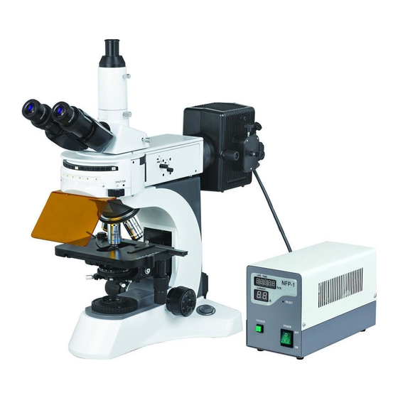
BestScope International Limited 1.Components Name ●FL-800 Epi-fluorescent Attachment includes: ( Fig.1 ① Main body of the Epi-fluorescent Attachment ② Power supply unit NFP-1 ③ Power cord (please use the power cord provided) ④ A GCQ-100 mercury burner ⑤ Fuses (8A) ④... -
Page 25: Assembly
BestScope International Limited 2. Assembly ● BS-7000A Laboratory Fluorescent Microscope= (BS-2080)+(FL-800) ③ ② ① Assembly of BS-7000A Laboratory Fluorescent Microscope: Loosen the setscrew① and take the trinocular Viewing Head ③ from the body of BS-2080 laboratory microscope. Insert the epi-fluorescent attachment into the laboratory microscope correctly and tighten the setscrew①... - Page 26 BestScope International Limited 2.1 Preparation Open the box carefully, remove all packing material and take the attachment out. 2.2 Mounting the Mercury Burner ① (Fig.1 and Fig.2) 1.Loosen the burner socket clamping screw ①, and remove the burner socket.(fig.1) 2 . After removing the foam backstop ② , securely Fig.1...
- Page 27 ), cause the burner to explode. ⑥ ● It is better to use the power cord provided by ④ BestScope and the same type power cord should be used if you lose or damage the old one. Fig. 7...
-
Page 28: Adjustment & Operation
BestScope International Limited 2.7 Fuse Replacement (Fig.7 and Fig. 8) Set the main switch ④ to “O” ( OFF ) and unplug the power cord before replacing fuses. Using a flat-blade screwdriver, remove each of the fuses holders ⑦ by tuning it counter- clockwise。... - Page 29 BestScope International Limited ND filters Fig.10 Fluorescent mirror block (filter block ) ◎ There are 6 fluorescent mirror blocks (filter block) mounted in the filterblock turret at the most.(fig.11) ● a mirror block includes a diachronic mirror, a barrier filter, an excitation filter.(There are kinds of excitation filters).Don’t take apart the filer...
- Page 30 BestScope International Limited Power Supply Unit (for 100w mercury lamp) Hour counter Ammeter Start reset button Main switch 1: ON 0: OFF Fig.12 Frequency switch Lamp housing connector Fuse holders Power cord connector Voltage switch Fig.13...
- Page 31 BestScope International Limited 3.2 Operation 3.2.1 Preparation 1 . Verify that the voltage and the frequency of the AC mains outlet match the setting of the voltage switch and the frequency switch on the rear of the power supply units.
- Page 32 BestScope International Limited DM570 BP510-550 BA590 ·Rhodamine, TRITC: Fluorescent antibody method ·Propidium iodide: DNA ·RFP 3.2.3 Objectives for Various Observations OBJECTIVES EXCIATION B, G U, V, B, G 4×/0.13 Fluorescent Objective ○ ○ 10×/0.30 Fluorescent Objective ○ ○ 40×/0.75 Fluorescent Objective ○...
- Page 33 BestScope International Limited ③ ② ① Fig.1 Adjusting the field iris diaphragm (Fig.2) The field diaphragm adjusts the diameter of the illuminating beam to obtain good image contrast. Keeping the field diaphragm stopped down to the smallest required area for each observation makes it possible to prevent color fading of areas outside the observation target region.
- Page 34 BestScope International Limited 3.2.6 CenteringtheApertureIrisDiaphragm (Fig.3) 1. Switch the light shutter① to “●”position to shut off the light path. 2.Revolve the filter block turret to engage the G-excitation mirror block or another into the light path. ③ 3 . Switch the light shutter① to“O” position to open the light path.
- Page 35 BestScope International Limited 3.2.7 Centering the mercury burner ② (Fig.4-6) ③ ◎Before proceeding to center the burner, wait for the arc image to stabilize to protect against glare during arc image centering, it should be ① viewed across the excitation light protective shield.
- Page 36 BestScope International Limited Centering the mirror reflected image (Fig.6) ★ The mirror reflected image has been centered before leaving the factory. Do not adjust the knob ⑦ please if not necessary. Only when the burner has been centered precisely, can ⑥...
-
Page 37: Troubleshooting Guide
BestScope International Limited Note When the hour counter indicates ”100.0”,set Hour counter the main switch to “o”( OFF) for safety, wait for more than 10 minutes, then replace the Ammeter lamp burner after making sure that the lamp housing has cooled down.. - Page 38 BestScope International Limited The objective is improperly engaged Make sure nosepiece clicks in the light path properly into place The fluorescent mirror block is Engage it properly in the light path 3. The edge of the field of improperly engaged in the light path view is obscured or not The field of view doesn’t open fully...
-
Page 39: Characteristics Of Mirror Block's Wavelength
BestScope International Limited 5. Characteristics of Mirror Block’s wavelength Blue excitation Green excitation Ultraviolet excitation Violet excitation... -
Page 40: Technical Specifications
BestScope International Limited 6. Technical Specifications Fluorescent Filter Excitation Dichroic mirror Barrier Filter block B Excitation BP460~490 DM500 BA520 ● Epi-Fluorescent Illumination G Excitation BP510~550 DM570 BA590 ● U Excitation BP330~385 DM400 BA420 ○ V Excitation BP400~410 DM455 BA455 ○...
Need help?
Do you have a question about the BS-7000A and is the answer not in the manual?
Questions and answers