
Related Manuals for Microhard Systems pDDL900


Summary of Contents for Microhard Systems pDDL900
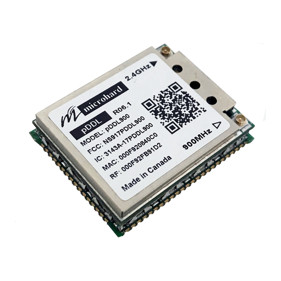
- Page 1 Operating Manual pDDL900 1W Dual Frequency 900MHz/2.4GHz Digital Data Link Revision 0.35, April 11, 2017 Microhard Systems Inc. www.microhardcorp.com...
-
Page 2: Proprietary Rights
Warranty Microhard Systems Inc. warrants that each product will be free of defects in material and workmanship for a period of one (1) year for its products. The warranty commences on the date the product is shipped by Microhard Systems Inc. Microhard Systems Inc.’s sole liability and responsibility under this warranty is to repair or replace any product which is returned to it by the Buyer... - Page 3 WARNING: Changes or modifications not expressly approved by Microhard Systems Inc. could void the user’s authority to operate the equipment. This device has been tested with UFL to Reverse Polarity SMA connectors with the antennas listed in Appendix A When integrated in OEM products, fixed antennas require installation preventing end-users from replacing them with non-approved antennas.
-
Page 4: Pddl900 Exigences Réglementaires
. WARNING: Les changements ou modifications non expressément approuvés par Microhard Systems Inc. pourraient annuler l'autorité de l'utilisateur à utiliser l'équipement . Ce dispositif a été testé avec MCX et connecteurs SMA à polarité inverse sur les antennes répertoriées à... - Page 5 Federal Communication Commission Interference Statement This equipment has been tested and found to comply with the limits for a Class B digital device, pursuant to part 15 of the FCC Rules. These limits are designed to provide reasonable protection against harmful interference in a residential installation.
- Page 6 Co-Location with Cellular Modems FCC: The maximum calculated MPE ratio for the EUT with 2.5 dBi dipole antenna is 0.398 (evaluated at 36 cm), this configuration can be co-located with other antennas provided the sum of the MPE ratios for all the other simultaneous transmitting antennas incorporated in a host device is <...
-
Page 7: Table Of Contents
Contents Warranty ..................................ii Proprietary Rights ................................. ii pDDL900 Regulatory Requirements .......................... iii pDDL900 Exigences Réglementaires ...........................iv Co-Location Instructions ..............................vi GENERAL ................................1 ................................ 1 RODUCT VERVIEW ..............................2 UTPUT OWER EVEL INSTALLATION ..............................3 ..................................3 VERVIEW ............................3... -
Page 9: General
The small-size and superior RF performance of this module make it ideal for many applications. While a pair of pDDL900 modules can link two terminal devices (“point-to- point” operation); multiple modules can be used together to create a network of various topologies, including “point-to-multipoint”... -
Page 10: Output Power Level
While the typical application for the pDDL900 is to provide a short- to mid- range wireless communications link between DTEs, it can be adapted to almost any situation where an asynchronous serial interface is used and data intercommunication is required. -
Page 11: Installation
3. Installation 3.0 Overview The pDDL900 complies with FCC part 15 at the modular level for operation in the license-free 902-928 MHz and 2400-2483.5 MHz ISM band. This chapter provides guidelines for installing and deploying equipment which incorporates the pDDL900 module. - Page 12 Figure 1 Gain Calculation The power level has been set to 30dBm (1W) on the transmitter, and the receiver sensitivity for the pDDL900 is -108dBm. System gain would be calculated to be: 30 - 2 + 6 + 3 - 2 + 108 = 143 dB.
-
Page 13: Antennas And Cabling
-95dBm. 3.2 Antennas and Cabling This section describes the recommended procedure for installing cabling and antennas for use with the pDDL900 module. 3.2.1 Internal Cabling The most common method for installing the module is to run a cable from the module’s UFL connector to a reverse TNC bulkhead connector on the... -
Page 14: Installing External Cables, Antennas And Lightning Arrestors
Typically, both ports on surge arrestors are N-female. External Filter Although the pDDL900 is capable of filtering out RF noise in most WARNING: environments, there are circumstances that require external filtering. Paging towers and cellular base stations in close proximity to the pDDL900 Direct human contact with the antenna can desensitize the receiver. - Page 15 Appendix A. antenna with appropriate gain. See appendix A for a list of approved antennas that can be used with the pDDL900 radio modem. If you require another type of antenna WARNING: please contact Microhard Systems Inc. The pDDL900 CANNOT be Be careful with dBi vs dBd gains used with any antenna that does not appear in Appendix A.
- Page 16 Example 1) What is the maximum power the pDDL900 can be set to comply with FCC and IC given the following equipment given a Rubber Ducky Ant Gain 2dBi and no cable or connectors in the system? Max EIRP 36dBm Max TX power = EIRP –...
- Page 17 6 dBi, 2.4GHz Omni Directional Antenna RPTNC Pigtail MHS031340 8 dBi, Omni Directional Antenna RPTNC Pigtail MHS034020 10.5 dBi, 2.4GHz Omni Directional Antenna RPTNC Pigtail MHS034030 12 dBi, 2.4GHz Omni Directional Antenna RPTNC Pigtail MHS034040 15 dBi, 2.4GHz Omni Directional Antenna RPTNC Pigtail pDDL900 Operating Manual...
- Page 18 WARNING: Changes or modifications not expressly approved by Microhard Systems Inc. could void the user’s authority to operate the equipment. This device has been tested with UFL connectors with the antennas listed in Appendix A When integrated in OEM products, fixed antennas require installation preventing end-users from replacing them with non-approved antennas.
Need help?
Do you have a question about the pDDL900 and is the answer not in the manual?
Questions and answers