Advertisement
Quick Links
+050000740 - rel. 1.3 del 18.04.2013
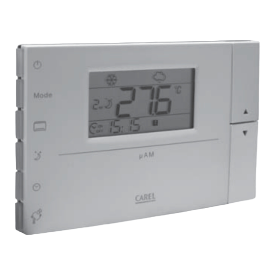
ADE***10** µAM
– Controllore per µe-dronic / µe-dronic controller
Schema di collegamento esemplifi cativo/Example connection diagram
MCH200*03*
ADDRESS= 199
MCH2004850
GND
+
HYSC00F0P0
+
GND
I/0 BOARD 1...
ADDRESS= 1
HYFC000000
HYSC00F0P0
...I/0 BOARD 10
ADDRESS= 10
HYFC000000
e
M od
Vista inferiore
Lower view
Descrizione
µAM è un dispositivo che gestisce, tramite rete RS485, un sistema micro idronico costituito da un µChiller
É dotato di una sonda di temperatura interna e, a seconda dei modelli, di sonda di umidità e orologio.
Istruzioni per il montaggio e l'installazione
Togliere l'alimentazione prima di intervenire sul µAM in fase di montaggio, manutenzione e sostituzione.
La distanza dei fori di montaggio è studiata per poter fi ssare il µAM ad una scatola da incasso conforme alle normative CEI C.431 - IEC 670.
Se questa non è presente, usare i fori di montaggio sul guscio come guida per la foratura sul muro e utilizzare poi il kit di viti e tasselli in
dotazione.
Il terminale deve essere fi ssato a muro in modo da permettere il ricircolo dell'aria attraverso le feritoie del guscio posteriore. Evitare i luoghi
dove la misura della temperatura ambiente può essere alterata, come ad esempio muri esterni, nelle vicinanze di porte verso l'esterno o in
esposizione al sole.
I cavi di collegamento devono passare attraverso il foro presente nel centro del guscio posteriore del µAM ed essere fi ssati ai morsetti posti
sul guscio stesso.
Per accedere ai morsetti di connessione è necessario sganciare il guscio posteriore facendo leva sull'apposita linguetta. L'apertura e la
chiusura del µAM devono avvenire applicando un movimento "a cerniera" facendo perno sul lato superiore dello strumento e sollevando
quello inferiore (vedi Fig. 2). Utilizzare capicorda adatti per i morsetti in uso. Allentare ogni vite ed inserirvi i capicorda, quindi serrare le viti.
Ad operazione ultimata tirare leggermente i cavi per verifi carne il corretto serraggio.
In fase di chiusura fare attenzione che i perni sulla scheda si infi lino nei corrispondenti morsetti, e che i cavi non ostacolino l'operazione.
Nota: Adottare precauzioni contro le scariche elettrostatiche nel maneggiare la scheda, evitando di avvicinarsi con le dita ai componenti
elettronici montati sulle schede.
Connessioni di alimentazione
Rispettare le seguenti prescrizioni:
• I terminali di alimentazione del µAM sono chiamati G e G0. La connessione avviene tramite morsetti a vite a 2 vie fi ssati sul retro a muro
dello strumento;
• Un fusibile obbligatorio dedicato da 250 mAT deve essere posto esternamente tra l'alimentazione ed il terminale G;
• Utilizzare un alimentatore o un trasformatore di sicurezza in classe 2 di almeno 4 VA, che garantiscano un isolamento doppio o rinforzato
tra la rete a tensione pericolosa ed il terminale;
• Se il trasformatore o alimentatore utilizzato per il µAM è lo stesso che alimenta anche il controllo collegato tramite linea seriale (µChiller
allora il terminale G0 del µAM deve essere collegato al terminale G0 del µChiller
• Nel caso in cui sia richiesta la messa a terra di un terminale di alimentazione, deve essere messo a terra il terminale G0 (e NON il
terminale G), sia per il µAM sia per gli altri dispositvi presenti.
Connessioni interfaccia seriale
GND
Per il collegamento seriale in RS485 ai controllori di tipo µChiller
Rx/Tx+
G0
conduttori di tipo AWG20-22 e lunghezza totale non superiore a 1000 m. Il cavo deve essere adatto a reti RS485 e avere una capacità tra i
Rx/Tx-
G
conduttori non superiore a 90 pF/m. Il cavo deve essere collegato ai morsetti chiamati TX+, TX- (doppino) e GND (schermo). La linea deve
essere realizzata a bus come da Fig. 1. Collegare, inoltre, una resistenza di terminazione da 120 ohm all'estremo della linea opposto al µAM.
Attenzione: la linea seriale può essere connessa solamente a circuiti SELV.
Possono essere collegati i dispositivi CAREL con i seguenti codici: MCH200*03* con opzione MCH2004850 (Rs485) e HYFC00000* con
opzione HYSC00F0P0 (RS485).
24 Vac
GND
+
Confi gurazione dispositivi
Prima di avviare l'impianto è necessario assicurarsi che tutti i parametri dei dispositivi µChiller
correttamente. Particolare attenzione deve essere posta al settaggio degli indirizzi che devono essere 1-10 per e-drofan (P69) e 199 per il
µChiller
2
SE (H10). Si ricorda che le caratteristiche del µAM dipendono dalla confi gurazione di µChiller
accurata dei parametri coinvolti consultare i manuali relativi.
Avvertenze generali
• Evitare l'installazione delle schede in ambienti che presentino le seguenti caratteristiche:
• umidità relativa maggiore di quanto indicato;
• forti vibrazioni o urti;
• esposizione a getti d'acqua;
• esposizione ad atmosfere aggressive ed inquinanti (es.: gas solforici e ammoniacali, nebbie saline, fumi) con conseguente corrosione
e/o ossidazione;
• elevate interferenze magnetiche e/o radiofrequenze (ad esempio vicino ad antenne trasmittenti);
• esposizione all'irraggiamento solare diretto e agli agenti atmosferici in genere;
• ampie e rapide fl uttuazioni della temperatura ambiente;
• ambienti ove sono presenti esplosivi o miscele di gas infi ammabili;
• esposizione alla polvere (formazione di patina corrosiva con possibile ossidazione e riduzione dell'isolamento).
Fig. 1
• Per pulire il display usare un panno morbido. Non usare acqua o solventi;
• L'uso a temperature particolarmente basse può causare una visibile diminuzione della velocità di risposta del display. Questo è da
ritenersi normale e non è indice di malfunzionamento;
• Una tensione di alimentazione elettrica diversa da quella prescritta può danneggiare seriamente il sistema;
• Separare i cavi del µAM da cavi che alimentano carichi induttivi e di potenza per evitare possibili disturbi elettromagnetici. Non inserire
mai nelle stesse canaline (comprese quelle dei cavi elettrici) cavi di potenza e cavi di comunicazione seriale. Evitare che i cavi di
comunicazione siano installati nelle immediate vicinanze di dispositivi di potenza (contattori, dispositivi magnetotermici o altro);
• Qualora l'apparecchio venisse adoperato in un modo non specifi cato dal costruttore, la protezione prevista dall'apparecchio potrebbe
essere compromessa.
Interfaccia utente
La tabella riportata di seguito illustra le operazioni fondamentali svolte dai tasti del µAM in condizioni di funzionamento normale:
Icona
Nome
POWER
MODE
Mode
FANCOIL
SLEEP
CLOCK
(1)
TEMP
UP, DOWN
,
(1)
Imposta l'ora se non era mai stata regolata (solo se presente l'orologio opzionale).
(2)
Solo se presente la sonda di umidità (versioni ADEF*, ADEG*, ADEH*).
Fig. 2
2
SE e da più fancoil (e-drofan).
2
SE;
2
SE ed e-drofan utilizzare un doppino ritorto schermato, con sezione dei
2
SE, e-drofan e µAM siano stati confi gurati
2
SE e e-drofan, per una descrizione
Descrizione
On/Off impianto(e-drofan e µChiller
2
SE), mantiene abilitate le fascie orarie
Impostazione la modalità di funzionamento (estate, inverno, auto, deumidifi ca manuale)
Impostazione singola del setpoint e On/Off di ogni e-drofan
Attivazione/disattivazione modalità notturna e modifi ca del tempo rimanente
Attivazione/disattivazione fasce orarie
Visualizzazione temporanea informazioni alternative (sonda e setpoint di umidità
(2)
)
Accesso visualizzazione e modifi ca parametri
Incremento/decremento setpoint di temperatura (con Ch02= 2 o con Co01= 2)
Description
µAM is a device that manages a micro hydronic system via a RS485 network. It is made up of a µChiller
fan). It is fi tted with an internal temperature probe, depending on the model as well as a humidity probe and clock
Instructions for assembly and installation
Disconnect the power before carrying out work on the µAM at the assembly, maintenance and replacement stages.
The distance of the assembly holes has been researched to fi x the µAM to a wall box that complies with CEI C.431 – IEC 670 standards.
If this is not there, use the assembly holes on the casing as a guide to make the holes in the wall and then use the screw and plug kit
provided.
The terminal must be fi tted to the wall in order to allow for air re-cycling via the openings on the back casing. Avoid places where the
surrounding temperature may be altered, for example external walls, near doors facing outside or areas exposed to the sun.
The connection cables must go through the hole in the centre of the µAM's back casing and be fi tted to the clamps on the casing itself.
In order to access the connection clamps, one has to unhook the back casing by lifting up the specifi c fl ap. The opening and closure of
the µAM must be done by applying a "hinge" movement, making a bolt on the upper side of the instrument and lifting the lower one
(see Fig. 2). Use cable ends that suit the terminals. Loosen each screw and insert the cable ends, then tighten the screws. Once the
operation is fi nished, tug the cables lightly to check they are tight enough.
Make sure the bolts on the card, at the closure stage, fi t into the corresponding clamps and that the cables are not obstructing the
operation.
Note: Adopt precautions against electrostatic discharges when handling the card, keeping your fi ngers well clear of the electronic parts
fi tted to the cards.
Feeder connections
Comply with the following instructions:
• The µAM power terminals are called G and G0. The connection is made via screw clamps with 2 routes fi xed to the back of the
instrument wall;
• A specifi c 250 mAT obligatory fuse must be placed externally between the feeder and the G terminal;
• Use a feeder or cat. 2 safety transformer with at least 4 VA, that guarantee a double insulation or reinforcement between the
dangerous voltage network and the terminal;
2
SE),
• If the transformer or feeder used for the µAM is the same as the one that also powers the control linked via the serial line (µChiller
then the µAM's G0 terminal must be linked to the µChiller
2
SE's G0 terminal;
• If a feeder terminal has to be earthed, then the G0 (and NOT the G terminal) must be earthed both for the µAM and for other devices
there.
Serial interface connections
For the serial connection in RS485 to the µChiller
2
SE and e-drofan controllers, use a shielded twisted duplex cable, with AWG20-22
conductor section and overall length of 1000 m. The cable must be adapted to the Rs485 network and have a capacity between the
conductors of no more than 90 pF/m. The cable must be connected to the clamps known as TX+, TX- (duplex cable) and GND (shield).
The line must be bus created as shown in Fig. 1. Furthermore, connect a 120 ohm termination resistance to the far end of the opposite
line to the µAM
Warning: the serial line can only be connected to SELV circuits. The CAREL devices can be connected using the following codes:
MCH200*03* with option MCH2004850 (RS485) and HYFC00000* with option HYFC00F0P0 (RS485).
Device confi guration
Before starting up the plant, make sure that all the µChiller
2
SE, e-drofan and µAM device parameters have been correctly set. Pay
particular attention when setting the addresses which must be 1-10 for e-drofan (P69) and 199 for the µChiller
the µAM characteristics depend on the µChiller
2
SE and e-drofan confi guration. See the relative manuals for an accurate description of the
parameters.
General warnings
• Avoid installing the cards in places with the following characteristics:
• relative humidity higher than that indicated;
• heavy vibrations or knocks;
• exposure to jets of water;
• exposure to aggressive and polluting atmospheric agents (e.g.: sulphur and ammonia gases, saline mist, smoke) which may cause
corrosion and/or oxidation;
• high magnetic and/or radio frequency interference (e.g. near transmitting antennas);
• exposure to direct sunlight and atmospheric agents in general;
• large and rapid fl uctuations in the surrounding temperature;
• environments where explosives or mixes of fl ammable gases are found;
• exposure to dust (formation of corrosive patina with possible oxidation and reduction of insulation);
• Use a soft cloth to clean the display. Do not use water or solvents
• Usage at particularly low temperatures can cause a visible reduction in the display's reply speed. This is perfectly normal and should
not be seen as a fault;
• An electrical power voltage different from the one required, can seriously damage the system;
• Separate the µAM cables from those that feed inductive and power loads, in order to avoid possible electromagnetic interference.
Never lay power cables (including the electrical cables) and serial communication cables into the same conduits. Make sure the
communication cables are not installed close to the power devices (meters, circuit-breaker devices or other);
• Should the apparatus be handled differently from the manufacturer's specifi cations, the apparatus' in-built protection could be
compromised.
User interface
The table below shows the essential operations carried out by the µAM keys under normal working conditions:
Icon
Name
Description
POWER
On/Off system (e-drofan and µChiller
Mode
MODE
Set the operating mode (summer, winter, auto, manual dehumidifi cation)
FANCOIL
Single setting of the setpoint and On/Off of each e-drofan
SLEEP
Activation/disabling of night mode and changing the remaining time
CLOCK
(1)
Activation/disabling of time slots
TEMP
Temporary viewing of alternative information (humidity probe and setpoint
Access to view and change parameters
UP, DOWN
Increase/decrease the temperature setpoint (with Ch02= 2 o con Co01= 2)
,
(1)
Set the time if it has never been adjusted (only if there is a clock provided as optional).
(2)
Only if there is a humidity probe (ADEF*, ADEG*, ADEH* versions).
2
SE and several fan coils (e-dro-
2
SE),
2
SE (H10). Remember that
2
SE), keeps the time slots active
(2)
)
Advertisement

Related Manuals for Carel ADE 10 Series


Summary of Contents for Carel ADE 10 Series
- Page 1 Possono essere collegati i dispositivi CAREL con i seguenti codici: MCH200*03* con opzione MCH2004850 (Rs485) e HYFC00000* con Warning: the serial line can only be connected to SELV circuits. The CAREL devices can be connected using the following codes: opzione HYSC00F0P0 (RS485).
- Page 2 fi nal product to malfunction; CAREL accepts no liability in such cases. The customer must use the product only in the manner described in the documentation relating to the product. The liability of CAREL in relation to its products is specifi...
Need help?
Do you have a question about the ADE 10 Series and is the answer not in the manual?
Questions and answers