Table of Contents
Advertisement
Available languages
Available languages
Quick Links
DB2000 Series Mounting Base Installation Sheet
EN DA DE ES FR IT
1
EN: Installation Sheet
Description
This document includes installation information for DB2002,
DB2002U, DB2004, and DB2016 bases.
Installation
Caution:
For general guidelines on system planning, design,
installation, commissioning, use and maintenance, refer to the
EN 54-14 standard and local regulations.
Polarity must be observed to ensure full functionality with all
compatible devices.
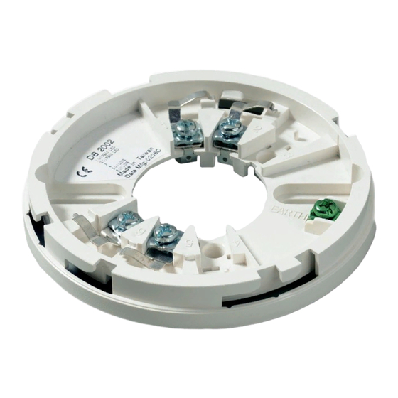
See Figure 1 for DB2002, DB2002U, DB2004, and DB2016
mounting bases.
1.
Earth shield (optional)
2.
Loop driver
3.
Loop driver return (Class A wiring only)
4.
Remote indicator
5.
DB2002 / DB2004 base with 2000 Series detector
6.
DB2016 Isolating Base with 2000 Series detector
© 2021 Carrier. All rights reserved.
NL PL PT RO SV TR
DB2002 and DB2004 bases for 2000 Series detectors
Terminal connections are as follows:
•
Terminal 1 – Remote indicator (positive)
•
Terminal 2 – Remote indicator (negative)
•
Terminal 5 – Line in / out (positive)
•
Terminal 6 – Line in / out (negative)
DB2016 Isolating Base for 2000 Series detectors
Terminal connections are as follows:
•
Terminal 1 – Remote indicator (positive)
•
Terminal 2 – Remote indicator (negative)
•
Terminal 5 – Line in / out (positive)
•
Terminal 6 – Not used
•
Terminal 7 – Line in (negative)
•
Terminal 8 – Line out (negative)
Maintenance
Basic maintenance consists of a yearly inspection. Do not
modify internal wiring or circuitry.
Testing the isolator
To test the isolator, provoke a short circuit in the loop and
check that the corresponding LED is activated.
1 / 16
P/N 10-4227-501-DB20-06 • ISS 23JUL21
Advertisement
Table of Contents

Related Manuals for Aritech DB2000 Series


Summary of Contents for Aritech DB2000 Series
- Page 1 DB2000 Series Mounting Base Installation Sheet EN DA DE ES FR IT NL PL PT RO SV TR DB2002 and DB2004 bases for 2000 Series detectors EN: Installation Sheet Terminal connections are as follows: • Terminal 1 – Remote indicator (positive) Description •...
-
Page 2: Specifications
Specifications Declaration of 360-4227-0699 performance number DB2002, DB2002U, and DB2004 Product identification DB2016 Number of terminals: Intended use See the product Declaration of Performance Earth contact Declared performance See the product Declaration of Performance Remote indicator option EN 54 EN 54-17:2005 + AC:2007 IP Rating IP30 Operating temperature... -
Page 3: Tekniske Specifikationer
DB2002 og DB2004 sokkel for 2000 serie detektorer DB2016 Terminal forbindelserne er som følger: Fjernindikation Tæthedsklasse IP30 • Terminal 1 – Fjernindikation ( + ) Driftstemperatur −10 til +55ºC • Terminal 2 – Fjernindikation ( − ) Opbevaringstemperatur −10 til +70ºC Relativ luftfugtighed Ikke-kondenserende 10 til 95% •... -
Page 4: Wartung
Technische Daten DE: Installationsanweisungen DB2002, DB2002U und DB2004 Sockel Anzahl der Klemmen: Beschreibung Erdungsanschluss Dieses Dokument enthält Informationen zur Installation der Parallelanzeigeanschluss folgenden Sockel DB2002, DB2002U, DB2004 und DB2016. IP-Schutzklasse IP30 Betriebstemperatur −10 bis +55ºC Installation Lagerungstemperatur −10 bis +70ºC Relative Luftfeuchtigkeit Nicht kondensierend 10 bis 95% Warnung:... -
Page 5: Mantenimiento
Zócalos DB2002/DB2004 con detector de la serie 2000 Erklärung der 360-4227-0699 Performance-Nummer Zócalo aislante DB2016 con detector de la serie 2000 Produkt code DB2016 Zócalos DB2002 y DB2004 para detectores de la serie 2000 Beabsichtigte Siehe Produkt Erklärung der Performance Verwendung Las conexiones son las siguientes: Wesentlichen... - Page 6 Advertencias y declaraciones sobre el DB2016 producto Resistencia de línea 0,1 Ω Número de terminales ESTOS PRODUCTOS ESTÁN DESTINADOS A LA VENTA E INSTALACIÓN POR UN PROFESIONAL DE SEGURIDAD Toma de tierra Sí EXPERIMENTADO. CARRIER FIRE & SECURITY B.V. NO Opción de indicador remoto Sí...
-
Page 7: Maintenance
Certification et conformité Base DB2016 avec isolateur Les connexions du bornier sont: Cette section constitue un résumé de la déclaration des performances. Cette dernière est établie conformément au • Borne 1 – Indicateur d’action (ligne à polarité positive) règlement (UE) 305/2011 relatif aux produits de construction, •... -
Page 8: Installazione
Specifiche tecniche IT: Istruzioni di installazione Basi DB2002, DB2002U e DB2004 Numero di morsetti: Descrizione Contatto di terra Il presente documento contiene informazioni per le basi tipo Opzione indicatore remoto Si (DB2002, DB2004) DB2002, DB2002U, DB2004 e DB2016. Grado di protezione IP30 Temperatura di funzionamento da −10 a +55ºC... - Page 9 DB2002 / DB2004 montagevoet met 2000 series detector Numero della 360-4227-0699 Dichiarazione di DB2016 isolator montagevoet met 2000 series detector Prestazione Codice prodotto DB2016 DB2002 en DB2004 montagevoet voor 2000 series detectors Uso previsto Vedi la Dichiarazione di Prestazione del prodotto Klem aansluitingen zijn als volgt: Caratteristiche...
- Page 10 Zie voor meer informatie over DB2016 isolator montagevoet garantiebepalingen en productveiligheid Lijn weerstand 0.1Ω https://firesecurityproducts.com/policy/pro Aantal aansluitklemmen duct-warning/ of scan de QR-code: Aardklem Neven indicator mogelijkheid PL: Instrukcja instalacji IP waarde IP30 Bedrijfstemperatuur −10 tot +55ºC Opslagtemperatuur −10 tot +70ºC Relatieve luchtvochtigheid Zonder condensatie 10 tot 95% Opis...
- Page 11 Test izolatora Producent Thunderous Sounders Electronics Co. Ltd., No, 21, Kai Fe 3rd, Pao En Industrial Area, W celu przetestowania urządzenia należy zewrzeć pętlę, na Ren De Village, Tainan, Taiwan, R.O.C. której jest zainstalowane, co powinno spowodować aktywację Autoryzowany przedstawiciel producenta na izolatora oraz diody LED, która znajduje się...
-
Page 12: Especificações Técnicas
Deve ser observada a polaridade por forma a assegurar a Bases DB2002, DB2002U e DB2004 funcionalidade total com todos os dispositivos compatíveis. Peso DB2002 38 g Figura 1 indica as ligações para as bases DB2002, DB2004, e DB2002U 98 g DB2016. - Page 13 Informações de contacto e documentação • Conectorul 5 – Intrare/ieșire linie (pozitiv) do produto • Conectorul 6 – Intrare/ieșire linie (negativ) Para obter informações de contacto ou para transferir a Soclu izolator DB2016 pentru detectoare seria 2000 documentação mais recente do produto, visite firesecurityproducts.com.
- Page 14 SV: Installationsanvisning Culoare Albă Dimensiuni Ø 100 × 13 mm Greutate 49 g Beskrivning Informaţii de reglementare Det här dokumentet innehåller installationsinformation för följande produkter DB2002, DB2002U, DB2004, och DB2016 Această secțiune furnizează un rezumat privind performanța sockel. declarată în conformitate cu Regulamentul privind produsele de construcții (UE) 305/2011 și Regulamentele delegate Installation (UE) 157/2014 și (UE) 574/2014.
- Page 15 Tekniska data Produktkod DB2016 Avsedd användning Se produktens prestandadeklaration DB2002, DB2002U och DB2004 Viktiga kännetecken Se produktens prestandadeklaration Anslutningar: EN 54 EN 54-17:2005 + AC:2007 Jordanslutning Remote LED Ja (DB2002, DB2004) Kontaktuppgifter och IP rating IP30 produktdokumentation Driftstemperatur −10 till +55ºC Förvaringstemperatur −10 till +70ºC För kontaktuppgifter eller för att ladda ned den senaste...
-
Page 16: Teknik Özellikler
2000 Serisi dedektörler için DB2002 ve DB2004 tabanlar DB2016 Terminal bağlantıları şu şekildedir: Uzak gösterge seçeneği Evet IP koruma sınıfı IP30 • Terminal 1 – Uzak gösterge (pozitif) Çalışma sıcaklığı −10 ila +55ºC • Terminal 2 – Uzak gösterge (negatif) Depolama sıcaklığı...
Need help?
Do you have a question about the DB2000 Series and is the answer not in the manual?
Questions and answers