Advertisement
Quick Links
Advertisement

Related Manuals for Monitech ML121PN5000


Summary of Contents for Monitech ML121PN5000
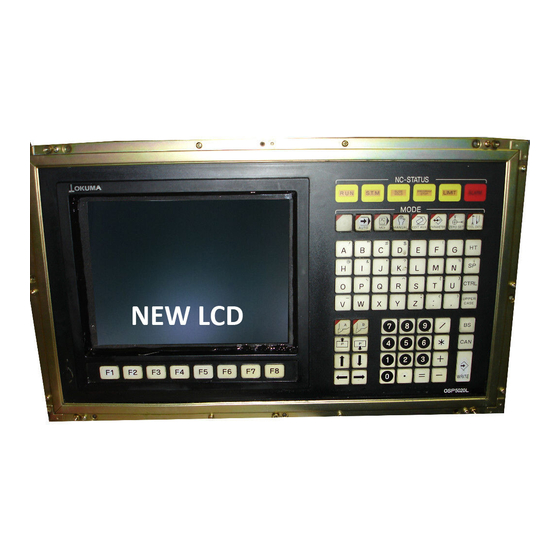
- Page 1 INSTALL GUIDE ML121PN5000 & ML121PN5020 LCD upgrade for Okuma OSP 5000 & 5020 M20A03-PN5020/5000...
-
Page 2: Warranty
IMPORTANT: WARRANTY Before using any MONITECH product please carefully review this Manual as well as any additional documentation provided with your shipment. Attempting any of the following will void product warranty: • unauthorized repairs or parts replacement • inappropriate use or placement: exposing product to liquids, harmful gases, electrical shock, physical shock, temperatures beyond the range of -4°F to... - Page 3 REMOVALE: Step #1) Turn off turn off main power, turn off machine. Step #2) Remove mounting screws securing the CRT chassis. Remove chassis from control panel. Disconnect video power connector. Note its location and polarity. Disconnect video signal cable. Note its location and polarity.
- Page 4 Step 3) This disassembly has many various sized screws. The screws are best to be sorted using a multi-sectional storage box. Remove the top and back covers and disconnect the fan - 8 Screws. Remove the top and back covers and disconnect the fan - 8 Screws. BEFORE AFTER Step...
- Page 5 Step 5) Discharge the CRT tube. Using a large flat screwdriver, with a well-insulated handle, connect a clip of the anode lead, to a good chassis ground. Connect the wire to the screwdriver shaft, electrical tape is fine. With the wire grounded and being careful not to touch any metal with your hands, pry the screwdriver under the rubber anode cap, and contact the wire inside.
- Page 6 Step 7) Follow the below instructions. 1) Remove Left Side Small Housing, (4 Screws). Remove Left Side Small Housing, (4 Screws). 2) Remove CRT main housing. (7 screws). Lift out the entire CRT and chassis. Remove CRT main Lift out the entire housing.
- Page 7 Step #8) Remove the front plastic bezel. There are 2 different bezels between OSP 5000 and OSP 5020. OSP 5000, does not have the user controls in the Bezel. Unscrew the fasteners holding the bezel in place. BEFORE AFTER OSP 5020, has the user controls in the bezel. Unscrew the fasteners holding the user controls in place.
-
Page 8: Installation
INSTALLATION: Step 9) Take the Monitech monitor out of the box depending on your application. OSP 5000 or OSP 5020. Step 10) Mount your Monitech Monitor at the front of your HMI where the front bezel was before removal. Use the MK2005 to mount OSP 5000 And MK2007 to mount OSP 5020. - Page 9 MK2007. And place the stick where your F keys were. Use this hardware to mount the user controls. Place sticker on top of the metal of your Monitech Monitor to represent the F Keys REV.A NOV 2019...
- Page 10 Step 12) Determine what type of video connector you have. Monochrome (Edge Connector) or Color (20 Pin connector) Edge Connector (Monochrome) 20 Pin Connector (Color) For Edge Connector use the MCPB003 Install guide. M20A03-PN5020/5000...
- Page 11 For 20 Pin Connector use the MAV535, MAP305 & MAP307. Step 13) Install CRT main housing. (7 screws). Fasten CRT main housing. (7 screws). REV.A NOV 2019...
- Page 12 14) Position Monitor Face Down and screw in the wire from the Power Supply: Install power supply by screwing in 4 screws. Step #15) Before you put the HMI with your new Monitech Monitor back into your machine. Test & adjust the image. After mount back into your machine.
- Page 13 Enjoy your rejuvenated Monitor. Call us to order more replacement HMI parts. Keep your OKUMA HMI’s up and running! ML121LL14JB-12.1" LCD ML080QTLB12S - LCD Upgrade Upgrade for Okuma Kit for 9" Okuma LB12 Totoku CD14JBS with 14" CRT MDT-1005 CRT MT700L-TOUCH MP7000 - LCD Replacement for SCREEN FOR...
- Page 14 For Technical Support, Call 1-877-493-6105 Support@Monitech.com M20A03-PN5020/5000...
- Page 15 20 Howard Place Kitchener, Ontario N2K 4Z4 CANADA 519.725.222 www.monitech.com REV.A NOV 2019...
- Page 16 M20A03-PN5020/5000...
Need help?
Do you have a question about the ML121PN5000 and is the answer not in the manual?
Questions and answers