Table of Contents
Advertisement
Advertisement
Table of Contents

Related Manuals for Power smart PS5045


Summary of Contents for Power smart PS5045
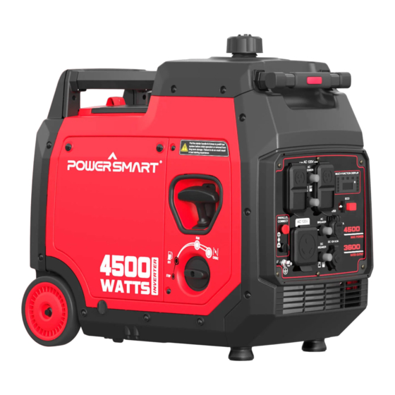
- Page 1 INSTRUCTION MANUAL 4500W Inverter Generator Model # PS5045 Have product questions or need technical support? Please scan the QR code to enter our official website and contact us! Website:www.powersmartusa.com Toll free: 1-800-791-9458 M-F 9-5 EST Website Email: support@amerisuninc.com...
-
Page 3: Table Of Contents
Storage & transport procedures…………………………………………. 22 Troubleshooting…………………………………………………………. 23 Wiring diagram…………………………………………………………. 24 Exploded view & parts list……………………………………………… 25 Warranty statement……………………………………………………… 30 TECHNICAL DATA 4500W Inverter Generator Model#PS5045 Engine type: 4 stroke, OHV, single cylinder with forced air-cooling system Start type: Manual Phase:... -
Page 4: Introduction
INTRODUCTION Thank You for Purchasing a PowerSmart® Product. This manual provides information regarding the safe operation and maintenance of this product. Every effort has been made to ensure the accuracy of the information in this manual. PowerSmart® reserves the right to change this product and specifications at any time without prior notice. -
Page 5: General Safety Rules
GENERAL SAFETY RULES For any questions regarding the hazard and safety notices listed in this manual or on the product, please call (800) 791-9458 Mon-Fri 9-5 EST before using the generator. Please read and understand the instructions in this manual before starting the engine or attempting to operate this unit. DANGER: CARBON MONOXIDE Using a generator indoors CAN KILL YOU IN MINUTES. -
Page 6: Important Safety Instructions
WARNING: This generator produces heat when running. Temperatures near exhaust can exceed 150℉ (65℃). Do not touch hot surfaces. Pay attention to warning labels on the generator identifying hot parts of the machine. Allow generator to cool down after use before touching engine or areas of the generator that become hot during use. -
Page 7: Symbols
SYMBOLS Some of the following symbols may be used on this product. Please study them and learn their meaning. Proper interpretation of these symbols will allow you to operate the product better and safer. SYMBOL NAME DESIGNATION/EXPLANATION Volts Voltage Amperes Current Hertz Frequency (cycles per second) -
Page 8: Knowing Your Generator
KNOWING YOUR GENRATOR Use the illustrations below to become familiar with the locations and functions of the various components and controls of this generator... - Page 9 Overload indicator (red) When the overload indicator is on, it indicates that the generating set is overload and then the AC protector works. It will stop the output of generating set to protect the electric equipment and the generating set itself. At this time, the running indicator (green) is off and the overload indicator (red) is on, but the engine is still in running state.
- Page 10 Rest button The reset button is used to restore output if an overload occurs. To restore output, reduce the loads and press the rest button. Energy-saving switch When the energy-saving switch is in “ON” position, the energy saving equipment controls the engine rotate speed according to the connected loads.
- Page 11 Off: Fuel off without stop. This position can run out of the remaining fuel and improve the reliability of the generating set. Note: If you do not plan to use the generator in the near future, please use this function, or drain the fuel inside the carburetor through the carburetor drain bolt.
-
Page 12: Generator Preparation
Fuel tank cap Remove the fuel tank cap by rotating it anticlockwise. Telescoping handle When moving the generator, please hold the telescoping handle and press the button on it, and pull it outward. Note: Before moving, please turn off the generator and fuel switch. Please move the generator on a relatively flat ground. - Page 13 High altitude This generating set may require a high altitude carburetor kit to ensure correct operation at high altitudes. Consult the authorized local dealer for high altitude kit information if you always operate your engine at altitudes above 5,000 feet (1,500 meters). CAUTION: Even with carburetor modification, generating set horsepower will decrease about 3.5% for each 1,000 feet (300 meters) increase in altitude.
- Page 14 Place the engine on a level surface with engine stopped. Check the engine oil level. Remove the oil maintenance cover. Remove the dipstick and wipe it clean. Reinstall dipstick into hole, rest on oil fill neck, DO NOT thread cap into hole. ...
- Page 15 IMPORTANT: Do not fill tank indoors. Do not fill tank when the engine is running or hot. Never use an oil/gasoline mixture. Never use old gasoline. Avoid getting dirt or water into the fuel tank. Gasoline can age in the tank and make starting difficult.
-
Page 16: Starting The Generator
STARTING THE GENERATOR CAUTION: Disconnect all electrical loads from the generator before attempting to start. Pull the starter handle 6-8 times to prefill fuel system before initial operation or removal from long term storage. Failure to do so could result in bad starting experience. 1. - Page 17 CONNECT TO ELECTRICAL DEVICES 1. Inspect power cord for damage before using. There is a hazard of electrical shock from crushing, cutting or heat damage. 2. Make sure that the generating set has been properly grounded. If the electric devices require grounding, the generating set must ground.
-
Page 18: Stopping The Generator
PARALLEL OPERATION Make sure that the generating set is in a good running state before connecting it to other generating sets. The total power of electric devices should not exceed rated power of generating set. When electric motor starts, the overload indicator (red) will light up and normally it will stop within 4 seconds. - Page 19 MAINTENANCE SCHEDULE Stop the generating set before serving, disconnect all electric devices and battery (If equipped),and cool down the generating set completely. Serve the generating set in a clean, dry and flat area, so that no accident would happen during the serving. Please make the wheel in brake state to stop accidental movement of generating set.
- Page 20 GENERATING SET MAINTENANCE WARNING: Never clean the generator when it is running! Never use water to clean the generating set. Water can enter the generating set through the cooling slots and damage the generating set windings. WARNING: Do not modify the generator in any way. Do not tamper with governed speed. Generator supplies correct rated frequency and voltage when running at factory set.
- Page 21 5. Fully tighten the drain bolt before reinstalling the drain plug. 6. Add recommended oil to the upper limit. 7. Fully tighten the dipstick and install the air filter maintenance cover back in place. 8. Properly dispose of any used oil at an approved waste management facility. AIR FILTER WARNING: Do not run the engine without the air filter, or serious danger can result.
-
Page 22: Storage & Transport Procedures
SPARK ARRESTER 1. Allow the generating set to cool completely before servicing the spark arrester. 2. Remove the muffler blind window first. 3. Remove the spark arrester screen. 4. Carefully remove the carbon deposits from the spark arrester screen with a wire brush. -
Page 23: Troubleshooting
TROUBLESHOOTING... -
Page 24: Wiring Diagram
WIRING DIAGRAM... -
Page 25: Exploded View & Parts List
EXPLODED VIEW & PARTS LIST Generator exploded view... - Page 26 Generator parts list Item Stock# Description Qty. Item Stock# Description Qty. 100011533-0005 Bolt, M6×22 100122169 Muffler 100011539-0001 Bolt, M6×45 100011422-0004 Nut, M8 Inverter 100087975 100006526 Gasket, Muffler Protective Cover 100162760-0001 Control Panel 100079483-0001 Nut, M8 100011265-0003 Bolt, M6×18 1ZZDDF037 Engine 100093717 Inverter 100087976-0002...
- Page 27 Engine exploded view...
- Page 28 Engine parts list Item Stock# Description Qty. Stock# Description Qty. 100011264-0003 Bolt, M6×16 100030062 Motor Base 100056645 Valve Cover 100033258 Guide Clamp 100713739 Breather Hose 100052405 Spring Gasket, Valve 100010181 100005137 Clamp Cover Rocker Arm Fuel Hose 100004419 100017699 Assembly φ4×φ10×320 100050881 Rocker Arm Base...
- Page 29 Item Stock# Description Qty. Item Stock# Description Qty. Gasket, 100010148 100130948 Lower Shield Crankcase Oil Seal, 100010550 Pin,φ8×14 100017644 φ25×φ41.25×6 100010761 Bearing, TM6205 100000655 Clip 100099599 Camshaft 100135644 Stator Assembly 100126476 Crankshaft 100126953 Rotor 100010577 Woodruff Key 100087582 Cooling Fan 100062919 Oil Sensor 100087581...
-
Page 30: Warranty Statement
PowerSmart is committed to building equipment that will provide years of dependable service. Our warranties are consistent with our commitment and dedication to quality. THREE (3) YEARS LIMITED WARRANTY OF POWER SMART PRODUCTS FOR HOME USE. PowerSmart (“Seller") warrants to the original purchaser only, that all PowerSmart consumer power tools will be free from defects in material or workmanship for a period of three (3) years from date of purchase.
Need help?
Do you have a question about the PS5045 and is the answer not in the manual?
Questions and answers