Craftsman PGT9000 Operator's Manual
Hide thumbs
Also See for PGT9000:
- Operator's manual (100 pages) ,
- Operator's manual (100 pages) ,
- Operator's manual (104 pages)
Table of Contents
Advertisement
Available languages
Available languages
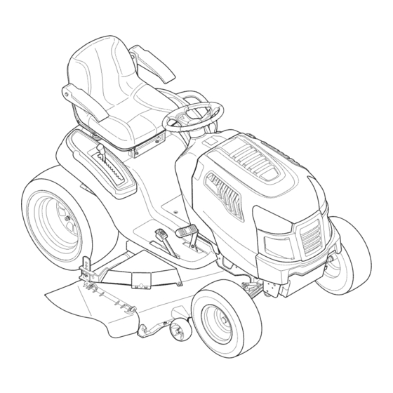
Operator's Manual
GArdEn TrACTOr
28 HP, 54" Tractor
Electric Start
PGT9000
Model No. 247.289842
• Español, p. 63
This product has a low emission engine which operates differently
from previously built engines. Before you start the engine, read and
understand this Operator's Manual.
IMPOrTAnT:
read and follow all Safety
rules and Instructions before
operating this equipment.
Sears Brands Management Corporation, Hoffman Estates, IL 60179 U.S.A.
Visit our website: www.craftsman.com
For answers to your questions about
this product, Call:
1-800-659-5917
Craftsman Tractor Help Line
5am - 5 pm, Mon - Sat
Form No. 769-06507A
(January 7, 2011)
Advertisement
Table of Contents

Related Manuals for Craftsman PGT9000


Summary of Contents for Craftsman PGT9000
- Page 1 Safety 1-800-659-5917 rules and Instructions before operating this equipment. Craftsman Tractor Help Line 5am - 5 pm, Mon - Sat Sears Brands Management Corporation, Hoffman Estates, IL 60179 U.S.A. Visit our website: www.craftsman.com Form No. 769-06507A...
-
Page 2: Table Of Contents
WARRANTY SERVICE For warranty coverage details to obtain free repair or replacement, call 1-800-659-5917 or visit the web site: www. craftsman.com In all cases above, if part repair or replacement is impossible, the riding equipment will be replaced free of charge with the same or an equivalent model. -
Page 3: Safety Instructions
SAFETY InSTrUCTIOnS WARNINg DANgER This machine was built to be operated according to the safe opera- This symbol points out important safety instructions which, if not tion practices in this manual. As with any type of power equipment, followed, could endanger the personal safety and/or property of carelessness or error on the part of the operator can result in serious yourself and others. - Page 4 SAFETY InSTrUCTIOnS SLOPE OPERATION • Slow down before turning. Operate the machine smoothly. Avoid erratic operation and excessive speed. Slopes are a major factor related to loss of control and tip-over • Disengage blade(s), set parking brake, stop engine and wait until accidents which can result in severe injury or death.
- Page 5 SAFETY InSTrUCTIOnS CHILDREN SERVICE Tragic accidents can occur if the operator is not alert to the presence Safe Handling of Gasoline of children. Children are often attracted to the machine and the mowing To avoid personal injury or property damage use extreme care in activity.
- Page 6 SAFETY InSTrUCTIOnS General Service • Do not change the engine governor settings or over-speed the engine. The governor controls the maximum safe operating speed • Never run an engine indoors or in a poorly ventilated area. Engine of the engine. exhaust contains carbon monoxide, an odorless, and deadly gas.
- Page 7 SAFETY InSTrUCTIOnS SAFETY SYMbOLS This page depicts and describes safety symbols that may appear on this product. Read, understand, and follow all instructions on the machine before attempting to assemble and operate. Symbol Description READ THE OPERATOR’S MANUAL(S) Read, understand, and follow all instructions in the manual(s) before attempting to assemble and operate DANGER—...
-
Page 8: Slope Guide
SAFETY InSTrUCTIOnS SLOPE gUIDE... -
Page 9: Safety Labels
SAFETY LABELS WARNINg This symbol points out important safety instructions which, if not followed, could endanger the personal safety and/or property of yourself and others. Read and follow all instructions in this manual before attempting to operate this machine. Failure to comply with these instructions may result in personal injury. -
Page 10: Assembly
ASSEMBLY TRACTOR SET-UP Shipping brace Removal WARNINg Moving The Tractor Manually Your tractor’s transmission is equipped with a hydrostatic relief valve Make sure the garden tractor’s engine is off, set the parking brake for occasions when it is necessary to move the tractor manually. Open- and remove the ignition key before removing the shipping brace. - Page 11 ASSEMBLY Connecting the battery Cables Checking Tire Pressure WARNINg WARNINg Battery posts, terminals, and related accessories contain lead and Never exceed the maximum inflation pressure shown on the sidewall lead compounds, chemicals known to the State of California to cause of the tire.
- Page 12 ASSEMBLY Setting the Deck gauge Wheels and Roller gasoline and Oil Move the tractor on a firm and level surface, preferably pavement, and The fuel tank is located under the hood. Remove the fuel cap by proceed as follows turning it counterclockwise. Use only clean, fresh (no more than 30 days old), unleaded gasoline.
-
Page 13: Know Your Lawn Mower
KnOW YOUr MOWEr Systems Indicator Monitor Ignition Switch Fuel Tank Cap Module Throttle Control PTO (Blade Engage) Knob Fuel Level Indicator Drive Pedal Brake Pedal Parking Brake/ Reverse Pedal Cruise Control Lever Deck Lift Lever Seat Adjustment Lever Cup Holder Figure 6 THROTTLE CONTROL LEVER The Garden Tractor controls and features are illustrated in Figure 6... - Page 14 KnOW YOUr MOWEr DECk LIFT LEVER SYSTEMS INDICATOR MONITOR/HOUR METER LCD Found on your tractor’s right fender, the deck lift lever is used to change the height When the ignition key is of the cutting deck. To use, move the lever rotated out of the STOP to the left, then place in the notch best position but not into the START...
- Page 15 KnOW YOUr MOWEr PTO / bLADE ENgAgE kNOb FUEL LEVEL INDICATOR Activating the PTO engages power to the cutting The Fuel Level Indicator is located on the left side of the tractor’s deck or other (separately available) attachments. dash and indicates the amount of fuel in the gas tank. Pull outward on the PTO/Blade Engage knob to activate it.
-
Page 16: Operation
OPErATIOn SAFETY INTERLOCk SWITCHES STOPPINg THE ENgINE This tractor is equipped with a safety interlock system for the protection WARNINg of the operator. If the interlock system should ever malfunction, do not If you strike a foreign object, stop the engine and disconnect the operate the tractor. - Page 17 OPErATIOn REVERSE CAUTION MODE DRIVINg ON SLOPES The REVERSE CAUTION MODE position of the key switch module Refer to the SLOPE GUIDE on page 8 to help determine slopes where allows the tractor to be operated in reverse with the blades (PTO) you may operate the tractor safely.
- Page 18 OPErATIOn MOWINg Cruise Control WARNINg WARNINg Never engage the cruise control lever while traveling in reverse. To help avoid blade contact or a thrown object injury, keep bystand- ers, helpers, children and pets at least 75 feet from the machine while To set the cruise control: it is in operation.
-
Page 19: Service And Maintenance
SErVICE And MAInTEnAnCE WARNINg Before performing any type of maintenance/service, disengage all Follow the maintenance schedule given below. This chart describes controls and stop the engine. Wait until all moving parts have come to service guidelines only. Use the Service Log column to keep track of completed maintenance tasks. - Page 20 SErVICE And MAInTEnAnCE NOTE: References to the right or left side of tractor are from the NOTE: If there is too much tension on the belt for it to be easily re- moved from the electric PTO clutch, carefully insert a 3⁄8” drive ratchet viewpoint of the operator facing forward from the tractor seat.
- Page 21 SErVICE And MAInTEnAnCE CHANgINg THE TRANSMISSION DRIVE Remove the bowtie cotter pin connecting the deck sway rod to the tractor frame. See Figure 13. bELT Several components must be removed and special tools used in order to change the tractor’s transmission drive belt. See a Sears or other qualified service dealer to have the transmission drive belt replaced.
- Page 22 SErVICE And MAInTEnAnCE To place the new belt, begin by routing the belt around the two Replace the PTO Pulley belt guard removed in step 4 of CUT- outer spindle pulleys, then around the front spindle pulley as TING DECK REMOVAL. shown in Figure 16.
- Page 23 SErVICE And MAInTEnAnCE jump Starting To properly sharpen the cutting blades, remove equal amounts of metal from both ends of the blades along the cutting edges, WARNINg parallel to the trailing edge, at a 25° to 30° angle. Always grind each cutting blade edge equally to maintain proper blade balance.
- Page 24 SErVICE And MAInTEnAnCE FUSE Attach the hose coupler to the water port on your deck’s surface. See Figure 20. WARNINg Before servicing, repairing, or inspecting, always disengage PTO (Blade Engage knob), set parking brake, stop engine and remove key to prevent unintended starting. A fuse is installed in your tractor’s wiring harness to protect the trac- tor’s electrical system from damage caused by excessive amperage.
- Page 25 SErVICE And MAInTEnAnCE ADjUSTMENTS Front Wheels Each of the front wheel axles and rims is equipped with a grease WARNINg fitting. See Figure 21. Lubricate with a No. 2 multi-purpose grease Shut the engine off, remove the ignition key and engage the parking applied with a grease gun after every 25 hours of tractor operation.
- Page 26 SErVICE And MAInTEnAnCE Leveling the Deck (Side to Side) Steering Adjustment If the cutting deck appears to be mowing unevenly, a side to side If the tractor turns tighter in one direction than the other, or if the ball adjustment can be performed. Adjust if necessary as follows: joints are being replaced due to damage or wear, the steering drag links may need to be adjusted.
- Page 27 SErVICE And MAInTEnAnCE DECk REAR ROLLER ADjUSTMENT ENgINE MAINTENANCE The rear rollers on the mower deck are not designed to carry the Checking the Engine Oil weight of the deck. The rear rollers should be adjusted to approxi- Only use high quality detergent oil rated with API service classification mately 1⁄4”...
- Page 28 SErVICE And MAInTEnAnCE Changing the Engine Oil Remove the air filter cover. To remove the air filter, lift the end of the filter. See Figure 28. WARNINg Cover If the engine has been recently run, the engine, muffler and sur- rounding metal surfaces will be hot and can cause burns to the skin.
- Page 29 SErVICE And MAInTEnAnCE Fuel Filter Muffler WARNINg WARNINg Gasoline and its vapors are extremely flammable and explosive. Fire Temperature of muffler and nearby engine areas may exceed 150˚ F or explosion can cause severe burns or death. (65˚C). Avoid contact with these areas. •...
-
Page 30: Off-Season Storage
OFF-SEASOn STOrAGE WARNINg Never store garden tractor with fuel in tank indoors or in poorly ventilated areas where fuel fumes may reach an open flame, spark, or pilot light as on a furnace, water heater, clothes dryer, or gas appliance. PREPARINg THE ENgINE PREPARINg THE gARDEN TRACTOR IMPORTANT: Fuel left in the fuel tank during warm weather deterio-... -
Page 31: Troubleshooting
TrOUBLESHOOTInG WARNINg Before performing any type of maintenance/service, disengage all controls and stop the engine. Wait until all moving parts have come to a complete stop. Disconnect spark plug wire and ground it against the engine to prevent unintended starting. Always wear safety glasses during operation or while performing any adjustments or repairs. - Page 32 TrOUBLESHOOTInG Mower will not mulch grass Engine speed too low. Place Throttle control in FAST (rabbit) position. Wet grass. Do not mulch when grass is wet. Excessively high grass. Mow once at a high cutting height, then mow again at desired height or make a narrower cutting swath. Dull blade.
- Page 33 PrOTECTIOn AGrEEMEnT Congratulations on making a smart purchase. Your new Craftsman® Once you purchase the Agreement, a simple phone call is all that it product is designed and manufactured for years of dependable opera- takes for you to schedule service. You can call anytime day or night, or tion.
-
Page 34: Parts List
PArTS LIST Steering and Axle — Model No. 247.289842... - Page 35 PArTS LIST Steering and Axle — Model No. 247.289842 Ref. Ref. Part No. Description Part No. Description 710-04095 Hex Head Screw, 3/8-16:1.00 938-04041-0637 LH Axle Assembly 710-0514 Hex Head Screw, 3/8-16:1.00 710-0395 Hex Head Screw, 5/16-18:2.25 710-0643 Hex Head Screw, 5/16-18:1.00 710-0859 Hex Head Screw, 3/8-16:2.50 711-04998...
- Page 36 PArTS LIST Hood and Dash — Model No. 247.289842...
- Page 37 PArTS LIST Hood and Dash — Model No. 247.289842 Ref. Ref. Part No. Description Part No. Description 631-04353P Dash Lever 731-07458 RH Lens 710-04484 Taptite Screw, Lock Washer, 5/16-18:.750 731-07459 LH Lens 710-0599 Taptite Screw, Lock Washer, 1/4-20:0.500 931-07461 Hood Scoop 710-0895 Hi-Lo Screw, Lock Washer, 1/4-15:0.750 731-07467...
- Page 38 PArTS LIST Seat and Fender — Model No. 247.289842 83-06181 racket...
- Page 39 PArTS LIST Seat and Fender — Model No. 247.289842 Ref. Ref. Part No. Description Part No. Description 683-04301-0637 Lift Shaft Assembly 732-04563 Compression Spring, .68 x 1.065 x .055 712-04063 Flangelock Nut, 5/16-18 938-0296 Shoulder Screw, .437 x .268:5/16-18 712-04065 Flangelock Nut, 3/8-16 783-06049-0691 Seat Mounting Bracket 914-0104...
- Page 40 PArTS LIST Drive and Rear Wheels — Model No. 247.289842 29 33 62 54...
- Page 41 PArTS LIST Drive and Rear Wheels — Model No. 247.289842 Ref. Ref. Part No. Description Part No. Description 918-04317 Wheel Assembly Hub 747-05124 Brake Rod 918-04917 Transmission 747-05125A Control Rod 710-0189 Hex Screw, 5/16-18:3.00 747-05130 Disengage Rod 710-0227 Screw, #8-18:0.500 747-05181 Belt Keeper, 5/16 710-04484...
- Page 42 PArTS LIST Engine Accessories — Model No. 247.289842...
- Page 43 PArTS LIST Engine Accessories — Model No. 247.289842 Ref. Part No. Description 683-04549-0637 Mulffler Shield Assembly 710-0227 Screw, Indented Washer, #8-18:0.500 710-04683 Taptite Screw, Indented Washer, 3/8-16:1.000 710-0599 Taptite Screw, Indented Washer, 1/4-20:0.500 710-1314A Socket Head Screw, 5/16-18:.750 712-0271 Sems Nut, 1/4-20 721-0460 Exhaust Gasket 725-0157...
- Page 44 PArTS LIST PTO and battery — Model No. 247.289842...
- Page 45 PArTS LIST PTO and battery — Model No. 247.289842 Ref. Part No. Description 710-04379A Hex Head Screw, 7/16-20:3.50 917-1774C Electric PTO Clutch 725-0157 Cable Tie, 3/16 x .05 x 7.4 936-0171 Lock Washer, 7/16 736-0277 Flat Washer, 1.031 x 1.620 x .095 756-0978B Electric PTO Engine Pulley 683-04469B-0691 Frame...
- Page 46 PArTS LIST Deck — Model No. 247.289842...
- Page 47 PArTS LIST Deck — Model No. 247.289842 Ref. Ref. Part No. Description Part No. Description 12650 Height Adjust Bracket 732-04652 Compression Spring, .535 OD x 1.751 LG 96606 Retainer Hook Bracket 732-04692 Extension Spring, .85 OD x 5.915 LG 918-04608A Spindle Assembly 732-0934 Extension Spring, 1.15 OD x 5.99 LG...
- Page 48 PArTS LIST Craftsman Engine Model 49M777-0853-g5 For Model 247.289842 48 SHORT BLOCK 1058 OPERATOR’S MANUAL 1329 REPLACEMENT ENGINE 1330 REPAIR MANUAL 1373 1028 1366 601A 1374 1017 1027 552A 552A 1024 219 221...
- Page 49 PArTS LIST Craftsman Engine Model 49M777-0853-g5 For Model 247.289842...
- Page 50 PArTS LIST Craftsman Engine Model 49M777-0853-g5 For Model 247.289842 1026 1026A 1022 1029 1100 1023 1022 1022 1029 1100 1023A 1022...
- Page 51 PArTS LIST Craftsman Engine Model 49M777-0853-g5 For Model 247.289842 1169 1128 1124A 1126 1124 1436 1437 1127 1438 318A...
- Page 52 PArTS LIST Craftsman Engine Model 49M777-0853-g5 For Model 247.289842 1036 EMISSIONS LABEL 1040 305A 186A 186B 306A 918A 186A 307A 447A...
- Page 53 PArTS LIST Craftsman Engine Model 49M777-0853-g5 For Model 247.289842 1054 668A 1059 1070 1005 1119 789A 1051 1439 1090...
- Page 54 PArTS LIST Craftsman Engine Model 49M777-0853-g5 For Model 247.289842 121 CARBURETOR OVERHAUL KIT 1123 358 ENGINE GASKET SET 1022 1095 VALVE GASKET SET 1022...
- Page 55 PArTS LIST Craftsman Engine Model 49M777-0853-g5 For Model 247.289842 Ref. No. Part No. Description Ref. No. Part No. Description 96908 Cylinder Assembly 691056 Washer (Flywheel) 690718 Screw (Throttle Valve) 499585 Bushing/Seal Kit (Magneto Side) 699721 Kit-Idle Speed 391086s Seal-Oil (Magneto Side)
- Page 56 PArTS LIST Craftsman Engine Model 49M777-0853-g5 For Model 247.289842 Ref. No. Part No. Description Ref. No. Part No. Description 794389 Collector-Oil 696541 Drive-Starter 691024 Clamp-Casing 796530 Hose-Oil Drain 792629 Screw (Casing Clamp) 692024 Clutch-Drive 695410 Washer-Sealing 691036 Dipstick 792651 Washer (Governor Control Lever)
- Page 57 PArTS LIST Craftsman Engine Model 49M777-0853-g5 For Model 247.289842 Ref. No. Part No. Description Ref. No. Part No. Description 493880s Terminal-Spark Plug 1127 695407 Screw (Float Bowl) 865A 792286 Cover-Air Guide (Valley) 1128 690990 Screw (Carburetor Nozzle) 690968 Seal-Valve 1169...
- Page 58 LABELS 777I23379 777D14493 777I23356 777I23323 777D14480 777X43688 777S30503 777X44429 777S33183 777I22265 777S33660 777I23357 777D14486 777D14487...
- Page 59 Look For Relevant Emissions Durability Period and Air Index Information On Your Engine Emissions Label Engines that are certified to meet the California Air Resources Board (CARB) Tier 2 Emission Standards must display information regarding the Emissions Durability Period and the Air Index. Sears Brands Management Corporation makes this information available to the consumer on our emission labels.
- Page 60 (This page applicable in the U.S.A. and Canada only.) Sears brands Management Corporation (Sears), the California Air Resources board (CARb) and the United States Environmental Protection Agency (U.S. EPA) Emission Control System Warranty Statement (Owner’s Defect Warranty Rights and Obligations) EMISSION CONTROL WARRANTY COVERAGE IS APPLICABLE TO CERTI- YEAR 1997 AND LATER ENGINES WHICH ARE PURCHASED AND USED FIED ENGINES PURCHASED IN CALIFORNIA IN 1995 AND THEREAF-...
- Page 61 FEDERAL and/or CALIFORNIA EMISSION CONTROL WARRANTY STATEMENT YOUR WARRANTY RIgHTS AND ObLIgATIONS MTD Consumer Group Inc, the United States Environmental Protection Agency (EPA), and, for those products certified for sale in the state of California, the California Air Resources Board (CARB) are pleased to explain the emission (evaporative and/or exhaust) control system (ECS) warranty on your outdoor 2006 and later small off-road spark-ignited engine and equipment (outdoor equipment engine) In California, new outdoor equipment engines must be designed, built and equipped to meet the State’s stringent anti-smog standards (in other states, 1997 and later model year equipment must be designed, built, and equipped to meet the U.S.
- Page 62 WARRANTED PARTS: The repair or replacement of any warranted part otherwise eligible for warranty coverage may be excluded from such warranty coverage if MTD Consumer Group Inc demonstrates that the outdoor equipment engine has been abused, neglected, or improperly maintained, and that such abuse, neglect, or improper mainte- nance was the direct cause of the need for repair or replacement of the part.
-
Page 63: Español
Funcionamiento ....... 77 dECLArACIÓn dE GArAnTÍA CRAFTSMAN PROFESIONALES DE gARANTÍA POR DOS AÑOS a partir de la fecha de compra, todas las partes no fungibles de este equipo de equitación están garantizados contra cualquier defecto de material o mano de obra. - Page 64 InSTrUCCIOnES dE SEGUrIdAd ADVERTENCIA PELIgRO Esta máquina fue construida para ser operada de acuerdo con La presencia de este símbolo indica que se trata de instrucciones las reglas de seguridad contenidas en este manual. Al igual que importantes de seguridad que se deben respetar para evitar con cualquier tipo de equipo motorizado, un descuido o error por poner en peligro su seguridad personal y/o material y la de otras parte del operador puede producir lesiones graves.
- Page 65 InSTrUCCIOnES dE SEGUrIdAd • Nunca deje la máquina en funcionamiento sin vigilancia. Apague • Vaya a baja velocidad. Elija una velocidad lo suficientemente baja, siempre las cuchillas, coloque el freno de mano, detenga el motor y de modo que no tenga que detenerse o hacer cambios mientras retire la llave antes de bajarse del vehículo.
- Page 66 InSTrUCCIOnES dE SEGUrIdAd • Para evitar accidentes al operar en marcha atrás, siempre desengan- • Apague todos los cigarrillos, cigarros, pipas y otras fuentes de che las cuchillas antes de colocar marcha atrás. Si está instalado, combustión. el “Modo Precaución Marcha Atrás” (hojas de operar la máquina, •...
- Page 67 InSTrUCCIOnES dE SEGUrIdAd NO MODIFIqUE EL MOTOR • Revise los pernos de montaje de la(s) cuchilla(s) y del motor a intervalos frecuentes para verificar que estén bien apretados. Para evitar lesiones graves o la muerte, no modifique el motor bajo Además, inspeccione visualmente la(s) cuchilla(s) en busca de ninguna circunstancia.
- Page 68 InSTrUCCIOnES dE SEGUrIdAd SÍMbOLOS DE SEgURIDAD Esta página representa y describe la seguridad los símbolos que pueden parecer en este producto. Lea, comprenda, y siga todas instrucciones en la máquina antes procurar para reunir y operar. Symbol Description LEA EL MANUAL(S) DEL OPERADOR leído, entienda, y siga todas las instrucciones en el manual(s) antes de procurar montar y funcionar PELIGRO—...
- Page 69 InSTrUCCIOnES dE SEGUrIdAd...
- Page 70 Esta página se marchó intencionadamente en blanco.
- Page 71 MOnTAJE CONFIgURACIóN DEL TRACTOR Extracción de la traba de seguridad utilizada en el envío Movimiento manual del tractor ADVERTENCIA La transmisión de su tractor viene equipada con una válvula de Asegúrese de que el motor del tractor corta césped esté apagado, coloque el freno de mano y quite la llave de encendido antes de descarga hidrostática para las ocasiones en que sea necesario retirar la traba de seguridad utilizada en el envío.
- Page 72 MOnTAJE CONExIóN DE LOS CAbLES DE LA bATERÍA Control de la presión de los neumáticos ADVERTENCIA ADVERTENCIA Nunca exceda la presión máxima de inflado que se indica en los laterales Los bornes de la batería y los accesorios afines contienen plomo y compues- de los neumáticos.
- Page 73 MOnTAJE Ajuste de las ruedas de calibración de la gasolina y aceite plataforma y rodillo El tanque de combustible está ubicado debajo del capó y tiene una capacidad de tres galones y medio. Quite la tapa de combustible Mueva el tractor a una superficie firme y nivelada, preferentemente girándola en sentido contrario al de las agujas del reloj.
- Page 74 COnOZCA SU COrTAdOrA dE CÉSPEd Monitor del indicador de sistemas Módulo del interruptor de Tapón del tanque de combustible encendido Control del regulador Perilla de potencia de arranque (PTO) (enganche de cuchilla) Indicador de nivel de combustible Pedal de la transmisión Pedal de freno Freno de mano / palanca Pedal de marcha atrás...
- Page 75 COnOZCA SU COrTAdOrA dE CÉSPEd PALANCA DE ELEVACIóN LCD MONITOR INDICADOR DE SISTEMAS/ DE LA CUbIERTA MEDIDOR HORARIO Ubicada en el guardabarros derecho Cuando la llave de encendido del tractor, la palanca de elevación de la se rota fuera de la posición plataforma se utiliza para cambiar la altura STOP (parar) pero no se de la plataforma de corte.
- Page 76 COnOZCA SU COrTAdOrA dE CÉSPEd PERILLA DE POTENCIA DE ARRANqUE (PTO)/ ENgANCHE DE CUCHILLA Al conectar la potencia de arranque (PTO) se suministra alimentación a la plataforma de corte o a otros accesorios (disponibles por separado). Tire hacia afuera de la potencia de arranque/ enganche de cuchilla para activarla.
- Page 77 FUnCIOnAMIEnTO INTERRUPTORES DE bLOqUEO DE SEgURIDAD DETENCIóN DEL MOTOR Este tractor está equipado con un sistema de bloqueo de seguridad ADVERTENCIA para protección del operador. Si el sistema de bloqueo funciona Si golpea contra algún objeto extraño, detenga el motor y desconecte el(los) mal, no se debe hacer funcionar el tractor.
- Page 78 FUnCIOnAMIEnTO MODO DE PRECAUCIóN EN MARCHA ATRáS OPERACIóN EN PENDIENTES La posición MODO DE PRECAUCIóN EN MARCHA ATRÁS del Consulte la sección GUÍA PARA PENDIENTES en la página 68 para módulo de la llave de contacto permite operar el tractor en marcha determinar en qué...
- Page 79 FUnCIOnAMIEnTO CORTE DE CéSPED Control de crucero ADVERTENCIA ADVERTENCIA Nunca enganche la palanca de control de crucero mientras se desplaza en marcha atrás. Para tratar de evitar el contacto con las cuchillas o una lesión por algún objeto que sea arrojado, mantenga a los observadores, a los ayudantes, Para colocar el control de crucero: niños y mascotas alejados al menos 25 metros de la máquina mientras está...
- Page 80 SErVICIO Y MAnTEnIMIEnTO ADVERTENCIA Siga el cronograma de mantenimiento que se presenta a continuación. Antes de realizar cualquier tipo de mantenimiento o servicio, desenganche todos los controles y detenga el motor. Espere a que se Esta tabla sólo describe pautas de servicio. Utilice la columna Registro detengan completamente todas las piezas móviles.
- Page 81 SErVICIO Y MAnTEnIMIEnTO NOTA: Las referencias a la derecha o dejó lado de tractor es del punto NOTA: De haber mucha tensión sobre la correa como para poder extraerla fácilmente del cebador de la PTO eléctrica, inserte de vista del operario frente a delantero del asiento de tractor. cuidadosamente una llave de apriete de trinquete de 3/8 pulgadas ExTRACCIóN DE LA PLATAFORMA DE CORTE (ajustada para...
- Page 82 SErVICIO Y MAnTEnIMIEnTO Mirando la plataforma de corte desde el lado izquierdo del tractor, localice el pasador de soporte de la plataforma ubicado en el lateral posterior izquierdo de la plataforma. Tire hacia afuera el pasador de soporte de la plataforma para Cubierta de Rod Estabilizador separar la misma del brazo de elevación de la plataforma.
- Page 83 SErVICIO Y MAnTEnIMIEnTO Correa de Polea loca la potencia de arranque (PTO) Cubierta de la correa Rotar la polea Varilla del guardacorrea Figura 17 Tornillo con arandela CUCHILLAS DE CORTE hexagonal ADVERTENCIA Figura 15 Apague el motor y extraiga la llave de contacto antes de retirar las Para colocar la correa nueva, comience pasándola alrededor de las dos poleas de husillo externas, luego alrededor de la polea de cuchillas de corte para afilarlas o reemplazarlas.
- Page 84 SErVICIO Y MAnTEnIMIEnTO Arranque con pinzas para batería Para afilar las cuchillas de corte de forma adecuada, extraiga cantidades iguales de metal de ambos extremos de las cuchillas ADVERTENCIA a lo largo de los bordes cortantes, paralelo al borde de caída y a un ángulo de 25°...
- Page 85 SErVICIO Y MAnTEnIMIEnTO FUSIbLE Una el acople de la manguera al puerto de agua que se encuentra en la superficie de la plataforma. Vea la Figura 20. ADVERTENCIA Antes de realizar tareas de mantenimiento, reparaciones o inspecciones, desconecte siempre la PTO (perilla de enganche de cuchillas), coloque el freno de mano, apague el motor y retire la llave, para evitar que alguien encienda accidentalmente el motor.
- Page 86 SErVICIO Y MAnTEnIMIEnTO AjUSTES Ruedas delanteras Cada uno de los ejes y llantas de la rueda delantera viene equipado ADVERTENCIA con un accesorio de engrase. Vea la Figura 21. Lubrique con grasa multiuso Nº 2 aplicada con una pistola de engrase cada 25 horas de Apague el motor, retire la llave de encendido y coloque el freno de funcionamiento del tractor.
- Page 87 SErVICIO Y MAnTEnIMIEnTO Nivelación de la plataforma (lado a lado) Ajuste del volante Si la plataforma de corte estuviera realizando el corte de césped Si le cuesta girar el tractor en una dirección más que en la otra, o si se de forma despareja, puede realizarse un ajuste lado a lado.
- Page 88 SErVICIO Y MAnTEnIMIEnTO AjUSTE DE RODILLOS TRASEROS DE LA MANTENIMIENTO DEL MOTOR PLATAFORMA Control del aceite del motor Los rodillos traseros de la plataforma de corte no han sido diseñados Use solamente un aceite detergente de alta calidad cuya clasificación para soportar el peso de la plataforma.
- Page 89 SErVICIO Y MAnTEnIMIEnTO Cambio de aceite del motor Para extraer el filtro de aire, levante el extremo del filtro. Vea la Figura 28. ADVERTENCIA Filtro de Si el motor se ha puesto en funcionamiento recientemente, el motor, aire silenciador y las superficies metálicas circundantes estarán calientes y pueden causar quemaduras en la piel.
- Page 90 SErVICIO Y MAnTEnIMIEnTO Filtro de combustible Silenciador ADVERTENCIA ADVERTENCIA La gasolina y el vapor de gasolina son sumamente inflamables y La temperatura del silenciador y de las áreas cercanas del motor explosivos. El fuego y las explosiones pueden causar quemaduras puede superar los 150˚F (65˚C).
- Page 91 ALMACEnAMIEnTO FUErA dE TEMPOrAdA ADVERTENCIA Nunca almacene la tractor corta césped con combustible en el tanque en un espacio cerrado o en áreas poco ventiladas donde los gases del combustible puedan llegar a una llama expuesta, una chispa o un piloto como el que tienen algunos hornos, calentadores de agua, secadores de ropa o algún artefacto a gas.
- Page 92 SOLUCIÓn dE PrOBLEMAS ADVERTENCIA Antes de realizar cualquier tipo de mantenimiento o servicio, desenganche todos los controles y detenga el motor. Espere a que se detengan completamente todas las piezas móviles. Desconecte el cable de la bujía y póngalo haciendo masa contra el motor para evitar que se encienda accidentalmente.
- Page 93 SOLUCIÓn dE PrOBLEMAS La cortadora de césped no La velocidad del motor es demasiado lenta. Coloque el control del estrangulador en la posición procesa los recortes como FAST (velocidad rápida, representada por una abono liebre). No procese abono cuando el pasto está mojado. Pasto mojado.
- Page 94 Felicitaciones por haber realizado una adquisición inteligente. El Una vez adquirido el Acuerdo, puede programar el servicio con producto Craftsman® que ha adquirido está diseñado y fabricado tan sólo realizar una llamada telefónica. Puede llamar en cualquier para brindar muchos años de funcionamiento confiable. Pero como momento del día o de la noche o programar un servicio en línea.
- Page 95 nOTAS...
- Page 96 busque el período de duración de emisiones importantes yla información de clasificación de aire en la etiqueta de emisiones de su motor Los motores cuyo cumplimiento con los estándares de emisión Tier 2 de la Comisión de Recursos Ambientales de California (CARB) esté...
- Page 97 (Esta página se aplica sólo en EE.UU. y Canadá). Sears brands Management Corporation, el Consejo de Recursos Ambientales de California (CARb) y la Agencia de Protección Ambiental de los Estados Unidos (EPA) Declaración de garantía del sistema de control de emisiones (derechos y obligaciones de la garantía de defectos del propi- etario) LA COBERTURA DE LA GARANTÍA DE CONTROL DE EMISIONES ES Y PARA LOS MODELOS CERTIFICADOS DEL AÑO 1997 Y POSTERIORES,...
- Page 98 DECLARACIóN FEDERAL y/o DE CALIFORNIA SObRE gARANTÍAS EN EL CONTROL DE EMISIONES SUS DERECHOS Y ObLIgACIONES EN CUANTO A LA gARANTÍA MTD Consumer Group Inc, la Agencia de Protección Medioambiental de los Estados Unidos (EPA), y para aquellos productos certificados para su venta en el es- tado de California, el Departamento de los Recursos del Aire de California (CARB) se complacen en explicar la garantía que cubre al sistema de control (ECS) de emisiones (evaporativas y/o de escape) de su equipo y motor (motor de equipos de exteriores) de encendido por chispa para todo terreno, pequeño, de exteriores del año 2006 y años posteriores En California, los nuevos motores de equipos de exteriores deben estar diseñados, construidos y equipados para cumplir con las...
- Page 99 Durante la totalidad del período de garantía del motor y equipo para todo terreno arriba mencionado, MTD Consumer Group Inc mantendrá un suministro de piezas bajo garantía suficiente para satisfacer la demanda esperada de tales piezas. Cualquier pieza de reemplazo se podrá usar para el cumplimiento del mantenimiento o las reparaciones bajo garantía y se suministrarán sin cargo para el propietario.
- Page 100 1-800-659-5917 Craftsman Help Line www.craftsman.com ® Registered Trademark / Trademark of KCD IP, LLC in the United States, or Sears Brands, LLC in other countries ®...
Need help?
Do you have a question about the PGT9000 and is the answer not in the manual?
Questions and answers