Table of Contents
Advertisement
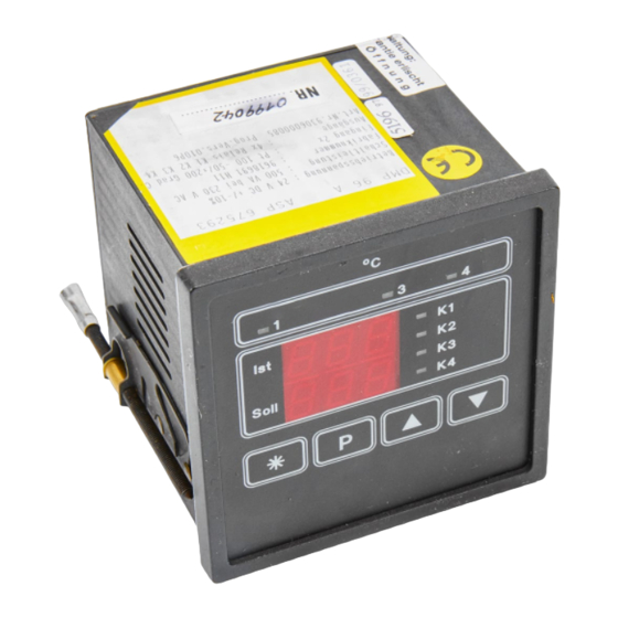
Operating Instructions
Single-channel controller
Program versions:
Before connecting the regulator it is essential to read
this Manual and follow it's instructions.
DOLD GMBH . Blumenstrasse 33 . 70736 Fellbach . Germany
Phone +49 (0)711/95152-0 . Fax +49 (0)711/95152-19 . info@dold-regler.de . www.dold-regler.de
Two-point controller
Continuous-action controller
with one limit-value contact
020H0
020H1
020H2
° C
1
2
3
Ist
Soll
P
DMP 96 A
DMP 96 A
020H3
020H4
020H5
4
K1
K2
(Subject to technical changes)
020H6
020H7
020H8
Advertisement
Table of Contents

Related Manuals for DOLD DMP 96 A


Summary of Contents for DOLD DMP 96 A
- Page 1 Before connecting the regulator it is essential to read this Manual and follow it's instructions. (Subject to technical changes) DOLD GMBH . Blumenstrasse 33 . 70736 Fellbach . Germany Phone +49 (0)711/95152-0 . Fax +49 (0)711/95152-19 . info@dold-regler.de . www.dold-regler.de...
-
Page 2: Table Of Contents
DOLD GMBH Operating instructions DMP 96 A Contents 1. INSTALLING THE CONTROLLER:................ 4 1.1 Directions for installation .......................4 1.2 Identification plate:.........................5 1.3 Connecting the controller: ......................6 1.3.1 Auxiliary power: ..........................6 1.3.2 Terminal connection diagram:....................6 1.4 Mechanical Data:...........................6 2. TECHNICAL DATA, INPUTS:................. 7 2.1 Analog inputs:..........................7... - Page 3 DOLD GMBH Operating instructions DMP 96 A 7. OPERATION:......................13 7.1 Setting parameters on the various levels: ...................13 7.2 The various levels: ........................14 7.3 Setting the setpoint:........................14 7.3.1 Setting the setpoint via the operator level: ................14 7.3.2 Setting the setpoint level via the setpoint entry level: ...............15 7.4 The configuration level: .......................15...
-
Page 4: Installing The Controller
1.1 Directions for installation Important: These directions for the installation of DOLD devices have to be adhered to: If these directions are not adhered to the device may not work accurately, be destroyed or it may result in data being lost. -
Page 5: Identification Plate
Model number Logic input: configurable function Outputs: relay as per order Logic outputs Program version: XXXXX Model No: XXXXXXXXXX Figure 1: DMP 96 A identification plate DMP 96 A Version: Number of pages: 26 Edition: 07.11.2006 H0e020bA4.doc... -
Page 6: Connecting The Controller
6 (-) do not have the same potential! Operating voltage Relay outputs Logic outputs (optional) Figure 2: DMP 96 A connection diagram 1.4 Mechanical Data: Protection class: VDE 0631 Insulation group: C as per DIN VDE 0110 b Type of protection:... -
Page 7: Technical Data, Inputs
DOLD GMBH Operating instructions DMP 96 A Housing: Pull-out housing for mounting control panel per DIN 43 700 with a B fastener as per DIN 43 835 (M 4 screw clamp) Material: PPO, glass-fiber reinforced (Noryl GFN2SE1) self-extinguishing, non-dripping fire protection class UL 94 V1... -
Page 8: Error-Handling At Input
DOLD GMBH Operating instructions DMP 96 A Pt 100 three-wire lead: Automatic line resistance compensation via software (maximum permissible line resistance: 50 Ω per lead) Line resistance correction (line compensation) of max. 9 Ω Pt 100 two-wire lead: possible via software (external bridge clamps 2-3), ≤... -
Page 9: Two-Point Controller
DOLD GMBH Operating instructions DMP 96 A • Continuous-action control response for heating and cooling with PDPID – control character- istic and self-optimization algorithm • Three-point response with adjustable hysteresis • Three-point response with one-sided PDPID – control characteristic and self-optimization al- gorithm 3.1.1 Two-point controller:... -
Page 10: Outputs
DOLD GMBH Operating instructions DMP 96 A Display: Upper 7-segment display Lower 7-segment display Function: Controller current actual value setpoint Actuator current actual value alternation between " -y- " / manipulated variable Outputs: Outputs as per identification plate and accompanying terminal connection diagram: 4.1 Potential-free relay contacts, make contact:... -
Page 11: Output Responses In Cases Of Error
DOLD GMBH Operating instructions DMP 96 A 4.4 Output responses in cases of error: Output response in cases of sensor error: • Relay or logic outputs: Outputs assume the state defined on the configuration level. • Analog output: (continuous-action controller, actual-value output): output U: 0...1 V DC, 0...2 V DC, 0...5 V DC:... -
Page 12: Lower 7-Segment Display
DOLD GMBH Operating instructions DMP 96 A 5.2 Lower 7-segment display shows: • setpoint • parameter value in entry mode • alternation between " -y- " / manipulated variable when actuator function is activated (man- ual function) • alternation between setpoint (auxiliary setpoint) / "Opt" during the self-optimization proce- dure. -
Page 13: Operation
"Er.1" Sensor error message "Er.9" System error message Operation: The operating structure of the DMP 96 A controller includes six separate levels: Setting the setpoint (depending on configuration): • via the operator level. • via the setpoint entry level (by entering a code). -
Page 14: The Various Levels
DOLD GMBH Operating instructions DMP 96 A 7.2 The various levels: Press briefly Operator level (only when function is released) (setpoint setting) Press for 3 s Code Information level (querying of current program number, sensor) (only when function is released) -
Page 15: Setting The Setpoint Level Via The Setpoint Entry Level
DOLD GMBH Operating instructions DMP 96 A Display: Parameter: Range: Factory setting: "SP.2" Setpoint 2 "rA.L...rA.H" 0.0° C (appears only for configuration "Co.L" = 01) " y " Setpoint manipulated variable 0.0...100% 0.0% (appears only for configuration "Aut" = OFF) Display value is accepted When configuring parameter ”Co.u”... - Page 16 DOLD GMBH Operating instructions DMP 96 A Enter code: Confirm code: Display: " Con " Jump to configuration level. Display: Parameter: Range: Factory setting: "Cor" Line compensation and zero-point offset -25...25.0° C 0.0° C "rA.H" Set upper limit of setpoint range max.
- Page 17 DOLD GMBH Operating instructions DMP 96 A Display: Parameter: Range: Factory setting: "Co.2" Configuration of limit-value contact K 2 00...06 Relay deactivated (no function) Absolute limit value of make contact relative to rising temperature Limit value travels with setpoint, make contact relative to rising temp.
- Page 18 DOLD GMBH Operating instructions DMP 96 A Display: Parameter: Range: Factory setting: "An.H" Analog output of actual value max. display end of set- High-end value of measuring range limit range de- point range pendent on dependent sensor ID on sensor ID (Section 2.1)
-
Page 19: Switching Response Of The K 2 Limit-Value Contact
DOLD GMBH Operating instructions DMP 96 A 7.4.1 Switching response of the K 2 limit-value contact: Switching function relative to rising actual value Absolute limit value Limit value changing with setpoint value Actual value X Actual value X Setpoint value "SP.X"... -
Page 20: The Self-Optimization Level
04, 05 7.6 The self-optimization level: The DMP 96 A controller is equipped with an optimization routine for the automatic adaptation of the controller to the controlled system. The optimization algorithm is based on modified Ziegler-Nicols rules, according to which the cha- racteristic data of the system are calculated after an oscillation test in a closed-loop control cir- cuit. - Page 21 DOLD GMBH Operating instructions DMP 96 A Starting and aborting optimization: Optimization can be started or aborted on the self-optimization level (only when function is re- leased). Optimization optimizes for heating or cooling (heating controller or cooling controller, depending on configuration).
-
Page 22: Monitoring The Optimization Process
DOLD GMBH Operating instructions DMP 96 A After completion of the optimization process only the current setpoint appears in the lower dis- play. The calculated parameters are stored in the power-outage-proof EE-PROM, from where they can be retrieved at any time and modified manually. -
Page 23: The Information Level
DOLD GMBH Operating instructions DMP 96 A (°C) (° C) (°C) Pb too small Optimum setting Pb too large Control oscillating slow start-up and poor control (° C) (° C) (° C) Optimum setting Ti too large Ti too small (°... -
Page 24: Line Compensation, Zero-Point Offset
DOLD GMBH Operating instructions DMP 96 A Display: Parameter: "SEn" Sensor ID as in table Sensor ID: Sensor ID by ordering Sensor: Max. display Max. setpoint Display: key: range: range: Pt 100 -69...149° C -50...100° C 3 digits Pt 100 -69...249°... -
Page 25: Error Messages
DOLD GMBH Operating instructions DMP 96 A Error messages: 9.1 Error messages (display): Error display: Cause: Remedy / Explanation: Er. 1 Pt 100 input: Sensor short circuit or Check sensor Lower range limit exceeded, Sensor breakage or Upper range limit exceeded. -
Page 26: Immunity
DOLD GMBH Operating instructions DMP 96 A 11. Immunity: The immunity of the unit was tested with the following interference simulators manufactured by the Schaffner Company (Switzerland). • NSG 222A: Interference pulses with broadband spectrum, short build-up time and low energy ±...
Need help?
Do you have a question about the DMP 96 A and is the answer not in the manual?
Questions and answers