Mitsubishi Electric PEAD Series Service Manual
Split-type, heat pump air conditioners
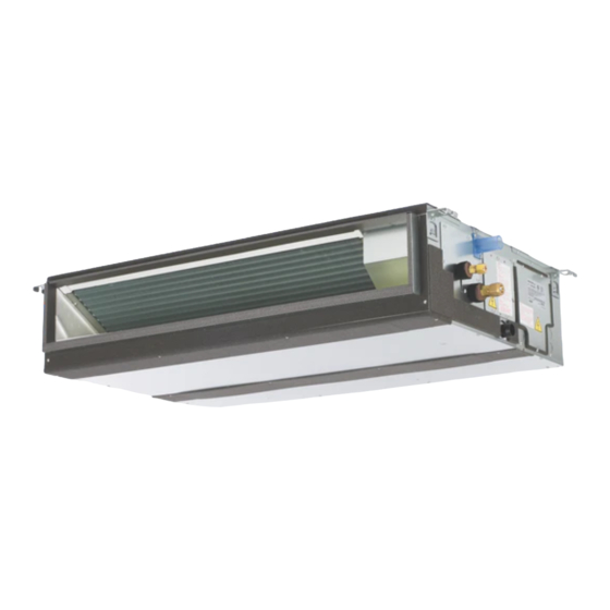
Hide thumbs
Also See for PEAD Series:
- Service manual (60 pages) ,
- Service manual (54 pages) ,
- Service manual (34 pages)
Advertisement
Table of Contents
- 1 Table of Contents
- 2 Safety Precaution
- 3 Part Names and Functions
- 4 Specification
- 5 Fan Performance and Corrected Air Flow
- 6 Sound Pressure Levels
- 7 Outlines & Dimensions
- 8 Wiring Diagram
- 9 Refrigerant System Diagram
- 10 Heater Control
- 11 Humidifier Control
- 12 Erv (Energy Recovery Ventilation) Control
- 13 Troubleshooting
- 14 Disassembly Procedure
- Download this manual
Advertisement
Table of Contents

Related Manuals for Mitsubishi Electric PEAD Series


Summary of Contents for Mitsubishi Electric PEAD Series
-
Page 2: Table Of Contents
CONTENTS 1. SAFETY PRECAUTION ··········································································· 3 2. PART NAMES AND FUNCTIONS ······························································ 5 3. SPECIFICATION ···················································································· 6 4. FAN PERFORMANCE AND CORRECTED AIR FLOW ·································10 5. SOUND PRESSURE LEVELS ·································································17 6. OUTLINES & DIMENSIONS ····································································23 7. WIRING DIAGRAM ················································································25 8. REFRIGERANT SYSTEM DIAGRAM ························································26 9. -
Page 3: Safety Precaution
SAFETY PRECAUTION 1. SAFETY PRECAUTION 1-1. ALWAYS OBSERVE FOR SAFETY Before obtaining access to terminal, all supply circuits must be disconnected. 1-2. CAUTIONS RELATED TO NEW REFRIGERANT Cautions for units utilising refrigerant R410A Use new refrigerant pipes. Do not use refrigerant other than R410A. In case of using the existing pipes for R22, be careful with If other refrigerant (R22 etc.) is used, chlorine in refrigerant the followings. - Page 4 Failure to install and maintain such temperature control mechanism may void the warranty for this unit. • Mitsubishi Electric shall not bear any warranty obligation or other liability for any damage or loss in connection with such third party auxiliary heaters.
-
Page 5: Part Names And Functions
PART NAMES AND FUNCTIONS 2. PART NAMES AND FUNCTIONS • Indoor Unit Air intake (sucks the air inside the room into the unit) Air outlet In case of bottom inlet In case of rear inlet HWE2109A... -
Page 6: Specification
SPECIFICATION 3. SPECIFICATION Service Ref. PEAD-A09AA8 Power supply (phase, cycle, voltage) 1 phase, 60Hz, 208/230V Max. Fuse Size Min. Circuit Ampacity 2.18 External finish Galvanized sheets Heat exchanger Plate fin coil Fan (drive) × No. Sirocco fan × 2 Fan motor output 0.121 Fan motor F.L.A... - Page 7 SPECIFICATION Service Ref. PEAD-A15AA8 Power supply (phase, cycle, voltage) 1 phase, 60Hz, 208/230V Max. Fuse Size Min. Circuit Ampacity 2.44 External finish Galvanized sheets Heat exchanger Plate fin coil Fan (drive) × No. Sirocco fan × 2 Fan motor output 0.121 Fan motor F.L.A...
- Page 8 SPECIFICATION Service Ref. PEAD-A24AA8 Power supply (phase, cycle, voltage) 1 phase, 60Hz, 208/230V Max. Fuse Size Min. Circuit Ampacity 2.28 External finish Galvanized sheets Heat exchanger Plate fin coil Fan (drive) × No. Sirocco fan × 2 Fan motor output 0.121 Fan motor F.L.A...
- Page 9 SPECIFICATION Service Ref. PEAD-A36AA8 Power supply (phase, cycle, voltage) 1 phase, 60Hz, 208/230V Max. Fuse Size Min. Circuit Ampacity 3.25 External finish Galvanized sheets Heat exchanger Plate fin coil Fan (drive) × No. Sirocco fan × 3 Fan motor output 0.300 Fan motor F.L.A...
-
Page 10: Fan Performance And Corrected Air Flow
FAN PERFORMANCE AND CORRECTED AIR FLOW 4. FAN PERFORMANCE AND CORRECTED AIR FLOW PEAD-A09AA8 PEAD-A09AA8 (External static pressure 35Pa) 208-230V 60Hz (External static pressure 100Pa) 208-230V 60Hz [0.201] [0.602] [0.161] Limit Limit [0.401] [0.120] High High Middle Middle [0.080] [0.201] Limit [0.040] [212]... - Page 11 FAN PERFORMANCE AND CORRECTED AIR FLOW PEAD-A12AA8 PEAD-A12AA8 (External static pressure 35Pa) 208-230V 60Hz (External static pressure 100Pa) 208-230V 60Hz [0.241] [0.602] [0.201] Limit Limit [0.161] [0.401] High High [0.120] Middle Middle [0.080] [0.201] Limit [0.040] [247] [318] [388] [459] [530] [600] [671]...
- Page 12 FAN PERFORMANCE AND CORRECTED AIR FLOW PEAD-A15, 18AA8 PEAD-A15, 18AA8 (External static pressure 35Pa) 208-230V 60Hz (External static pressure 100Pa) 208-230V 60Hz [0.241] [0.602] [0.201] High Limit High [0.161] [0.401] Limit Middle Middle [0.120] Limit [0.201] [0.080] [0.040] Limit [353] [530] [706] [353]...
- Page 13 FAN PERFORMANCE AND CORRECTED AIR FLOW PEAD-A24AA8 PEAD-A24AA8 (External static pressure 35Pa) 208-230V 60Hz (External static pressure 100Pa) 208-230V 60Hz [0.241] [0.602] [0.201] Limit [0.161] [0.401] Limit High [0.120] High Middle [0.080] [0.201] Middle Limit [0.040] [353] [530] [706] [883] [1059] [353] [530]...
- Page 14 FAN PERFORMANCE AND CORRECTED AIR FLOW PEAD-A30AA8 PEAD-A30AA8 (External static pressure 35Pa) 208-230V 60Hz (External static pressure 100Pa) 208-230V 60Hz [0.321] [0.602] [0.281] High [0.241] Limit Limit [0.401] High [0.201] Middle [0.161] Middle [0.120] [0.201] Limit [0.080] [0.040] [353] [530] [706] [883] [1059]...
- Page 15 FAN PERFORMANCE AND CORRECTED AIR FLOW PEAD-A36AA8 PEAD-A36AA8 (External static pressure 35Pa) 208-230V 60Hz (External static pressure 100Pa) 208-230V 60Hz [0.361] [0.803] [0.321] [0.281] Limit [0.602] [0.241] High Limit [0.201] [0.401] Middle [0.161] High [0.120] Middle [0.201] Limit [0.080] [0.040] [353] [530] [706]...
- Page 16 FAN PERFORMANCE AND CORRECTED AIR FLOW PEAD-A42AA8 PEAD-A42AA8 (External static pressure 35Pa) 208-230V 60Hz (External static pressure 100Pa) 208-230V 60Hz [0.602] [0.803] High [0.602] High [0.401] Limit Middle Limit [0.401] Middle [0.201] Limit [0.201] Limit [530] [706] [883] [1059] [1236] [1412] [1589] [530]...
- Page 17 FAN PERFORMANCE AND CORRECTED AIR FLOW PEAD-A09,12,15,18,24,30,36,42AA8 Air filter 208-230V 60Hz [0.060] A36,42 [0.040] A24,30 A09,12,15,18 [0.020] [353] [706] [1059] [1412] Airflow rate(m /min)[cfm] HWE2109A...
-
Page 18: Sound Pressure Levels
SOUND PRESSURE LEVELS 5. SOUND PRESSURE LEVELS 5-1. Sound pressure level Aux. duct Ceiling concealed test unit Measurement location 5-2. NC curves PEAD-A09AA8 External static pressure 0.14 [in.WG] (35Pa) External static pressure 0.40 [in.WG] (100Pa) 70.0 70.0 High High Middle Middle 65.0 65.0... - Page 19 SOUND PRESSURE LEVELS PEAD-A12AA8 External static pressure 0.14 [in.WG] (35Pa) External static pressure 0.40 [in.WG] (100Pa) 70.0 70.0 High High Middle Middle 65.0 65.0 60.0 60.0 NC-60 NC-60 55.0 55.0 50.0 50.0 NC-50 NC-50 45.0 45.0 40.0 40.0 NC-40 NC-40 35.0 35.0 30.0...
- Page 20 SOUND PRESSURE LEVELS PEAD-A15, 18AA8 External static pressure 0.14 [in.WG] (35Pa) External static pressure 0.40 [in.WG] (100Pa) 70.0 70.0 High High Middle Middle 65.0 65.0 60.0 60.0 NC-60 NC-60 55.0 55.0 50.0 50.0 NC-50 NC-50 45.0 45.0 40.0 40.0 NC-40 NC-40 35.0 35.0...
- Page 21 SOUND PRESSURE LEVELS PEAD-A24AA8 External static pressure 0.14 [in.WG] (35Pa) External static pressure 0.40 [in.WG] (100Pa) 70.0 70.0 High High 65.0 Middle 65.0 Middle 60.0 60.0 NC-60 NC-60 55.0 55.0 50.0 50.0 NC-50 NC-50 45.0 45.0 40.0 40.0 NC-40 NC-40 35.0 35.0 30.0...
- Page 22 SOUND PRESSURE LEVELS PEAD-A30AA8 External static pressure 0.14 [in.WG] (35Pa) External static pressure 0.40 [in.WG] (100Pa) 70.0 70.0 High High Middle Middle 65.0 65.0 60.0 60.0 NC-60 NC-60 55.0 55.0 50.0 50.0 NC-50 NC-50 45.0 45.0 40.0 40.0 NC-40 NC-40 35.0 35.0 30.0...
- Page 23 SOUND PRESSURE LEVELS PEAD-A36AA8 External static pressure 0.14 [in.WG] (35Pa) External static pressure 0.40 [in.WG] (100Pa) 70.0 70.0 High High 65.0 Middle 65.0 Middle 60.0 60.0 NC-60 NC-60 55.0 55.0 50.0 50.0 NC-50 NC-50 45.0 45.0 40.0 40.0 NC-40 NC-40 35.0 35.0 30.0...
- Page 24 SOUND PRESSURE LEVELS PEAD-A42AA8 External static pressure 0.14 [in.WG] (35Pa) External static pressure 0.40 [in.WG] (100Pa) 70.0 70.0 High High Middle Middle 65.0 65.0 60.0 60.0 NC-60 NC-60 55.0 55.0 50.0 50.0 NC-50 NC-50 45.0 45.0 40.0 40.0 NC-40 NC-40 35.0 35.0 30.0...
-
Page 25: Outlines & Dimensions
OUTLINES & DIMENSIONS 6. OUTLINES & DIMENSIONS INDOOR UNIT PEAD-A09, 12, 15, 18, 24, 30, 36, 42AA8 HWE2109A... - Page 26 OUTLINES & DIMENSIONS HWE2109A...
-
Page 27: Wiring Diagram
WIRING DIAGRAM 7. WIRING DIAGRAM PEAD-A09, 12, 15, 18, 24, 30, 36, 42AA8 The figure at left shows that the switches 1 through 5 are set to ON and 6 through 10 are set to OFF. 9 10 HWE2109A... -
Page 28: Refrigerant System Diagram
REFRIGERANT SYSTEM DIAGRAM 8. REFRIGERANT SYSTEM DIAGRAM PEAD-A09, 12, 15, 18, 24, 30, 36, 42AA8 Strainer (#50) Heat exchanger Refrigerant GAS pipe connection (Flare) Thermistor TH5 (Cond./ Eva.temperature) Refrigerant flow in cooling Refrigerant flow in heating Refrigerant LIQUID pipe connection (Flare) Thermistor TH2 Pipe temperature(Liquid) -
Page 29: Heater Control
Failure to install and maintain such temperature control mechanism may void the warranty for this unit. • Mitsubishi Electric shall not bear any warranty obligation or other liability for any damage or loss in connection with such third party auxiliary heaters. - Page 30 HEATER CONTROL • Table 2 shows how the field-installed heater is controlled. Table. 2 [Heater Control Table] Mode Condition Change T RA has not (To -T RA ) > increased by EH1 ON 2.7 ° F [1.5 °C] 0.9 °F [0.5°C] in X min T RA has not (To -T RA ) >...
- Page 31 HEATER CONTROL • Chart 1 and Table 4 show an example of heater operation. Chart 1 [Heater Operation Example] T - 0.9 °F [0.5 °C] T - 2.7 °F [1.5 °C] > 8 X min X min X min Table. 4 [Heater Operation Example] Step Condition Result...
- Page 32 HEATER CONTROL 9-3. FAN CONTROLL By setting the Mode No. 11 in the Function Table in section 9-1 and using CN4Y on the optional parts PAC-YU25HT, the following patterns of fan control will become possible when [DEFROST] or [ERROR] is displayed. Fan control patterns when [DEFROST] or [ERROR] is displayed Heater is installed in the duct.
- Page 33 HEATER CONTROL (3) Locally procured wiring ♦A basic connection method is shown below. Indoor unit Remote control board Relay circuit control board Adapter CN24 White CN4Y White Electric Heater or panel heater (applicable only when a panel heater is connected) Preparations in the field Maximum cable length is 10 m (32ft)
-
Page 34: Humidifier Control
HUMIDIFIER CONTROL 10. HUMIDIFIER CONTROL 10-1. Control Specifications The below table shows how the field installed humidifier and fan speed is controlled. Mode (function) No. Humidistat Wired remote controller output Condition (no defrost/no error) CN25 output Fan speed (RF thermostat) 13 (113) 16 (116) CNF input... -
Page 35: Erv (Energy Recovery Ventilation) Control
ERV (ENERGY RECOVERY VENTILATION) CONTROL 11. ERV (ENERGY RECOVERY VENTILATION) CONTROL 11-1. Control Specifications The below table show how the field installed ERV is controlled. ERV output Function CN2C output Condition Fan speed Mode26 (=Fan output) CNER input Cool/Heat/Fan operation RC setting ─... -
Page 36: Troubleshooting
TROUBLESHOOTING 12. TROUBLESHOOTING 12-1. CAUTIONS ON TROUBLESHOOTING (1) Before troubleshooting, check the followings: Check the power supply voltage. Check the indoor/outdoor connecting wire for mis-wiring. (2) Take care the followings during servicing. Before servicing the air conditioner, be sure to turn off the remote controller first to stop the main unit, and then turn off the breaker. - Page 37 TROUBLESHOOTING 12-2. SELF-CHECK FUNCTION • Refer to the installation manual that comes with each remote controller for details. • RF thermostat is not established. [Output pattern A] Errors detected by indoor unit IR wireless remote Wired remote controller controller RF thermostat Symptom Remark Beeper sounds/OPERATION...
- Page 38 TROUBLESHOOTING • If the unit cannot be operated properly after the test run has been performed, refer to the following table to remove the cause. Symptom Cause Wired remote controller LED 1, 2 (PCB in outdoor unit) For about 2 After LED 1, 2 are lighted, LED 2 is •...
- Page 39 TROUBLESHOOTING 12-3. SELF-DIAGNOSIS ACTION TABLE Note: Refer to the manual of outdoor unit for the details of display such as F, U, and other E. Error Code Abnormal point and detection method Cause Countermeasure Room temperature thermistor (TH1) 1. Defective thermistor 1–...
- Page 40 TROUBLESHOOTING Error Code Abnormal point and detection method Cause Countermeasure Freezing/overheating protection is (Cooling or drying mode) (Cooling or drying mode) working 1. Clogged filter (reduced airflow) 1. Check clogging of the filter. 1. Freezing protection (Cooling mode) 2. Short cycle of air path 2.
- Page 41 TROUBLESHOOTING Error Code Abnormal point and detection method Cause Countermeasure Abnormality of pipe temperature 1. Defective thermistor 1–3. Check resistance value of thermistor. thermistor / Condenser-Evaporator characteristics For characteristics, refer to (P1) above. (TH5) 2. Contact failure of connector 2. Check contact failure of connector (CN44) 1.
- Page 42 TROUBLESHOOTING Error Code Abnormal point and detection method Cause Countermeasure Indoor/outdoor unit communication 1. Contact failure, short circuit or, * Check LED display on the outdoor control error (Signal receiving error) mis-wiring (converse wiring) of circuit board. (Connect A-control service tool, 1.
- Page 43 TROUBLESHOOTING 12-4. TROUBLESHOOTING BY INFERIOR PHENOMENA Note: Refer to the manual of outdoor unit for the detail of remote controller. Phenomena Cause Countermeasure (1) LED2 on indoor controller board is • When LED1 on indoor controller board is also off. off.
- Page 44 TROUBLESHOOTING 12-5. TEST POINT DIAGRAM 12-5-1. Power supply board PEAD-A09AA8 PEAD-A12AA8 PEAD-A15AA8 PEAD-A18AA8 PEAD-A24AA8 PEAD-A30AA8 PEAD-A36AA8 PEAD-A42AA8 Power supply voltage (208 - 230VAC) CNMF Fan motor output 1 - 4: 310 - 340 VDC 5 - 4: 15 VDC 6 - 4: 0 - 6.5 VDC 7 - 4: Stop 0 or 15 VDC Run 7.5 VDC (0 - 15 pulse)
- Page 45 TROUBLESHOOTING 12-5-2. Indoor controller board PEAD-A09AA8 PEAD-A12AA8 PEAD-A15AA8 PEAD-A18AA8 PEAD-A24AA8 PEAD-A30AA8 PEAD-A36AA8 PEAD-A42AA8 Emergency operation CN105 CN22 Model selection Capacity setting CNXA2 CN105 Radio frequency interface CNXC2 CNXB2 CN32 Remote start/stop adapter CN41 CN22 For MA remote controller cabel CN51 connection (10 - 13 VDC (Between 1 and 3.)) CN32...
- Page 46 TROUBLESHOOTING 12-6. TROUBLE CRITERION OF MAIN PARTS PEAD-A09AA8 PEAD-A12AA8 PEAD-A15AA8 PEAD-A18AA8 PEAD-A24AA8 PEAD-A30AA8 PEAD-A36AA8 PEAD-A42AA8 Part name Check method and criterion Room temperature Measure the resistance with a tester. thermistor (Part temperature 10°C (50˚F) ~ 30°C (86˚F)) (TH1) Normal Abnormal Pipe temperature 4.3kΩ~9.6kΩ...
- Page 47 TROUBLESHOOTING 12-8. DC FAN MOTOR (FAN MOTOR/INDOOR CONTROLLER BOARD) 1. CAUTION • A high voltage is applied to the connector for connection to the fan motor (CNMF). • Do not unplug the connector CNMF with the unit energized to avoid damage to the indoor control board and fan motor. 2.
- Page 48 TROUBLESHOOTING 12-9. FUNCTIONS OF DIP SWITCH AND JUMPER WIRE Each function is controlled by the dip switch and the jumper wire on control p.c. board. SW1 and SW2 are equipped only for service parts. Model setting and capacity setting are memorized in the nonvolatile memory of the control p.c. board of the unit. (Marks in the table below) Jumper wire ( ○: Short ×: Open) Jumper wire...
-
Page 49: Disassembly Procedure
DISASSEMBLY PROCEDURE 13. DISASSEMBLY PROCEDURE Exercise caution when removing heavy parts. PEAD-A09AA8 PEAD-A12AA8 PEAD-A15AA8 PEAD-A18AA8 PEAD-A24AA8 PEAD-A30AA8 PEAD-A36AA8 PEAD-A42AA8 1. Control box 1. Removing the control box cover (1) Remove the three fixing screws on the cover (A) to remove it. •... - Page 50 DISASSEMBLY PROCEDURE Exercise caution when removing heavy parts. 3. Drain pump 1. Remove the control box cover according to the procedure in section 1. 2. Remove the drain pump. (1) Remove the drain pump from connector (E) in control box. (2) Remove the cover (D) and the drain pump.
- Page 51 DISASSEMBLY PROCEDURE Exercise caution when removing heavy parts. 5. Thermistor (Condenser/evaporator) (Liquid pipe) 1. Remove the drain pan according to the procedure in section 4. 2. Removing the Heat exchanger cover (1) Remove the three fixing screws on the heat exchanger cover (H) to remove it.
- Page 52 DISASSEMBLY PROCEDURE Exercise caution when removing heavy parts. 6. Fan and fan motor 1. Removing the filter and the bottom plate (1) Push down the tab on the filter, and pull out the filter in the direction of the arrow 1. (2) Remove the fixing screws on the bottom plate (L) to remove it.
- Page 53 DISASSEMBLY PROCEDURE Exercise caution when removing heavy parts. 7. Heat exchanger 1. Remove the drain pan according to the procedure in section 4. 2. Remove the heat exchanger cover according to the procedure in section 5.2. 3. Removing the cover (1) Remove the five fixing screws on the cover (P) to remove it.
Need help?
Do you have a question about the PEAD Series and is the answer not in the manual?
Questions and answers