Plura Rubidium Series Manual
Monitoring and changeover module for analogue video sync signals black burst – tri-level – vitc monitor for real-time synchronization
Hide thumbs
Also See for Rubidium Series:
- Installation & systems manual (80 pages) ,
- Manual (54 pages) ,
- Supplement to the installation & systems manual (32 pages)
Table of Contents
Advertisement
Quick Links
Rubidium Series
TIMING SOLUTIONS
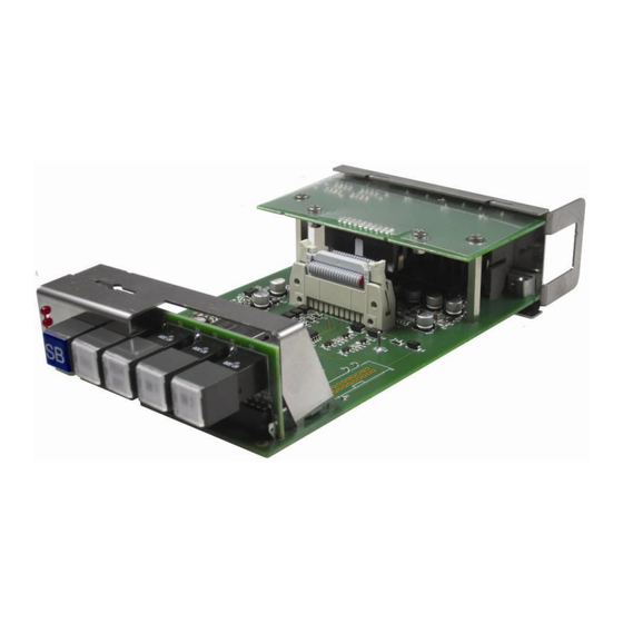
RUB SB
Monitoring and Changeover Module
for Analogue Video Sync Signals
Black Burst – Tri-Level – VITC
Monitor for Real-Time Synchronization
Functional Description and Specifications
Supplement to the "Installation & Systems Manual RUBIDIUM SERIES"
Version: 1.3
December 2, 2020
Advertisement
Table of Contents

Subscribe to Our Youtube Channel
Related Manuals for Plura Rubidium Series


Summary of Contents for Plura Rubidium Series
- Page 1 TIMING SOLUTIONS RUB SB Monitoring and Changeover Module for Analogue Video Sync Signals Black Burst – Tri-Level – VITC Monitor for Real-Time Synchronization Functional Description and Specifications Supplement to the “Installation & Systems Manual RUBIDIUM SERIES” Version: 1.3 December 2, 2020...
-
Page 3: Table Of Contents
Functional Description and Specifications RUB SB Page 3 CONTENTS REVISION HISTORY COPYRIGHT GENERAL REMARKS MODULE SB GENERAL DESCRIPTION REAR PANEL AND CONNECTIONS SPECIFICATIONS TYPICAL APPLICATION DIAGRAM SOFTWARE UPDATE ELECTRONIC PART EXCHANGE OPERATING DESCRIPTION FUNCTIONAL OVERVIEW 2.1.1 Basic Functions 2.1.2 Overview of Error Indications and Alarms in General 2.1.3 Overview of Error Indications at the Status Monitor 2.1.4... - Page 4 STATUS OF THE REAL-TIME REFERENCE STATUS OF FAN AND POWER SUPPLIES THE RUBIDIUM CONFIGURATION TOOLS THE RUBIDIUM CONFIGURATION PC PROGRAM THE RUBIDIUM SERIES HTTP SERVER “FUNCTIONS“ “KEYS“: KEYS AND LAMPS, LEDS AND GPOS “SWITCHER“: SET-UP OF GENERAL PARAMETERS “VIDEO“: SET-UP OF VIDEO AND VITC MONITORING “LINK”: COMMUNICATION BETWEEN MODULES...
-
Page 5: A1 Revision History
Subject Preliminary documents, changes without notice. May 7, 2013 First released document. September 3, 2019 Changed address of Plura Europe GmbH. November 4, 2019 Fixed NMEA baud rate to 4800. November 30, 2020 Re-formatted in new design. Due to constant product development the features of this module are subject to change. The current functional description always refers to the current software and the current configuration tool. -
Page 6: A2 Copyright
A3 General Remarks This manual is a supplement to the ‘Installation & Systems Manual RUBIDIUM SERIES’. Please read the below listed chapters of the ‘Installation & Systems Manual RUBIDIUM SERIES’, as these chapters are necessary for the safe and proper use of RUB modules: •... -
Page 7: Module Sb
Functional Description and Specifications RUB SB Page 7 Module SB 1.1 General Description This module can compare and contrast two sources of analogue video sync signals for differences and real-time behaviour. Each source may consist of one or two signals, black burst or tri-level, even mixed. -
Page 8: Rear Panel And Connections
Page 8 Functional Description and Specifications RUB SB 1.2 Rear Panel and Connections REF IN REF OUT 8 ..1 8 ..1 1 ..8 1 ..8 REF OUT VIDEO IN 1 VIDEO OUT... - Page 9 Functional Description and Specifications RUB SB Page 9 Signal descriptions Signal ground. VIDEO IN 1 Analogue video signal inputs, black burst or tri-level. VIDEO IN 2 VIDEO OUT Analogue video signal outputs, switched via relay to the corresponding video input (A or B). Video outputs should be terminated in 75 Ω.
-
Page 10: Specifications
Page 10 Functional Description and Specifications RUB SB 1.3 Specifications Video inputs Connector BNC (IEC169-8), 75 Minimum Nominal Maximum Signal level Bi-level sync amplitude from synchronizing to blanking level 0.14 V 0.30 V 0.61 V Tri-level sync amplitude from negative to positive peak 0.28 V 0.60 V 1.22 V... - Page 11 Functional Description and Specifications RUB SB Page 11 10 MHz In Connector RJ45 REF IN, pin 6 Termination Default = 75 Ω, could be altered to 50 Ω as an option DC offset ≤ ± 2.5 V Frequency range 0 – 33 MHz Amplitude sinusoidal, 0.6 –...
- Page 12 Page 12 Functional Description and Specifications RUB SB VCC24G_OUT Output of the DC Reversible fused. A continuous current of up to 120 mA can be ap- power supply of this plied over the whole specified operating temperature range. At an module, 23.8 VDC ambient temperature of e.g.
-
Page 13: Typical Application Diagram
Functional Description and Specifications RUB SB Page 13 1.4 Typical Application Diagram Redundant Video Sync System 10 MHz 10 MHz REF = 2 x Black Burst Time & Date + PPS Primary 2 x 10 MHz + 10 MHz Black Burst Black Burst REF = 2 x 10 MHz... -
Page 14: Software Update
Page 14 Functional Description and Specifications RUB SB 1.5 Software Update Software updates require a (windows operating system) computer and the “RUBIDIUM CONFIGURATION“ program. You can download the latest version of the program from: https://www.plurainc.com. Please check the PC connector at your RUBIDIUM housing: There is an USB or RS232 (with a DSUB9 connector) interface installed. -
Page 15: Electronic Part Exchange
Keyboard 1. Arrangement: Contact your local dealer or Plura to order the main electronic board and the keyboard for a replacement. It is essential that you have as much information ready as possible: Serial number of the module, software version number, set-up and configuration. This will help to ensure that you are getting a direct replacement, even regarding the set-up values –... -
Page 16: Operating Description
PC programs are available for free: Configuration of the module = RubidiumConfig.exe, status monitor = RubStatSE.exe. The RUBIDIUM SERIES HTTP server, located in the Ethernet module (RUB IE or RUB PM) enables the configuration of the module and offers a status monitor as well. -
Page 17: Overview Of Error Indications And Alarms In General
Functional Description and Specifications RUB SB Page 17 2.1.2 Overview of Error Indications and Alarms in General This module detects errors on video and VITC signals, on signals of the real-time reference, or on the module itself after a self-test. Basically, each individual error will be represented by a status, an error counter, and an indication of a failure. -
Page 18: Overview Of Error Indications At The Status Monitor
Page 18 Functional Description and Specifications RUB SB 2.1.3 Overview of Error Indications at the Status Monitor The System page of the status monitor shows the “overall failures” counter, the “overall errors” counter, and the individual errors of the system: The Video A page shows individual errors with respect to video signals at IN1 A and IN2 A. -
Page 19: Error Reset
Functional Description and Specifications RUB SB Page 19 2.1.4 Error Reset The following error indications and alarms are self-resettable (reset, if no errors are present): • The individual status bits at the status monitor. • GPO programmed as Signal 1 Failure, Signal 2 Failure, Signal 1 Warning, Signal 2 Warning. -
Page 20: Video Monitoring
Page 20 Functional Description and Specifications RUB SB 2.2 Video Monitoring This module monitors 2 x 2 video signals. Signals at input A (IN1 A, IN2 A) are checked and compared with each other, same way signals at input B (IN1 B, IN2 B) are checked and compared with each other. Comparing signals requires the same video format of these signals: IN1 A and IN2 A must have the same format;... -
Page 21: Measurements And Error Detections Comparing Signals In1 With In2
Functional Description and Specifications RUB SB Page 21 2.2.2 Measurements and Error Detections Comparing Signals IN1 with IN2 video detected = ‘yes’, if once a valid video signal at either input has been detected. This is a precondition for a possible changeover event. Phase difference and drift between video signals at IN1 and IN2: video1 –... -
Page 22: Measurements And Error Detections On Each Video Signal
Page 22 Functional Description and Specifications RUB SB 2.2.3 Measurements and Error Detections on each Video Signal format The video format will be detected automatically. All valid formats are shown at chapter ‘Specifications’. Colour sequence: Some video formats include a white pulse which identifies the colour field 1. cf ident pulse indicates that this pulse is present. - Page 23 Functional Description and Specifications RUB SB Page 23 video/pps drift Drift of the video signal against the PPS, i.e. the variation of phase difference in time. This is measured in 1/10 fields for interlaced formats, and in 1/10 frames for progressive formats.
-
Page 24: Consequences Of Errors
Page 24 Functional Description and Specifications RUB SB 2.2.4 Consequences of Errors Errors can be divided into the following groups: Error resulting from comparing two video signals (IN1 A with IN2 A, IN1 B with IN2 B): ‘video1 – video2 phase difference’... - Page 25 Functional Description and Specifications RUB SB Page 25 This table shows all the individual errors and their consequences: Individual Errors Major Errors Minor Errors status yes yes yes yes yes yes Sets bit to 1 counts yes yes yes yes yes yes yes Counts + 1 overall errors...
-
Page 26: Vitc Monitoring
Page 26 Functional Description and Specifications RUB SB 2.3 VITC Monitoring PAL 625/50 or NTSC 525/59.94 video signals can have a VITC time code embedded. This time code will be read and checked. VITC signals at input A (IN1 A, IN2 A) are checked and compared with each other, same way VITC signals at input B (IN1 B, IN2 B) are checked and compared with each other. -
Page 27: Measurements And Error Detections On Each Vitc Signal
Functional Description and Specifications RUB SB Page 27 2.3.2 Measurements and Error Detections on each VITC Signal frame rate The displayed frame rate corresponds to the picture rate of the video signal and can be 24, 25, 30, or 30 drop. time Time address of the VITC word. - Page 28 Page 28 Functional Description and Specifications RUB SB an error, the comparison of these two times can be programmed (please refer to chapter ‘”Switcher”: Set-Up of General Parameters’ → set-up of the ‘Reference Compare’ parameter). vitc/ref difference max Maximum value of time difference measured since power has turned on, or since last error reset.
-
Page 29: Consequences Of Vitc Errors
Functional Description and Specifications RUB SB Page 29 2.3.3 Consequences of VITC Errors Errors can be divided into the following four groups: Error resulting from comparing two VITC signals (IN1 A with IN2 A, IN1 B with IN2 B): ‘vitc1 – vitc2 difference’. - Page 30 Page 30 Functional Description and Specifications RUB SB This table shows all the individual errors and their consequences: Individual Errors Major Errors Minor Errors status yes yes yes yes yes yes yes yes Sets bit to 1 counts yes yes yes yes yes yes yes yes yes Counts + 1...
-
Page 31: Video/Vitc Changeover
Functional Description and Specifications RUB SB Page 31 2.4 Video/VITC Changeover SB monitors video and VITC of two sources. Each source can deliver two signals (A, B). IN A1 'Primary' Changeover With the default set-up (‘Factory Settings’), the Source OUT A module operates in the automatic mode, i.e. -
Page 32: Real-Time Reference Monitoring
‘The Epoch Method’). This measurement requires a data protocol which includes time, date, and the amount of leap seconds. Plura RUB modules GPS 10 MHz and GLS 10 MHz send this protocol if ‘Meinberg GPS’ has been selected. -
Page 33: Measurements And Error Detections
Functional Description and Specifications RUB SB Page 33 • ‘last event’: Time of last manual or automatic changeover, or time of last error reset. • Time of an entry to the log file of an Ethernet module – this requires enabling the ‘Reference Telegram’... - Page 34 Page 34 Functional Description and Specifications RUB SB Drift between 10 MHz and PPS: Any faultless real-time synchronization requires that there is no drift between the 10 MHz signal and the PPS signal – apart from a warm-up period. pps/10 MHz drift valid ‘valid’...
-
Page 35: Consequences Of Real-Time Reference Errors
Functional Description and Specifications RUB SB Page 35 2.5.3 Consequences of Real-Time Reference Errors Each error has the following consequences: • Indication of an error at the status monitor (‘status’ = 1). • Error counter counts one up (maximum value of ‘counts’ = 65,535). •... -
Page 36: Self-Test
Page 36 Functional Description and Specifications RUB SB 2.6 Self-Test Apart from checking the video and VITC signals and the signals of the real-time reference, the module performs a self-test. The following errors will be indicated at the System page of the status monitor: Chapter ‘Overview of Error Indications at the Status Monitor’... - Page 37 Functional Description and Specifications RUB SB Page 37 This table shows all the individual errors and their consequences: power on relay status sets bit to 1 counts counts + 1 overall errors counts + 1 fail sets bit to 1 yes* yes* overall failures...
-
Page 38: Alarms
Page 38 Functional Description and Specifications RUB SB 2.7 Alarms 2.7.1 Overview and Suggestions for Installation In order to get aware of a problem, the module could periodically be checked (status monitor, LEDs, lamps, log file of the Ethernet module), or the module could be integrated into a management and control system via GPO and/or SNMP. -
Page 39: Alarms By Gpo Outputs
Functional Description and Specifications RUB SB Page 39 2.7.2 Alarms by GPO Outputs The module has four GPOs (General Purpose Outputs). Basically, the functions of these outputs are programmable utilizing the Keys function of one of the configuration tools. (→ Chapter ‘The Rubidium Configuration Tools’ → ‘”Keys”: Keys and Lamps, LEDs and GPOs’) The following functions for the GPOs are provided to indicate errors and failures: Signal 1 Failure Recommended GPO: GPO_1... -
Page 40: Alarms By Snmp Traps
Page 40 Functional Description and Specifications RUB SB 2.7.3 Alarms by SNMP Traps SNMP functionality for a RUBIDIUM system requires the installation of an Ethernet module (RUB IE or RUB PM) with option S (SNMP). Utilizing one of the configuration tools, the SNMP traps can be enabled and disabled at the System page (please refer to chapter ‘”System”: Identification, Reset, SNMP, Fan Control’). -
Page 41: Entries In The Log File Of An Ethernet Module
Functional Description and Specifications RUB SB Page 41 2.7.4 Entries in the Log File of an Ethernet Module The use of the log file requires the installation of an Ethernet module (RUB IE or RUB PM). As it is shown in the tables of chapters: •... -
Page 42: Status Monitor
Status Monitor 3.1 Status Monitor by the Ethernet Module The RUBIDIUM SERIES HTTP server, which is located in the Ethernet module (RUB IE or RUB PM), offers a status monitor. Please refer to the ‘Functional Descriptions and Specifications RUB Ethernet’ manual for a detailed description of how to access the RUBIDIUM SERIES system and how to open the RUBIDIUM homepage. -
Page 43: Status Monitor By A Pc Program
Page 43 3.2 Status Monitor by a PC Program The PC program RubStatSE.exe uses the PC interface (RS232 or USB) of the RUBIDIUM housing. This program is part of the “Rubidium Series, config software” packet you can download at: https://www.plurainc.com. -
Page 44: Status 'System
Page 44 Functional Description and Specifications RUB SB 3.3 Status ‘System’ The System page of the status monitor gives a feedback on all relevant operational parameters and on the general operating mode. System Set-up Reflects the set-up as selected by a configuration tool. Please refer to chapter ‘”Switcher”: Set-Up of General Parameters’... - Page 45 Functional Description and Specifications RUB SB Page 45 System Tally Reflects the state of the latching relays, the GPOs, the lamps and the LEDs. The GPOs, lamps and LEDs have programmable functions. For service purpose, ‘System Tally’ reflects the state of the default function, independent of what has been really assigned to.
-
Page 46: Status 'Video A' And 'Video B
Page 46 Functional Description and Specifications RUB SB 3.4 Status ‘Video A’ and ‘Video B’ The Video A page of the status monitor shows measurements and errors regarding signals VIDEO IN 1 A and VIDEO IN 2 A. The Video B page of the status monitor shows measurements and errors regarding signals VIDEO IN 1 B and VIDEO IN 2 B. - Page 47 Functional Description and Specifications RUB SB Page 47 Video 1 – Video 2: Monitoring signal pairs (IN1A – IN2A and IN1B – IN2B). video detected ‘yes’, if at least one signal of a pair has been detected. video1 – video2 phase difference Phase difference between both video signals.
-
Page 48: Status 'Vitc A' And 'Vitc B
Page 48 Functional Description and Specifications RUB SB 3.5 Status ‘VITC A’ and ‘VITC B’ The VITC A page of the status monitor shows measurements and errors regarding VITC signals at VIDEO IN 1 A and VIDEO IN 2 A. The VITC B page of the status monitor shows measurements and errors regarding VITC signals at VIDEO IN 1 B and VIDEO IN 2 B. - Page 49 Functional Description and Specifications RUB SB Page 49 VITC 1 – VITC 2: Comparing VITC of signal pairs (IN1A – IN2A and IN1B – IN2B). vitc detected ‘yes’, if at least one VITC signal of a pair has been detected. vitc1 –...
-
Page 50: Status Of The Real-Time Reference
Page 50 Functional Description and Specifications RUB SB 3.6 Status of the Real-Time Reference SB monitors the pulse-per-second input signal (PPS), the serial data string with time & date and status information (RXD), and the correct timing of both signals with respect to a definite correspondence of the serial data to the PPS signal. - Page 51 Functional Description and Specifications RUB SB Page 51 seconds, this counter will count upwards. Next measurement will take place when this counter reaches 1000 and then resets to zero. limit reference sync loss error Display of the limiting value regarding loss of synchronization. This limit can be set in the range of 1 –...
-
Page 52: Status Of Fan And Power Supplies
SB – as all configurable RUBIDIUM modules – is able to monitor the fan and power supplies which are plugged to the same housing as SB. Please refer to the document ‘Installation & Systems Manual RUBIDIUM SERIES’ for a detailed description. -
Page 53: The Rubidium Configuration Tools
PC’s keyboard afterwards. 4.2 The Rubidium Series HTTP Server The RUBIDIUM SERIES HTTP server is located in the Ethernet module (RUB IE or RUB PM). A 10/100Base-T Ethernet connection and a web browser allow access to the RUBIDIUM system. -
Page 54: Functions
Store and Load Configurations on the Module (*) System Identification, Reset, SNMP, Fan Control Keys Keys and Lamps, LEDs and GPOs Switcher Set-Up of General Parameters Video Set-Up of Video and VITC Monitoring Link Communication between Modules (*) refer to “Installation & Systems Manual RUBIDIUM SERIES”... -
Page 55: Keys": Keys And Lamps, Leds And Gpos
(keys and lamps) and four LEDs (Light Emitting Diodes). Basically, the functions of these in- and outputs are programmable. Some functions presented by the configuration tool maybe assigned to special options, and therefore are not applicable with the standard firmware. For further information please contact Plura OPER PRIM FAIL... - Page 56 Page 56 Functional Description and Specifications RUB SB The following functions for the keys are provided for this module: Recommended Function Description Clear Resets all error counters. F1: FAIL Reset All Resets all error counters and status. F1: FAIL Changeover Manual changeover to VIDEO IN 1 (‘primary’...
- Page 57 Functional Description and Specifications RUB SB Page 57 The following functions for the GPOs are provided for this module: Function Description Recommended Signal 1 Failure Indicates a failure at VIDEO IN 1: GPO_1 any major video or VITC error. Signal 2 Failure Indicates a failure at VIDEO IN 2: GPO_2 any major video or VITC error.
-
Page 58: Switcher": Set-Up Of General Parameters
Page 58 Functional Description and Specifications RUB SB 4.5 “Switcher“: Set-Up of General Parameters These set-ups are provided for the monitoring and changeover characteristics. Configuration (example shows a screen shot of the PC program tab): System Alarm Disable SB monitors some system characteristics. For a detailed description of each item please refer to chapter ‘Self-Test’. - Page 59 Functional Description and Specifications RUB SB Page 59 System Select the operating mode and some parameters (default values in bold characters): Item Selection Description Changeover Automatic Automatic or manual changeover operating mode. Manual → Chapter “Video/VITC Changeover”. Reference Meinberg Std ... SB expects a PPS and a serial data string from a real-time NMEA $GPRMC...
-
Page 60: Video": Set-Up Of Video And Vitc Monitoring
Page 60 Functional Description and Specifications RUB SB 4.6 “Video“: Set-Up of Video and VITC Monitoring This function offers to set up the video and VITC monitoring and changeover characteristic. Configuration (example shows a screen shot of the PC program tab): Set-up can be done independent for input A... - Page 61 Functional Description and Specifications RUB SB Page 61 Selecting the limiting values: Item Selection Description Limit Phase difference between two video signals: 1 – 20 Video/Video (10) ‘video1 – video2 phase difference’ error will be indicated if the Phase phase difference equals or exceeds this limit. [ms] →...
-
Page 62: Link": Communication Between Modules
Page 62 Functional Description and Specifications RUB SB 4.7 “Link”: Communication between Modules Link uses the Rubidium internal TC_link interface to transmit or receive data. This interface is shared by all the modules in one frame, and via the RLC connector it is possible to link further modules at different frames. -
Page 63: System": Identification, Reset, Snmp, Fan Control
Functional Description and Specifications RUB SB Page 63 4.8 “System“: Identification, Reset, SNMP, Fan Control Configuration (example shows a screen shot of the PC program tab): Unit Name: The connected module can get a name. You may enter, change, or verify this name at this window. - Page 64 Contact Us U.S.A. Corporate Offices: Plura Broadcast, Inc. Ph: +1-602-944-1044 Sales@plurainc.com GERMANY Plura Europe GmbH Ph: +49-6725-918006-70 Sales@plurainc.com Plura MEA U.A.E. Ph: +971-50-715-9625 Sales@plurainc.com S. KOREA Plura Asia Ph: +82-10-6688-8826 Sales@plurainc.com...
Need help?
Do you have a question about the Rubidium Series and is the answer not in the manual?
Questions and answers