Table of Contents
Advertisement
Advertisement
Table of Contents

Related Manuals for FORST TR8D


Summary of Contents for FORST TR8D
- Page 1 Operation & Maintenance Manual English 12-M-001 Revision 1.1...
- Page 2 Redwood Global Ltd, Unit 86, Livingstone Road, Walworth Business Park, Andover, Hampshire. SP10 5NS. United Kingdom Page 2...
-
Page 3: Table Of Contents
Contents 1.0 Introduction ....................... 5 1.1 Purpose of Chipper ....................6 1.2 Exterior Components .................... 7 2.0 Safety ........................9 2.1 Safety Working...................... 9 2.2 DO’s and DON’Ts ....................10 2.3 Noise Test Information ..................11 3.0 Transportation & Storage ..................12 3.1 Track control and driving .................. - Page 4 5.6.1 Removal and Replacement ................. 30 5.9 Oils, Fluids and Lubricants ................. 31 5.10 Drive belt tension ....................32 5.11 Battery ....................... 33 5.11.1 Battery safety information................33 5.11.2 Storage and transport ................33 5.11.3 Initial operation ..................33 5.11.4 Battery removal & maintenance ..............33 5.11.5 Charging.....................
-
Page 5: Introduction
1.0 Introduction Thank you for becoming the owner of this Redwood Global Ltd, Först TR8D wood chipping machine. By observing the contents of this manual, we hope the chipper gives safe and productive service. This user manual is intended for the owner/operator to safely and effectively operate this chipper and carry out routine maintenance between services. -
Page 6: Purpose Of Chipper
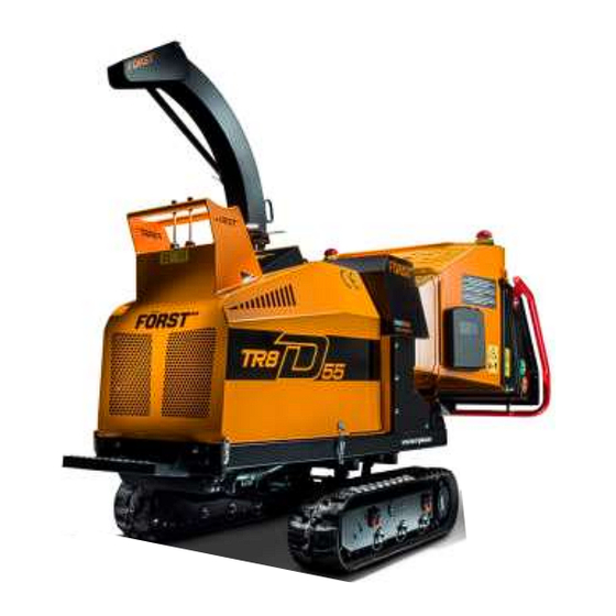
1.1 Purpose of Chipper The Först TR8D is designed to reduce wood material up to 203mm diameter and 254mm wide to woodchip. This chipper is capable of processing up to 5.5 tonnes of wood per hour. Page 6... -
Page 7: Exterior Components
1.2 Exterior Components 1. E-Stop 10. Track base 2. Hopper tray latch 11. Engine cover 3. Stop bar 12. Footplate 4. Feed touch sensors 13. Throttle 5. Control valve speed adjust 14. Control levers 6. Fuel tank 15. Lifting point 7. - Page 8 1. Engine cover latch 6. Hopper tray 2. Document holder 7. E-Stop 3. Battery 8. Safety curtain 4. Removable hopper 9. Chute handle 5. Feed touch sensors 10. Chute Page 8...
-
Page 9: Safety
2.0 Safety 2.1 Safety Working Before using this chipper, make sure that you are trained and fluent in its operation. Know the location of and how to use all the safety features. Know how to control the feed and stop the chipper in an emergency. Be familiar with the hazards and safe working practices to prevent injury and damage to property and chipper. -
Page 10: Do's And Don'ts
2.2 DO’s and DON’Ts • DO ensure that the starting of the chipper can cause • DO NOT use chipper in poor visibility or insufficient no hazard before starting. i.e. no persons are in the light to see clearly • DO NOT use or attempt to start the chipper without the hopper or in any other danger aera •... -
Page 11: Noise Test Information
2.3 Noise Test Information Chipper TR8D 55 Test 50mm x 50mm 4.2m long sawn pine Noise levels above 85dB (A) will be experienced at the working position and within a 4-metre radius. Operators and personnel within a 4-metre radius must wear appropriate ear protection at all times while chipper is in operation to prevent the risk of hearing damage. -
Page 12: Transportation & Storage
3.0 Transportation & Storage 3.1 Track control and driving 1. Left track forward & reverse 2. Varitrack (optional): • Forward – tracks out • Backward – tracks in 3. Right track forward & reverse Driving controls are all situated on the engine cover and operated while at the machine front or standing on the fold down foot plate. -
Page 13: Transporting The Chipper
3.2 Transporting the Chipper • Always carryout loading to and unloading • Drive slowly while loading/unloading and from the transporting vehicle on solid take care when the machine passes over level ground. hump at the ramp to bed join. • Use a loading ramp of less than 15° that •... -
Page 14: Lifting The Chipper
3.4 Lifting the Chipper The lifting eye is designed for securely holding the chipper’s weight only. Do not use hoist hook directly on the lifting eye. Use a correctly rated safety shackle. Inspect lifting eye before each use and do not use if damaged. 3.5 Storage of the Chipper For safe storage of the chipper, ensure the following points are met: 1. -
Page 15: Chipper Operation
4.0 Chipper Operation 1. Fold down hopper tray 2. Start engine a. Turn ignition key to pre-heat b. Wait for display to indicate ‘start engine’ c. Turn key to crank engine and release once firing 3. Allow engine to run for 30 seconds at idle, then increase revs to full 4. -
Page 16: Control Panel & Ignition
4.1 Control Panel & Ignition This chipper is fitted with an engine PLC (Programmable Logic Controller) system that manages the engine, feed and all safety features. The control panel is located on the right-side panel. Feed and engine speed are controlled with a “No Stress” function ensuring that cutting conditions are kept within optimum limits. -
Page 17: Ignition Switch
4.1.2 Ignition Switch 1. Key rotation in switch to start 2. Ignition switch positions & function 3. Off 4. Ignition 5. Pre-Heat 6. Spring biased to pre-heat when released 7. Start 8. Key rotation in switch to stop Turn ignition key clockwise to first position, then to pre-heat, start display will show, enables pre-heat automatically showing start display + pre-heat. - Page 18 P2 shows I/O tests. Tests all functions and safety controls. Pin screen P3 shows No-Stress Settings • Actual RPM • Upper Band - 1400 RPM • Mid Band – 1125 RPM • Lower Band – 925 RPM • Pin screen automatically displays if any setting changes are attempted. To stop engine, turn off with ignition key by turning fully anti-clockwise.
-
Page 19: Feed Speed Adjustment
4.2 Feed Speed Adjustment Control valve speed adjustment Position indicated by pip 0 = minimum 10 = maximum The feed speed can be adjusted to suit the material being chipped. Turn dial to align number with pip. Set feed speed so that the No-Stress operates as little as possible, this will give the highest throughput. -
Page 20: Emergency Stopping
4.3 Emergency Stopping 1. Red Stop Bar 2. Orange reverse button 3. Green forward button 4. E-Stop Before using the chipper: 1. Start the machine with the ignition key on the control panel. 2. With the engine running at full speed tap the green button (3) and the rollers will go into forward (chipping mode). -
Page 21: Feed Jam & Blockages
4.4 Feed Jam & Blockages Be aware that whatever is fed into the machine has to come out of the chute. Always monitor the state of chip flow out of the chute. If it stops, STOP FEEDING MATERIAL IMMEDIATELY. Continuing to feed material will further compact a blockage and make it more difficult to clear. -
Page 22: Routine Maintenance
5.0 Routine Maintenance The following must be checked at least on a daily basis during use (also see Service schedule): • Check engine oil • Check water level in radiator • Check debris screen on front of radiator and remove any debris •... -
Page 23: Debris Screen
5.1 Debris Screen 1. Remove the 6 x M8 nuts & bolts and remove the screen 2. Brush off any debris from both sides of the screen 3. Brush off any debris from the radiator 4. Replace screen with 6 x M8 nuts & bolts 5.2 Engine Maintenance Please refer to the engine manual supplied with this machine for the following: •... -
Page 24: Service Schedule
5.4 Service Schedule Engine Chipper Tighten hydraulic ● fittings Check engine oil ● level & top up if Check fasteners necessary Visual check for ● fluid leaks ● Check drive belts Grease via central ● point on control panel Change hydraulic ●... - Page 25 Service Schedule continued Engine Chipper Check & recharge ● battery Change feed roller Replace fuel filter ● bearings on motor cartridge side ● Clean out fuel tank ● Clean radiator Replace engine fan ● belt Check & recharge Change hydraulic ●...
-
Page 26: Chipper Diagrams
5.5 Chipper Diagrams 5.5.1 Main Covers • Opening sequence: ‘A’ then ‘B’ then ‘C’ 1. Engine cover latch (x2) 2. Chipping chamber cover bolts (x2 M12) 5.5.2 Side Panel 1. Side panel 3. Hydraulic oil filter 2. 6 x Fasteners 4. -
Page 27: Top Feed Roller
5.5.3 Top Feed Roller 1. Top feed roller M12 securing 3. Side panels screw hole 4. Top feed roller lifting tool socket 2. Chipping chamber cover fixing bolts 5.5.4 Engine Bay 1. Radiator 5. Alternator 2. Hydraulic Pump 6. Oil filter 3. -
Page 28: Blade Changing
5.6 Blade Changing WARNING – Rigger Gloves must be worn whilst changing the blades WARNING – It is essential that only genuine parts are used guaranteeing the correct grade of Blade, bolt, washer and nut 1. Turn off chipper and remove the ignition keys 2. -
Page 29: Blade Sharpening
5.7 Blade Sharpening For optimum performance, blades need to be kept sharp. Minimum safe blade size after sharpening is shown below. Also markon the blade. After sharpening, the blade gap must be re-set by using a blade shim. Shims are available in thicknesses of 0.5, 1, 1.5, 2 &... -
Page 30: Hydraulic Oil Filter
5.8 Hydraulic Oil Filter Use protective plastic gloves to keep oil off skin, dispose of oil and filter in an environmentally responsible manner. Item Description Complete Filter Filter Element Seal Kits O-ring for filter element O-ring for housing Anti-extrusion ring Gasket O-ring Protection seal... -
Page 31: Oils, Fluids And Lubricants
5.9 Oils, Fluids and Lubricants Engine Oil: HD SAE 10w40 E9 Please consult your Doosan engine operator’s manual for oil quantities relating to your engine type. Hydraulic Oil: ISO VG 46. It is advised that the oil is checked and topped up to the RED LINE on the sight glass, when the machine is cold and on a level surface. -
Page 32: Drive Belt Tension
5.10 Drive belt tension The flywheel V belts must be checked for tension and condition. If any belt shows signs of wear, surface damage, shredding, excessive glazing, or have been stretched to their limit, they must be replaced. Multiple belt drives must have all belts replaced at the same time. -
Page 33: Battery
5.11 Battery 5.11.1 Battery safety information 1. Battery acid is highly corrosive. For safety reasons, wear eye protection when handling a battery. Do not tilt battery as acid could escape from vents. 2. Keep children away from acid and batteries. 3. -
Page 34: Charging
7. Remove battery. Clean with a moist anti-static cloth to avoid electrostatic discharge and explosion risk. Charge and check electrolyte level if appropriate. 8. Clean out battery tray. Apply a thin film of petroleum jelly to terminals to prevent corrosion. 9. -
Page 35: Taking Battery Out Of Service
Connect in the sequence of 1 – 2 – 3 – 4 as shown and as follows: Connect one end of the red jump lead to the machine battery positive (+) terminal. 4. Connect the other end of the red jump lead to the support vehicle battery positive (+) terminal. -
Page 36: Parts Lists & Diagrams
6.0 Parts Lists & Diagrams 6.1 Tray & Stop Bar Item Part No Description Item Part No Description 12-03-083 Cable cover 12-14-013 M8 washer ISO 7089 12-03-104 Trip mech guard fab assy 12-14-014 M8 Spring washer DIN 128 12-05-050 Security Nut 12-14-017 M6 washer ISO 7089 12-10-071 Inductive proximity sensor kit 12-14-020 M4 Washer... -
Page 37: Chipping Chamber
6.2 Chipping Chamber Item Part No Description Item Part No Description 14-A-036 Flywheel Assy 12-14-006.1 M16 Serrated Washer 12-10-305 B75 1940 Belt 14-03-126 Washer Plate 12-10-071 Inductive proximity sensor kit 12-24-003 Oil level glass 12-10-131 Brass vent screw 1/4in BSPP 12-10-015 Hydraulic oil filler cap - plastic 12-10-071 Inductive proximity sensor kit... -
Page 38: Top Feed Roller Assembly
6.3 Top feed roller assembly Page 38... -
Page 39: Flywheel Assembly
6.4 Flywheel Assembly Page 39... -
Page 40: Bottom Feed Roller
6.5 Bottom Feed Roller Page 40... -
Page 41: Anvil
6.6 Anvil Page 41... -
Page 42: Stone Trap
6.7 Stone Trap Item No Part No Description Quantity 12-12-504 M10 x 20Lg 8.8 Hex Head screw 2 12-14-010 M10 Spring Washer DIN 128 12-14-009 M10 Washer ISO 7089 14-03-024 Feed roller cover Page 42... -
Page 43: Flywheel Belt Tensioner Assembly
6.8 Flywheel belt tensioner assembly Item No Part No Description Quantity 12-12-1104 M16 x 110Lg 8.8 Hex Head bolt 12-14-019 M16 Spring washer DIN 128 12-14-005 M16 Washer ISO 7089 12-11-011 6304 2RS Deep groove ball bearing 52 OD, 20 ID, 15 wide 12-01-036 Flat idler pulley-2x 17 V belt 12-01-024 Flat idler pulley shaft-2x 17 V belt 12-13-005 M16 nyloc nut ISO 7040... -
Page 44: Safety Curtain
6.9 Safety Curtain Item No Part No Description Quantity 14-05-008 Safety curtain 14-05-007 Curtain clamp 12-14-013 M8 washer ISO 7089 12-14-014 M8 Spring washer DIN 128 12-12-401 M8 x 25 Lg 8.8 Hex Head screw 4 Page 44... -
Page 45: Chute Assembly
12-13-003 M12 nyloc nut ISO 7040 12-01-043 Hood hinge stud 12-19-051 Chute hood fab assy 12-30-024 Forst small orange decal 12-15-020 M12 Elastomer washer OD 25-ID 12 x 5 THK 12-19-055 Chute handle - standard 12-10-004 M12 female steel handle... -
Page 46: Fuel Tank Assembly
6.11 Fuel tank assembly Item No Part No Description Quantity 12-10-150 Fuel tank cap 12-10-151 Lockable fuel cap (optional) 12-10-152 Fuel tank filter 12-02-001 Fuel tank 35L moulded assy 12-10-154 Fuel tank 5mm connector 12-10-153 Fuel tank 5mm grommet 12-14-008 M12 Bonded washer (Dowty) 2 12-10-027 Banjo M12 12-10-026 Banjo bolt M12 Page 46... -
Page 47: Hydraulics Circuit Diagram
6.12 Hydraulics circuit diagram 1. Feed roller motors 5. Control valve 2. Track motors 6. Return Line Filter 3. Track width cylinders 7. Oil tank (optional) 8. Tandem hydraulic 4. Test points pump 11cc/rev 9. Engine Page 47... -
Page 48: Electrical Circuit Diagrams
6.13 Electrical Circuit Diagrams 6.13.1 Touch Sensors 6.13.2 Wiring Harness Page 48... -
Page 49: Decals
6.14 Decals Decal meaning: 1. CE (Conformité Européenne or European Conformity) mark. Manufacturer’s declaration that the product complies with the essential requirements of the relevant European health, safety and environment protection legislation 2. Ignition switch stop 3. Hearing and eye protection of an appropriate specification to be worn 4. -
Page 50: Manufacturer's Statutory Plate
6.15 Manufacturer’s Statutory Plate Information on the Manufacturer’s plate in line order from top to bottom is as follows: 1. Manufacturing company & address 2. Serial Number 3. Machine designation 4. Mass 5. Power of prime mover 6. Year of construction 7. -
Page 51: Warranty And Certification
7.0 Warranty and Certification 7.1 Warranty 7.1.1 Warranty Statement 1. Redwood Global Ltd guarantee all Först equipment supplied by them against any defect in manufacture and assembly – this guarantee is for a period of 12 months commencing on the date of sale to the first end user. 2. -
Page 52: Certification
7.2 Certification CERTIFICATE & DECLARATION OF CONFORMITY FOR CE MARKING Company contact details: Redwood Global Ltd, Unit 86, Livingstone Road, Walworth Business Park, Andover, Hampshire. SP10 5NS. United Kingdom Redwood Global Ltd declares that their: Wood Chippers listed as the following models TT6 Towed ST6 Towed &...
Need help?
Do you have a question about the TR8D and is the answer not in the manual?
Questions and answers