
Related Manuals for FORST TR6


Summary of Contents for FORST TR6
- Page 1 Woodchipper USER MANUAL ENGLISH 21/11/2018 Revision10 Redwood Global Ltd, Unit 86, Livingstone Road, Walworth Business Park, Andover, Hampshire. SP10 5NS. United Kingdom...
-
Page 2: Table Of Contents
P a g e Table of Contents Introduction ............................Purpose of machine ..........................Exterior component identification ....................... Tiltbed machine ..........................7 Safety ..............................8 Safe working ............................. 8 Machine lifting ........................... 9 DOs and DON’Ts ........................... 10 Noise test information ........................Machine operation ................ - Page 3 P a g e Hydraulic oil filter ..........................32 Drive belt tension ..........................Battery ..............................Battery safety information ......................34 Storage and transport ........................Initial operation ..........................34 Battery removal & maintenance ....................Charging ............................35 Jump starting........................... 35 Taking battery out of service ......................36 Parts lists .............................
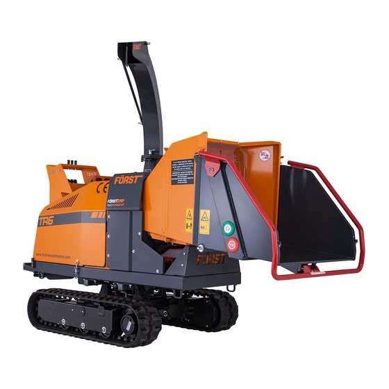
- Page 4 This manual must remain with the machine for reference by operators and includes hiring or if the machine is resold. Purpose of machine The Forst TR6 is designed to reduce wood material up to 150mm diameter to woodchip. This machine is capable of processing up to 5 tonnes of wood per hour.
- Page 5 P a g e...
- Page 6 P a g e Exterior component identification Figure 1 TRIP BAR CONTROL VALVE FEED SPEED ADJUSTMENT HOPPER TRAY LATCH REMOVABLE HOPPER CHIPPING CHAMBER COVER CHUTE HOOD CHUTE MACHINE LIFTING EYE MANUFACTURER'S STATUTORY PLATE ON CHIPPING CHAMBER COVER UNDER ENGINE COVER 10 SERIAL NUMBER ON CHIPPING CHAMBER UNDER ENGINE COVER 11 TRACK CONTROL LEVERS 12 THROTTLE...
- Page 7 P a g e 25 FEED START/STOP TOUCH SENSORS 26 HOPPER TRAY Figure 2 CHUTE HANDLE CHUTE HOOD LOCK HANDLE CHUTE ROTATION LOCK HANDLE SAFETY CURTAIN BATTERY REAR TRANSIT LASHING EYE...
-
Page 8: Safety
P a g e Tiltbed machine THROTTLE TILT LEVER TRACK WIDTH LEVER Figure 3 TRACK DIRECTION & SPEED CONTROL LEVERS Tilt lock pins TILT LOCKING PINS, TWO ON EACH SIDE FRONT TRANSIT LASHING EYE must only be released as a pair on one side at a time. Tilt will only work sideways. - Page 9 P a g e 3. In use, woodchip and debris are ejected with considerable force from the chute and can travel up to 10m. Make sure the chute directs woodchip to a safe location so that no one can be harmed or property damaged. Do not allow discharge to be directed onto roads or public rights of way.
-
Page 10: Machine Lifting
P a g e 14. Carefully site the machine so operators can work furthest from any local danger. For example, on a road side, place machine so operators work on the verge and not in the road exposed to traffic. Machine lifting The lifting eye is designed for securely holding the machine’s weight only. -
Page 11: Dos And Don'ts
P a g e | 10 DOs and DON’Ts DO NOT use or attempt to start the machine without the discharge chute or guards correctly and securely fitted. DO NOT stand directly in front of the in-feed hopper when using the chipper. Stand to one side. -
Page 12: Noise Test Information
P a g e | 11 Noise test information Machine Forst TR6 Notes Tested chipping 50 x 50mm sawn pine 4.2m in length. Noise levels above 85dB (A) will be experienced at the working position and within a 4 metre radius. Operators and personnel within a 4 metre radius must wear appropriate ear protection at all times while machine is in operation to prevent the risk of hearing damage. -
Page 13: Machine Operation
P a g e | 12 Machine operation STANDARD PROGRAMME ORANGE BUTTON MACHINE USE PROGRAMME MACHINE USE TOUCH SENSOR HOPPER TOUCH SENSOR HOPPER STAGE STAGE Fold down hopper tray Fold down hopper tray Start engine. Start engine. Turn ignition key to pre-heat Turn ignition key to pre-heat Wait for display to indicate"Start Wait for display to indicate"Start... -
Page 14: Machine Control Panel, Start/Stop & Operating Settings
P a g e | 13 Machine control panel, start/stop & operating settings This machine is fitted with an engine PLC (Programmable Logic Controller) system that manages the engine, feed and all safety features. The control panel is located on the right side panel (see Figure 1). Feed and engine speed are controlled with a “No Stress”... - Page 15 P a g e | 14 If engine fails to start, turn key to off position and start process again. P1 shows Working Hours and charging indicator text at the screen bottom centre. P2 shows I/O tests. Tests all functions and safety controls. Pin screen P3 shows No-Stress Settings Actual RPM...
-
Page 16: Feed Speed Adjustment
P a g e | 15 P4 shows Pre-Heat Settings To stop engine turn off with ignition key by turning fully Enable Pre-Heat – True anticlockwise. Pre-Heat Time – 10 Crank Time – 3 Feed speed adjustment Figure 6 The feed speed can be adjusted to suit the material being chipped see Figure 6. - Page 17 P a g e | 16 Push the RED SAFETY BAR. This will stop the feed rollers instantly. The chipper flywheel will still be turning. Turn the throttle lever to idle and switch off the engine with the ignition key. Red Stop Bar Red Stop Button Green Forward and Reverse Button...
-
Page 18: Emergency Stopping - Orange Button Program
P a g e | 17 Emergency Stopping – Orange Button Programme Push the RED SAFETY BAR. This will stop the feed rollers instantly. The chipper flywheel will still be turning. Turn the throttle lever to idle and switch off the engine with the ignition key. - Page 19 P a g e | 18 Always monitor the state of chip flow out of the chute. If this stops, STOP FEEDING MATERIAL IMMEDIATELY. Continuing to feed material will further compact a blockage and make it more difficult to clear. If the chipping chamber or chute become blocked: 1.
- Page 20 P a g e | 19 1 REMOVE EYE BOLT NUT BOTH SIDES BEFORE LIFTING FEED ROLLER 2 INSERT TOP FEED ROLLER LIFTING TOOL INTO SLOT AND LIFT 3 INSERT M12 SCREW TO HOLD FEED IN OPEN POSITION...
-
Page 21: Track Control And Driving
P a g e | 20 Figure 7 Tra ck control and driving 1 LEFT TRACK FORWARD & REVERSE REVERSE 2 TRACK WIDTH FORWARD OUT 2 TRACK WIDTH FORWARD OUT BACK IN 3 RIGHT TRACK FORWARD & BACK IN REVERSE 3 RIGHT TRACK FORWARD &... -
Page 22: Tiltbed Control
P a g e | 21 Tiltbed control LEFT TRACK FORWARD & REVERSE TRACK WIDTH FORWARD OUT BACK TILT FORWARD UP BACK DOWN RIGHT TRACK FORWARD & REVERSE Figure 9 The tiltbed has one extra control lever to tilt and lower the machine. On inclined ground, the machine must face across the slope with track width at maximum . -
Page 23: Transportation
P a g e | 22 Figure 10 Maximum tilt angle. Transportation • Always carryout loading to and unloading from the transporting vehicle on solid level ground. • Use a loading ramp of less than 15° that is strong and wide enough to take the machine’s weight. -
Page 24: Care Of Rubber Tracks
P a g e | 23 • Do not steer the machine while on ramps, this is extremely dangerous. If adjustment has to be made, drive back onto ground or vehicle bed, steer, then negotiate the ramps. • Drive slowly while loading/unloading and take care when the machine passes over hump at the ramp to bed join. -
Page 25: Debris Screen
• Check top and bottom feed motor bracket bolts weekly. • For any track related servicing and maintenance, please consult your nearest Forst dealer and service centre. 1 LOCATION SLOTS IN FRONT OF RADIATOR 2 DEBRIS SCREEN... -
Page 26: Engine Maintenance
P a g e | 25 Debris screen Engine maintenance Please refer to the engine manual supplied with this machine for the following: • Checking the engine oil. • Changing the engine oil, oil filter and fuel filter. Figure 11 Fastener tightening torques Tightening torques for class 8.8 and 10.9 fasteners Class 8.8... - Page 27 P a g e | 26 Check engine oil level & ● top up if necessary Visual check for fluid ● leaks Check drive belts ● Grease via central point ● on control panel Change hydraulic filter ● cartridge Check brake adjustment ●...
-
Page 28: Covers: Engine, Chipping Chamber, Side Panels
P a g e | 27 Replace engine fan belt ● Check & recharge battery ● Change hydraulic filter ● cartridge Check valve clearances ● Change hydraulic oil ● Check fuel injector ● pressure Check fuel injection ● pump Check fuel injection timer ●... - Page 29 P a g e | 28 Figure 12 Figure 13 1 LEFT SIDE PANEL CAN BE REMOVED FOR ACCESS TO FEED ROLLER TENSION SPRING ANCHORS. OPPOSITE SIDE PANEL CAN ALSO BE REMOVED 2 6x FASTENERS 3 HYDRAULIC OIL FILTER HOUSING...
- Page 30 P a g e | 29 1 TOP FEED ROLLER M12 SECURING SCREW HOLE 2 CHIPPING CHAMBER COVER FIXING SCREWS 3 SIDE PANELS 4 TOP FEED ROLLER LIFTING TOOL SOCKET Figure 14 1 OIL DIP STICK 2 ENGINE OIL FILLER CAP 3 RADIATOR FILLER CAP 4 DEBRIS SCREEN 5 RADIATOR RESERVOIR BOTTLE...
-
Page 31: Engine Bay
P a g e | 30 Engine bay 7 CHIPPING CHAMBER COVER FIXING Figure 15 Figure 16 1 HYDRAULIC OIL FILLER CAP Figure 17 2 HYDRAULIC OIL 1 FLYWHEEL BELT TENSIONER IDLER PULLEY LEVEL SIGHT 2 FLYWHEEL TAPER LOCK RETAINER GLASS 3 FLYWHEEL DRIVE BELT TENSION ADJUSTMENT 3 PUMP BELT... -
Page 32: Blade Sharpening
P a g e | 31 5. Turn flywheel to blade change position (pic 2) 6. Insert locking timber (pic 2) 7. Clean all debris from around the blade bolt and nut with a metal pick 8. With a 24mm socket undo the two blade bolt nuts and remove both bolts/nuts and washers steadying the blade with the other hand making sure it doesn’t fall –... - Page 33 P a g e | 32 the inner blade tip, the outer blade tip should be 3mm from the anvil as shown in Figure 20. The complete blade fastener set must be replaced every time blades are changed. DO NOT Lubricate the Bolts when fitting. 1 Flywheel 2 Flywheel blade 3 Blade shim...
- Page 34 P a g e | 33 2. Unscrew filter, allow to drain for 15 minutes before disposal. 3. Lightly lubricate new filter seal with a little clean hydraulic oil. 4. Apply Loctite 243 (available through Redwood) to filter thread. 5. Screw on and hand tighten filter. UNSCREW FILTER BODY TO REPLACE...
- Page 35 P a g e | 34 All drive belts are located under the engine cover as shown in Figure 16 and Figure 17 and tension checked at arrows shown in Figure 21. Check and set tension as follows: 1. Slacken clamp screw(s) or nut (6). 2.
- Page 36 P a g e | 35 Decal meaning: 1. Throttle movement relation to engine speed. 2. CE (Conformite Europeene or European Conformity) mark. Manufacturer’s declaration that the product complies with the essential requirements of the relevant European health, safety and environment protection legislation. 3.
Need help?
Do you have a question about the TR6 and is the answer not in the manual?
Questions and answers