
Related Manuals for FORST PT6


Summary of Contents for FORST PT6
- Page 1 Woodchipper USER MANUAL ENGLISH 3/12/2015 Revision 0 Redwood Global Ltd, Unit 86, Livingstone Road, Walworth Business Park, Andover, Hampshire. SP10 5NS. United Kingdom...
-
Page 2: Table Of Contents
P a g e Table of Contents Introduction ........................... 3 Purpose of machine ......................4 Exterior component identification ..................5 Safe working ............................. 6 Machine lifting ........................... 7 DOs and DON’Ts ..........................8 Noise test information ......................9 Machine operation ......................10 Machine control panel, start/stop &... - Page 3 P a g e Decals ..........................38 Manufacturer’s Statutory Plate .................... 39 Warranty ..........................40 CE Certificate ........................41...
-
Page 4: Introduction
P a g e Introduction Thank you for becoming the owner of this Redwood Global Ltd, Forst PT6 woodchipping machine. By observing the contents of this manual, we hope the machine gives safe and productive service. This user manual is intended for the owner/operator to safely and effectively operate this machine and carry out routine maintenance between services. -
Page 5: Purpose Of Machine
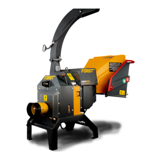
P a g e Purpose of machine The Forst PT6 is designed to reduce wood material up to 150mm diameter to woodchip. This machine is capable of processing up to 5 tonnes of wood per hour. -
Page 6: Exterior Component Identification
P a g e Exterior component identification Figure 1 ITEM NO. PART DESCRIPTION Trip Bar Control Valve Feed Speed Adjustment Hopper Tray latch Hopper Chipping Chamber Cover Chute Hood Chute Chamber Cover Machine Lifting Eye Chipping Chamber Grease Point Control Panel Feed Start/Stop Touch Sensors Hopper Tray... -
Page 7: Safe Working
P a g e Safety Safe working Before using this machine, make sure that you are trained and fluent in its operation. Know the location of and how to use all the safety features. Know how to control the feed and stop the machine in an emergency. Be familiar with the hazards and safe working practices to prevent injury and damage to property and machine. -
Page 8: Machine Lifting
P a g e 9. Never climb onto the hopper area while the machine is in operation. 10. Material can be forcibly ejected from the hopper towards the operator. Ensure full head and face protection is worn. 11. Very twisted material should be trimmed into manageable pieces. Failure to do this can result in material extending outside the hopper, moving aggressively side-to-side creating a hazard to the operator. -
Page 9: Dos And Don'ts
P a g e DOs and DON’Ts DO NOT use machine in poor visibility DO stop the machine before making or insufficient light to see clearly. any adjustments, refuelling or DO NOT use or attempt to start the cleaning. machine without the discharge chute DO make sure the machine has or guards correctly and securely fitted. -
Page 10: Noise Test Information
P a g e Noise test information Machine Forst PT6 Notes Tested chipping 50 x 50mm sawn pine 4.2m in length. Noise levels above 85dB (A) will be experienced at the working position and within a 4 metre radius. Operators and personnel within a 4 metre radius must wear appropriate ear protection at all times while machine is in operation to prevent the risk of hearing damage. -
Page 11: Machine Operation
P a g e | 10 Machine operation MACHINE USE TOUCH SENSOR HOPPER STAGE Fold down hopper tray Ensure Tactor and Chipper are on leval ground Ensure tractor horsepower and lift arm capacity match that of the chipper Start Tractor Allow engine to run for 30 seconds then open throttle to 540rpm For forward feed, touch green button... -
Page 12: Machine Control Panel, Start/Stop & Operating Settings
P a g e | 11 Machine control panel, start/stop & operating settings This machine is fitted with an engine PLC (Programmable Logic Controller) system that manages the engine, feed and all safety features. The control panel is located on the right side panel (see Figure 1). Feed and engine speed are controlled with a “No Stress”... - Page 13 P a g e | 12 When cable connected to Tractor Display will automatically go to P1 P1 shows Working Hours and charging indicator text at the screen bottom centre. P2 shows I/O tests. Tests all functions and safety controls. Pin screen P3 shows No-Stress Settings Actual RPM...
-
Page 14: Feed Speed Adjustment
P a g e | 13 Feed speed adjustment 1 CONTROL VALVE FEED SPEED ADJUSTMENT. POSITION INDICATED BY PIP. 0 = MINIMUM 10 = MAXIMUM Figure 4 The feed speed can be adjusted to suit the material being chipped see Figure . Turn dial to align number with pip. - Page 15 P a g e | 14 If feed becomes jammed: 1. Stop the engine and remove ignition key. 2. Open engine and chipping chamber covers. 3. Release feed roller spring tension on both sides by slackening off the eye bolt nuts and remove if necessary.
-
Page 16: Attaching To The Tractor
P a g e | 15 Attaching to the Tractor Ensure tractor horsepower and lift arm capacity are matched to the chipper and has a PTO speed of 540rpm Ensure both tractor and chipper are on level ground ... -
Page 17: Disconnecting From The Tractor
P a g e | 16 Disconnecting from the Tractor Ensure both tractor and chipper are on level ground Ensure The tractor PTO is disengaged and handbrake applied Lower the chipper to the ground, making sure the chipper is stable on the ground ... -
Page 18: Fastener Tightening Torques
P a g e | 17 Check all hydraulic hoses and fittings after 5 hours’ work. Beware of hydraulic oil leaks, they can cause serious injury while the engine is running and the system is under pressure. A leak can easily inject high pressure oil deep into flesh and blood stream requiring immediate medical attention. - Page 19 P a g e | 18 Service schedule Service Schedule After first Every 8 After first After first Every 20 After first Every 50 Every Every Every 5 Hrs 10 Hrs 20 Hrs 50 Hrs 100 Hrs 200 Hrs 250 Hrs Wood chipper (Daily) (weekly)
-
Page 20: Blade Sharpening
P a g e | 19 Blade sharpening For optimum performance, blades need to be kept sharp. Minimum safe blade size after sharpening as shown. After sharpening, the blade gap must be re-set by using a blade shim as shown. Shims are available in thicknesses of 0.5, 1, 1.5, 2 & 2.5mm as part number 12-03-093. -
Page 21: Hydraulic Oil Filter
P a g e | 20 1 SIDE ANVIL 2 ANVIL 3 OUTSIDE BLADE GAP 4 FLYWHEEL BLADE 5 INSIDE BLADE GAP Figure 8 Hydraulic oil filter Item Description Quantity Complete filter Filter element Seal kits O-ring for filter element O-ring for housing Anti-extrusion ring Gasket... - Page 22 P a g e | 21 Use protective plastic gloves to keep oil off skin, dispose of oil and filter in an environmentally responsible manner. 1. The filter housing is accessed via the left side panel. Thoroughly clean around filler housing before removing to help prevent debris getting into oil. 2.
-
Page 23: Drive Belt Tension
P a g e | 22 Drive belt tension Both Hydraulic pump and flywheel V belts must be checked for tension and condition. If any belt shows signs of wear, surface damage, shredding, excessive glazing, or have been stretched to their limit, they must be replaced. Multiple belt drives must have all belts replaced at the same time. -
Page 24: Hopper Tray Touch Sensor
P a g e | 23 arts lists Hopper tray touch sensor... -
Page 25: Chipping Chamber Assembly
P a g e | 24 Chipping chamber assembly... - Page 26 P a g e | 25 Chipping chamber assembly - Bottom feed.
-
Page 27: Chipping Chamber Assembly - Bottom Feed & Anvil
P a g e | 26 Chipping chamber assembly - Bottom feed & anvil. -
Page 28: Chipping Chamber Assembly - Drive
P a g e | 27 Chipping chamber assembly - Drive... -
Page 29: Chipping Chamber Assembly - Flywheel Drive
P a g e | 28 Chipping chamber assembly - Flywheel drive. Item No Part No Description Quantity 12-10-056 V belt 17 x 1975mm Ld 3... -
Page 30: Chipping Chamber Assembly - Bottom Feed Roller Cover
P a g e | 29 Chipping chamber assembly - Bottom feed roller cover. Item No Part No Description Quantity 12-12-504 M10 x 20Lg 8.8 Hex Head screw 2 12-14-010 M10 Spring Washer DIN 128 12-14-009 M10 Washer ISO 7089 12-03-045 Feed roller cover... -
Page 31: Chute Assembly
12-13-003 M12 nyloc nut ISO 7040 12-01-043 Hood hinge stud 12-19-151 Chute hood fab assy 12-30-024 Forst small orange decal 12-15-020 M12 Elastomer washer OD 25-ID 12 x 5 THK 12-19-055 Chute handle - standard 12-10-004 M12 female steel handle... -
Page 32: Top Feed Roller Assembly
P a g e | 31 Top feed roller assembly... -
Page 33: Flywheel Assembly
P a g e | 32 Flywheel assembly... -
Page 34: Flywheel Belt Tensioner Assembly
P a g e | 33 Flywheel belt tensioner assembly Item No Part No Description Quantity 12-12-1104 M16 x 110Lg 8.8 Hex Head bolt 12-14-019 M16 Spring washer DIN 128 12-14-005 M16 Washer ISO 7089 10mm Spacer between 3 and 8 12-11-011 6304 2RS Deep groove ball bearing 52 OD, 20 ID, 15 wide 12-01-036 Flat idler pulley-2x 17 V belt 12-01-024 Flat idler pulley shaft-2x 17 V belt... -
Page 35: Hydraulic Pump Assembly
P a g e | 34 Hydraulic pump assembly... -
Page 36: Pto Assembly Parts
P a g e | 35 PTO Assembly parts drawing... -
Page 37: Hydraulics Circuit Diagram
P a g e | 36 Hydraulics circuit diagram 1 Motor 2 Control valve 3 Test point 4 Filter 5 Pump 6 Oil tank... -
Page 38: Electrical Circuit Diagram - Pto Touch Sensor Hopper
P a g e | 37 Electrical circuit diagram – PTO touch sensor hopper... -
Page 39: Decals
P a g e | 38 Decals Decal meaning: 1. Throttle movement relation to engine speed. 2. CE (Conformite Europeene or European Conformity) mark. Manufacturer’s declaration that the product complies with the essential requirements of the relevant European health, safety and environment protection legislation. 3. -
Page 40: Manufacturer's Statutory Plate
P a g e | 39 Manufacturer’s Statutory Plate Information on the Manufacturer’s Statutory Plate in line order from top to bottom is as follows: 1. Manufacturing company. 2. Vehicle type approval number and construction date. 3. 17 digit Vehicle Identification Number (VIN) construction. 4. -
Page 41: Warranty
To obtain warranty service please contact Redwood Global Ltd for the nearest approved Forst Dealer. Your nearest dealer can be obtained from Redwood Global Ltd at the address on the front of the User Manual. In the event of a failure Redwood... -
Page 42: Ce Certificate
Redwood Global Ltd declares that their: Wood Chippers listed as the following models ST6 Towed & TR6 on Tracks ST8 Towed & TR8 on Tracks PT6 PTO & PT8 PTO are classified within the following EU Directives: Machinery Directive 2006/42/EC Electromagnetic Compatibility Directive 2004/108/EC...
Need help?
Do you have a question about the PT6 and is the answer not in the manual?
Questions and answers