Sign In
Upload
Download
Add to my manuals
Delete from my manuals
Share
URL of this page:
HTML Link:
Bookmark this page
Add
Manual will be automatically added to "My Manuals"
Print this page
×
Bookmark added
×
Added to my manuals
Manuals
Brands
Immergas Manuals
Boiler
VICTRIX 20 Plus
Manual
Immergas VICTRIX 20 Plus Manual
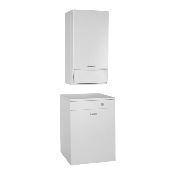
Condensation-type wall-hung room sealed fan-assisted boiler for central heating only or with an external storage tank
Hide thumbs
1
2
3
4
5
6
7
8
9
10
11
12
13
14
15
16
17
18
19
20
21
22
23
24
25
26
27
28
29
30
31
32
page
of
32
Go
/
32
Bookmarks
Advertisement
Quick Links
Download this manual
VICTRIX Plus
Condensation-type wall-hung
room sealed fan-assisted boiler
for central heating only
or with an external storage tank.
Table of
Contents
Previous
Page
Next
Page
1
2
3
4
5
Advertisement
Need help?
Do you have a question about the VICTRIX 20 Plus and is the answer not in the manual?
Ask a question
Questions and answers
Related Manuals for Immergas VICTRIX 20 Plus
Boiler Immergas VICTRIX 20X TT 1E Instruction And Warning Book
(40 pages)
Boiler Immergas VICTRIX 20X TT 1E Instruction And Warning Book
(40 pages)
Boiler Immergas INOXSTOR 200 V2 Instruction And Recomendation Booklet
Storage tank (16 pages)
Boiler Immergas INOXSTOR 200 V2 Manual
(8 pages)
Boiler Immergas LUXOR 16 V2 Instructions And Warnings
Pellet boiler (52 pages)
Boiler Immergas VICTRIX 26 2 I Manual
Condensation-type wall-hung boiler (62 pages)
Boiler Immergas Victrix-Zeus-Superior 32 KW I Instruction Booklet And Warning
(40 pages)
Boiler Immergas HERCULES CONDENSING ErP Series Instruction And Recommendation Booklet
(52 pages)
Boiler Immergas Hercules Condensing 26 3 ErP Instruction And Recommendation Booklet
(52 pages)
Boiler Immergas VICTRIX 24 kW Manual
Instant wall-hung boilers condensation-type, condensation-type wall-hung boiler for central heating only or with an external storage tank (52 pages)
Boiler Immergas NIKE MYTHOS 24 2E Series Instruction And Warning Book
(24 pages)
Boiler Immergas MINI EOLO 24 3E Instruction And Warning Book
(36 pages)
Boiler Immergas VICTRIX ZEUS SUPERIOR 25 Instructions And Recommendations
(128 pages)
Boiler Immergas HERCULES SOLAR 26 1A Manual
Ecological floor-standing condensing boiler with stainless steel storage tank integrate with solar circuit (68 pages)
Boiler Immergas EOLO STAR 24 5E Instruction Manual
(36 pages)
Boiler Immergas VICTRIX 27 Plus Manual
Condensation-type wall-hung room sealed fan-assisted boiler for central heating only or with an external storage tank (32 pages)
This manual is also suitable for:
Victrix 27 plus
Print
Rename the bookmark
Delete bookmark?
Delete from my manuals?
Login
Sign In
OR
Sign in with Facebook
Sign in with Google
Upload manual
Upload from disk
Upload from URL


Need help?
Do you have a question about the VICTRIX 20 Plus and is the answer not in the manual?
Questions and answers