Table of Contents
Advertisement
Advertisement
Table of Contents

Related Manuals for PROEMION CANlink wireless 4000 Series


Summary of Contents for PROEMION CANlink wireless 4000 Series
- Page 1 CANlink wireless 4000 Device Manual...
-
Page 2: Table Of Contents
CANlink wireless 4000 Device Manual 1. Preamble ................. . . 1 1.1. -
Page 3: Preamble
CANlink wireless 4000 Device Manual 1. Preamble Figure 1. CANlink wireless 4000 series 1.1. Legal Notice All brands and trademarks named in this document and possibly protected by third-party rights are subject without limitation to the terms of the valid trademark law and intellectual property rights of their respective registered owner. -
Page 4: Contact
CANlink wireless 4000 Device Manual 1.2. Contact Proemion GmbH Donaustr. 14 36043 Fulda, Germany Phone: +49 661 9490-0 Fax: +49 661 9490-111 info@proemion.com Proemion Corp. US Subsidiary 241 Taylor St., Suite 301 Dayton, Ohio 45402, USA Phone: +1 937 558 2211 Fax: +1 937 641 8787 info-dayton@proemion.com... - Page 5 CANlink wireless 4000 Device Manual 1.3.2. Symbols and formatting The following symbols and formatting help you recognize the purpose of the paragraphs: DANGER Nature and source of the danger Consequences of non-observance - Measures to avoid the danger WARNING ...
-
Page 6: About The Device
CANlink wireless 4000 Device Manual Symb Description Description of different Models/Types. Data and descriptions that only apply to certain Models/Types are either covered in separate chapters or marked with the symbol shown here. 2. About the Device This chapter provides an overview of the device’s operating elements and functions as well as the intended use of the device. - Page 7 CANlink wireless 4000 Device Manual # Item 9 Pressure compensation element INFORMATION The CANlink wireless 4001 does not feature an external antenna connector. The antenna is integrated in the device.
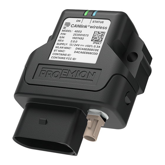
- Page 8 CANlink wireless 4000 Device Manual 2.1.2. Type Label The type label on top provides the following information: Figure 3. CANlink wireless 4000 type label top Table 2. Device Type labels Item Model designation Type Part number Serial Number Power supply WLAN MAC address Bluetooth MAC address FCC-ID...
- Page 9 CANlink wireless 4000 Device Manual Figure 4. CANlink wireless 4000 type label bottom Table 3. Device Type labels # Item 1 Manufacturer address 2 Country of origin 3 ECE certification mark NOTICE Use of solvents on the product label can remove or destroy product information. - Keep solvent-containing substances away from the label! NOTICE ...
- Page 10 CANlink wireless 4000 Device Manual Item Description (B) followed by the Bluetooth MAC Address: D4CA6E868CDD...
- Page 11 - The device must only be put into operation by qualified technicians and electricians with advanced knowledge of electrical engineering and fieldbus systems The CANlink wireless 4000 series can be used in environments that require protection class IP6K7. INFORMATION ...
- Page 12 CANlink wireless 4000 Device Manual NOTICE Risk of Property damage. Device is not installed in accordance with the setup requirements and permitted environmental conditions. - The system integrator is responsible to install the device according to the specification and take ...
- Page 13 CANlink wireless 4000 Device Manual 2.1.4. Conformity For details of the corresponding approval tests, see Certification and Qualification. The device meets the requirements of the following standards and legal requirements: CE Compliant This device complies with the directives, standards and normative documents listed in Certification and Qualification.
-
Page 14: Device Functions
CANlink wireless 4000 Device Manual 2.2. Device Functions The available Model and Types differ in the external antenna connector. With the device, you can transmit and receive CAN data via a WLAN or Bluetooth connection. It can also be used as a CAN-CAN Bridge or a CAN-Wireless Interface. - Page 15 CANlink wireless 4000 Device Manual 2.2.2. Scope of Delivery • CANlink wireless 4000 • Leaflet with instructions for downloading the documentation • simplified CE Declaration of conformity...
- Page 16 CANlink wireless 4000 Device Manual 2.2.3. Launch Kit For the initial setup of the device, an additional launch kit with the following components is available for ordering: Table 7. CANlink wireless 4000 Launch kit (part number 253000187) Material CLW4K Starter Cable 6open 2dsub 1pw 2m 1 Cable MTII 14pin code1 open 2m ANT WLDB DA 2M0 FAKRA-I FA CANview USB...
- Page 17 Library. Table 8. Software Software Source CANlink wireless configurator Download Center Remote Service Tool Download Center Proemion Firmware Programmer Download Center RM CAN-Device Monitor Download Center Dashboard App Google Play Table 9. Accessories SAP Part Number / Ordering Material short text...
-
Page 18: Service And Support
CANlink wireless 4000 Device Manual 2.3. Service and Support For more information visit the Support website and contact the technical support department by using our Support Form. The latest versions of the drivers, software, firmware, and documentation can be found on our Download Center. - Page 19 Danger to life due to electric shock! Risk of severe or fatal injury. - Never carry out repairs to the device yourself. Contact the Proemion support. The device does not contain any parts that can be repaired or maintained by the user. WARNING Overload damage due to malfunction.
- Page 20 CANlink wireless 4000 Device Manual NOTICE Risk of property damage. - The device must be installed, connected, and commissioned by a qualified technician. - Disconnect the device completely before handling it. - Also disconnect any independently supplied output load circuits. - Provide all the device connectors with plugs and any protection caps required to ensure ...
-
Page 21: Ce Notes European Union
CANlink wireless 4000 Device Manual 3.2. CE Notes European Union The devices described in this device manual may only be used in mobile or stationary systems in which the distance between antennas and persons is at least 20 cm. Furthermore, antennas may only be operated in conjunction with other antennas or transmitters when the correct horizontal distance between them is observed. -
Page 22: Ukca Notes United Kingdom
CANlink wireless 4000 Device Manual 3.3. UKCA Notes United Kingdom The devices described in this device manual may only be used in mobile or stationary systems in which the distance between antennas and persons is at least 20 cm. Furthermore, antennas may only be operated in conjunction with other antennas or transmitters when the correct horizontal distance between them is observed. -
Page 23: Fcc Notes Usa
CANlink wireless 4000 Device Manual 3.4. FCC Notes USA The devices described in this device manual may only be used in mobile or stationary systems in which the distance between antennas and persons is at least 20 cm. The antennas must further not be co-located or operated in conjunction with any other antennas or transmitters. -
Page 24: Ised Notes Canada
CANlink wireless 4000 Device Manual 3.5. ISED Notes Canada English This product meets the applicable Innovation, Science and Economic Development Canada technical specifications. This Class B equipment complies with the applicable ISED RSSs Standards and CAN ICES-003. Operation is subject to the following two conditions: (1) This device may not cause interference, and (2) This device must accept any interference, including interference that may cause undesired operation of the device. - Page 25 CANlink wireless 4000 Device Manual 5GHz-bande de fréquence. AVERTISSEMENT Interférences nuisibles Cet appareil est limité à un fonctionnement en intérieur uniquement dans la bande 5150-5250 MHz pour réduire le potentiel d’interférences nuisibles aux systèmes mobiles par satellite sur le même canal.
-
Page 26: Warranty And Liability
CANlink wireless 4000 Device Manual 3.6. Warranty and Liability Proemion assumes no liability for defects caused by normal wear, external influences and incorrect installation, operation or maintenance. This also applies if the customer or a third party modifies the devices, any accessories, or the software without permission from Proemion. - Page 27 CANlink wireless 4000 Device Manual 4.1.1. CAN-Bluetooth Interface In operation as a CAN-Bluetooth Interface, CAN data is transmitted wirelessly to other Bluetooth-capable devices such as PCs, smartphones, or tablets.
- Page 28 CANlink wireless 4000 Device Manual 4.1.2. CAN-WLAN Interface In operation as a CAN-WLAN Interface, CAN data is transmitted wirelessly to other WLAN-capable devices such as PCs, smartphones, or tablets.
- Page 29 CANlink wireless 4000 Device Manual 4.1.3. CAN-CAN-Bluetooth Bridge In operation as a CAN-CAN-Bluetooth Bridge, CAN data is transmitted wirelessly between two CANlink wireless 4000 devices via a Bluetooth connection. The CAN-CAN-Bluetooth Bridge acts as a substitute for CAN cables, e.g. in drag chains or remote control units.
- Page 30 CANlink wireless 4000 Device Manual 4.1.4. CAN-CAN-WLAN Bridge In operation as a CAN-CAN-WLAN Bridge, CAN data is transmitted wirelessly between two CANlink wireless 4000 devices via a WLAN connection. The CAN-CAN-WLAN Bridge acts as a substitute for CAN cables, e.g. in drag chains or remote control units.
- Page 31 Connectio Remarks Client Software n Method CAN – Mobile Device / Bluetooth Proemion Dashboard App for Android, 3rd Party PC Interface, P2P Classic App for Android or iOS via Byte Command connection Protocol API, Remote Service Tool software CAN – Mobile Device /...
-
Page 32: Connectors
CANlink wireless 4000 Device Manual 4.2. Connectors The device is equipped with the following connectors: • 1x main plug connector, code 1 (14-pin) : CAN1 / CAN2 / VCC / GND / AIN1-2 / DOUT • 1x RF antenna connector - FAKRA, code I (male) NOTICE According to the manufacturer’s information, the connectors are equipped for the following minimum number of mating cycles:... - Page 33 CANlink wireless 4000 Device Manual The main plug connector is designed for a minimum number of 10 mating cycles. If the minimum number of mating cycles is exceeded, individual parameters could be out of the specification. The basic function of the main plug connector remains intact. Please be aware that the process of the CANlink wireless system integration is not designed for a high number of mating cycles.
- Page 34 CANlink wireless 4000 Device Manual Figure 8. Disconnect main plug connector...
- Page 35 CANlink wireless 4000 Device Manual 4.2.2. RF Antenna Using the FAKRA antenna connector (Type 4003), connect the device with an RF antenna to receive WLAN / Bluetooth signals. Figure 9. RF antenna connector for Type 4003 (FAKRA, male) Table 13. Pin layout of RF antenna, Type 4003 Designatio Description inner pin...
- Page 36 CANlink wireless 4000 Device Manual Disconnect antenna connector Release the marked lock and carefully pull the plug backwards. Figure 11. Disconnect antenna connector...
-
Page 37: Indicator Element (Led)
CANlink wireless 4000 Device Manual 4.3. Indicator Element (LED) The front of the device features two RGB LEDs for indicating function and status. Figure 12. LEDs The following table shows possible LED states: Table 14. ON LED Color Status Meaning Device is switched off or in sleep mode. - Page 38 CANlink wireless 4000 Device Manual Color Status Meaning Orang Single Flash Device received CANopen SDO request Orang CAN1 Error. CAN2 Error. Turquo Device is in Radio Module Update Mode (via HTTP Server) (also ON LED is Turquoise). Pink Active connection with CANlink wireless configurator. The ON LED is also pink in parallel.
-
Page 39: Cables
CANlink wireless 4000 Device Manual 4.4. Cables 4.4.1. Start Cable / Main Plug Connector The cable CLW4K Starter Cable 6open 2dsub 1pw 2m (part number 136000197) is equipped with the following connectors and open individual wires: • 1 micro timer II socket,14-pin, female •... - Page 40 CANlink wireless 4000 Device Manual Figure 14. Individual wires open Table 17. Start cable for main plug connector, individual wires open Designation Color Description Terminal 31 / ground Green Power supply Analog input 1 Yellow I/O input Analog input 2 Gray I/O input Not used...
- Page 41 CANlink wireless 4000 Device Manual Designation Color Description Terminal 31 / ground Green CAN1-High White-green CAN, bidirectional not assigned Terminal 30 / VCC White Power supply The D-Sub connector (CAN1) connection is also equipped with a slide switch to complete a reset to the factory settings.
- Page 42 CANlink wireless 4000 Device Manual 4.4.2. Custom Cable for Main Plug When creating a customized cable harness for the system integration of the CANlink wireless 4000, some important recommendation for the setup of the main plug connector and cable must be considered. It is recommended to use the connector components from the Software and Accessories list to create a custom cable harness.
- Page 43 CANlink wireless 4000 Device Manual 4.4.3. Cable Management NOTICE Risk of property damage. * Fasten the cable harness with a suitable strain relief near the main plug connector in order to avoid the transmission of any tension, strains or vibrations. * Ensure that there is minimum bending radius of 8 time the outer diameter of the cable harness.
- Page 44 CANlink wireless 4000 Device Manual Symbol Part Numbers 7807624...
-
Page 45: Getting Started
You can evaluate the transmitted data with the Remote Service Tool software or the RM CAN-Device Monitor. The Dashboard app enables you to display data on a smartphone (Android). Use the Proemion Firmware Programmer software for firmware updates. The software can be downloaded from our... -
Page 46: Connecting The Device
CANlink wireless 4000 Device Manual 5.2. Connecting the Device WARNING Overload damage due to malfunction. Risk of severe or fatal injury. - To limit power in the event of malfunction, secure the DC power supply circuit during installation with an external 1A fuse. NOTICE Risk of property damage. - Page 47 - Keep the length of the antenna cable as short as possible. - In case of using the antennas which are supplied with the hardware kit or as Proemion accessories: Ensure that the minimum bending radius of the antenna cables is 8 times the outer diameter.
- Page 48 CANlink wireless 4000 Device Manual 5.2.2. CAN Connect the device interfaces to the CAN bus whose data you want to log or send. For test purposes, connect the device to a PC using a communication gateway (e.g. CANview USB). The CAN connection terminal CAN-High and CAN-Low signals must match the signals of the connector on the device. You can connect Ground of the supply connector with CAN-GND because there is no galvanic isolation.
- Page 49 CANlink wireless 4000 Device Manual 5.2.3. CAN bus termination In any bus system, signal reflections at the end of a wire or cable can cause interference which can in turn cause transmission errors. To minimize these reflections, place a terminator at each end of transmission lines. The terminating resistance between CAN-High and CAN-Low must match the characteristic impedance of the transmission cables.
- Page 50 CANlink wireless 4000 Device Manual 5.2.4. Power supply The device is supplied with power via the CAN connector. When switching on, terminal 30 must always be connected to the power supply before terminal 15 changes to status high. Otherwise the device may not initialize correctly. ...
- Page 51 CANlink wireless 4000 Device Manual 5.2.5. Connection with a PC via Bluetooth To connect the device with a PC for configuration and firmware update purposes, you need the components from the Launch Kit. 1. Connect the Start Cable / Main Plug Connector 2.
- Page 52 CANlink wireless 4000 Device Manual Figure 26. Add a Device 8. Click on Unknown device. Figure 27. Add a Device - Unknown Device 9. When the message Your device is ready to go! appears, click on Done.
- Page 53 CANlink wireless 4000 Device Manual Figure 28. Add a Device - Done Ensure that the displayed serial number is matching the serial number at the type label. 10. Click on More Bluetooth options.
- Page 54 CANlink wireless 4000 Device Manual Figure 29. More Bluetooth Options 11. Click on the COM Ports page tab. Figure 30. Bluetooth Settings 12. Make a note of the Outgoing COM port and close the Bluetooth settings dialog. The number of the Outgoing com port needs to be selected when using the CANlink wireless 4000 with the CANlink wireless configurator , Remote Service Tool or other software tools.
- Page 55 CANlink wireless 4000 Device Manual Figure 31. Bluetooth Settings - COM Ports ¬ The CANlink wireless 4000 is paired with your pc and is ready to use. If the new CANlink wireless 4000 was not discovered and paired, a reset to the factory settings might be necessary.
- Page 56 CANlink wireless 4000 Device Manual 5.2.6. Create Support Archive The CANlink wireless configurator software incorporates the option to create a backup of the installed device configuration and static device parameters. This function can be used to save the original configuration and device information such as software version, WiFi and Bluetooth MAC address, etc.
- Page 57 CANlink wireless 4000 Device Manual Example of device information file (details.txt): Date and time: 16.03.2022 07:41:50 APPLICATION Name: CANlink wireless Configurator Version: 4.1.0.1 DEVICE ------ ID string: CANlink wireless 4xxx 1.x.x 2.0 01004001 <RS> Serial number: 2148007 Product code: 1004001 Vendor ID: 524D Product group: 120 UNIX time of manufacture: 06.12.2021 06:53:19 UTC...
-
Page 58: Configuring The Device
CANlink wireless 4000 Device Manual 5.3. Configuring the Device The following chapters will give an overview of the required configuration settings for the several options which are mentioned in the Use Cases Overview. The settings for each section, the tabs Device, WLAN, Bluetooth and Wireless Peers are listed in separate tables. - Page 59 CANlink wireless 4000 Device Manual 5.3.1. CAN – Mobile Device / PC Interface P2P Bluetooth WLAN Table 23. CAN – Mobile Device / PC Interface Bluetooth, Tab WLAN Section Paramete Setting WLAN Settings Enable Disabled Bluetooth Table 24. CAN – Mobile Device / PC Interface Bluetooth, Tab Bluetooth Section Parameter Setting...
- Page 60 CANlink wireless 4000 Device Manual 5.3.2. CAN – Mobile Device / PC Interface P2P WLAN Access Point mode WLAN Table 26. CAN – Mobile Device / PC Interface P2P WLAN Access Point mode, Tab WLAN Section Parameter Setting WLAN Enable Enabled Settings WLAN...
- Page 61 CANlink wireless 4000 Device Manual 5.3.3. CAN – Mobile Device / PC Interface P2P WLAN Infrastructure mode WLAN Table 29. CAN – Mobile Device / PC Interface P2P WLAN Infrastructure mode, Tab WLAN Section Parameter Setting WLAN Settings Enable Enabled WLAN Settings Operating Mode Infrastructure WLAN Settings SSID...
- Page 62 CANlink wireless 4000 Device Manual 5.3.4. CAN – CAN Bridge P2P Bluetooth Classic CAN – CAN Bridge P2P Bluetooth Classic - SPP Server WLAN Table 32. CAN – CAN Bridge P2P Bluetooth, SPP Server, Tab WLAN Section Paramete Setting WLAN Settings Enable Disabled Bluetooth Table 33.
- Page 63 CANlink wireless 4000 Device Manual Wireless Peers Table 37. CAN – CAN Bridge P2P Bluetooth, SPP Client, Tab Wireless Peers Section Parameter Setting Servers Leave the server settings empty. Clients Enabled Client Configuration Type Client Configuration Enable Enabled Client Configuration MAC address Enter BT MAC address of the device which is to be used as SPP Server module...
- Page 64 CANlink wireless 4000 Device Manual 5.3.5. CAN – CAN Bridge P2P WLAN Access Point mode CAN – CAN Bridge P2P WLAN Access Point mode - TCP Server WLAN Table 38. CAN – CAN Bridge P2P WLAN Access Point mode, TCP Server, Tab WLAN Section Parameter Setting...
- Page 65 CANlink wireless 4000 Device Manual Section Parameter Setting WLAN Settings Enable Enabled WLAN Settings Operating Mode Infrastructure WLAN Settings SSID Set the same SSID like for the WLAN AP (TCP Server) WLAN Settings Authentication Type According to the settings of the WLAN AP (TCP Server) WLAN Settings Authentication Key According to the settings of the WLAN AP (TCP Server) IP Settings...
-
Page 66: Hardware Installation
CANlink wireless 4000 Device Manual 5.4. Hardware installation This chapter provides important notes regarding the hardware setup. NOTICE Risk of property damage. - Fasten the cable harness with a suitable strain relief near the CAN / power connector to avoid the transmission of any tension, strains, or vibrations. - Page 67 * Do not extend the antenna cable. * Only use the antennas which are supplied as accessories by Proemion. * Change the mounting position of the CANlink wireless to reduce the distance between antenna and the CANlink wireless or order an alternative antenna with longer antenna cable.
- Page 68 CANlink wireless 4000 Device Manual 5.4.2. Mounting Orientations The view elements of the two LEDs on the device do not comply with the flammability class required for a fire protection housing. Fire protection of the housing is only guaranteed in the installation positions shown in figures A, B, C or D. Please note that fire protection is not guaranteed in the installation positions shown in figures I and II.
- Page 69 CANlink wireless 4000 Device Manual 5.4.3. Internal Antenna The internal antenna of the CANlink wireless variant 4001 is located on the top side of the PCB, therefore it is recommended to mount the device in such a way that the top side also has the best possible alignment and free sight to its peer.
- Page 70 - Do not extend the antenna cable. Only use the antennas which are supplied as accessories by Proemion. Bring the radio module closer to the antenna or order an alternative antenna with a longer antenna cable. - An antenna, particularly outside, should be positioned as high as possible. This allows you to improve the range.
-
Page 71: Operation
CANlink wireless 4000 Device Manual 5.4.5. Mounting Below you will find instructions on how to mount the device. Directly affix the device with two flat headed screw ISO 14583 M6X30 TX which are at least 30 mm long. Tighten the bolts with a torque of 3,4 Nm +/- 10%. - Page 72 CANlink wireless 4000 Device Manual Figure 36. CANlink wireless configurator The software can be downloaded from our Download Center at the Document Library. In this document, only the basic settings for the individual connection methods are listed in chapter ...
- Page 73 CANlink wireless 4000 Device Manual 6.1.2. Tooltips Additional information regarding individual configuration options in CANlink wireless configurator software can be found within the Tooltips. Always use the latest version of CANlink wireless configurator software with the updated tool tips. Figure 37. CANlink wireless configurator Tooltip - Example SPP Server 6.1.3.
-
Page 74: Can Functions
CANlink wireless 4000 Device Manual 6.2. CAN functions This chapter provides information on how to use and configure CAN functions. - Page 75 CANlink wireless 4000 Device Manual 6.2.1. CAN / CANopen The CANlink wireless 4000 supports the transmission of pure CAN messages to another device. No direct protocol interpretation is configured in the firmware. This makes it possible to use the device for different applications with various CAN transport protocols.
- Page 76 CANlink wireless 4000 Device Manual 6.2.2. Enabling the CANopen Stack The CANopen stack prevents the transmission of some CAN messages such as CANopen RX SDOs, TX SDOs, and emergency messages. These messages are received by the device’s CANopen stack and processed to the radio Interface without being forwarded on.
- Page 77 CANlink wireless 4000 Device Manual 6.2.3. Boot-Up message Directly after startup, the device optionally transmits a CANopen boot-up message with its own node ID. 1. To enable the Boot-Up message, the Advanced Settings must be activated within the CANlink wireless configurator software first.
- Page 78 CANlink wireless 4000 Device Manual 6.2.4. Filter received CAN messages The device offers the option of configuring message filters. This allows you to reduce the transmission load and ensure that the CAN bus only transmits certain CAN messages. In the CAN Receive tab of the CANlink wireless 4000 Configurator you can set filter masks and activate or deactivate individual bits for the comparison function of online CAN objects.
- Page 79 CANlink wireless 4000 Device Manual Online CAN object Binary 11-bit CAN identifier (hex): 0x124 001 0010 0100 11-bit CAN identifier (hex): 0x125 001 0010 0101 XNOR gate for filter mask 111 1111 1000 Resulting Filter mask (hex) 0x7F8 111 1111 1xxx Filter Calculation Example 3: CAN messages with the CAN identifiers 0x123, 0x124, and 0x125, 0x621, and 0x726 are transmitted.
-
Page 80: Firmware Update
CANlink wireless 4000 Device Manual 6.3. Firmware update To perform a firmware update, you need the Proemion Firmware Programmer software and a CAN connection with the device via a CANview USB. The required software can be downloaded from the Download Center... - Page 81 CANlink wireless 4000 Device Manual Figure 43. Firmware Programmer - Search for Targets 7. Select the corresponding device. The default Node ID of the CAN 1 interface is 34 (dec) and the found device is displayed as 34: CANlink wireless 4xxx. 8.
- Page 82 CANlink wireless 4000 Device Manual Figure 44. Firmware Programmer - Update Complete 10. Exit the Proemion Firmware Programmer software INFORMATION The firmware update may reset or add configuration settings of the device. ¬ After the firmware update, load your configuration to the device with the latest version of the...
-
Page 83: Reset Device (Repair Mode)
CANlink wireless 4000 Device Manual 6.4. Reset device (repair mode) The repair mode resets the device to the firmware default settings. NOTICE Loss of custom configuration The repair mode reset wipes the configuration in the device. No roll-back is possible if the configuration is not read from the device and saved to a file with the CANlink wireless 4000 Configurator. - Page 84 CANlink wireless 4000 Device Manual ¬ Both LEDs light up green for a second and change to LED ON = steady green and STATUS = green blinking. To abort the device reset , disconnect the power supply while the LEDs are still orange and ...
-
Page 85: Troubleshooting And Maintenance
3. Firmware version of the device. 4. Support archive. See chapter Create Support Archive. 5. What is the LED status? Use the Support Form or just send an email to support@proemion.com to provide the required device information and description of the problem. -
Page 86: Maintenance
CANlink wireless 4000 Device Manual 7.2. Maintenance • Regularly check all connectors for a firm connection. • Regularly check the housing for cracks or any other damages. -
Page 87: Cleaning
CANlink wireless 4000 Device Manual 7.3. Cleaning NOTICE Risk of property damage Damage to the device due to water penetration - The device was tested against water jets according to IPxK6 of ISO 20653 standard. Different loads, e.g., with a pressure washer or a higher flow rate, do not correspond to the intended use. - Never clean the CANlink wireless 4000 device with a pressure washer or similar. - Page 88 CANlink wireless 4000 Device Manual Figure 45. Dimensions of CANlink wireless 4003 The dimension for the CANlink wireless 4001 are equal to the dimensions of the CANlink wireless 4003. The only difference is the external FAKRA connector at the CANlink wireless 4003.
-
Page 89: Technical Data
CANlink wireless 4000 Device Manual 10.2. Technical Data This chapter contains information on the technical data of the device. 10.2.1. Mechanical Table 49. Mechanical data Parameter Value Dimensions width/height/depth [mm] 67 / 84 / 32 Color Black Protection class IP6K7(if all connectors of the device are plugged in) Temperature range -40 °C ¬... - Page 90 CANlink wireless 4000 Device Manual 10.2.2. Electrical Table 50. Electrical data Parameter Value Supply voltage range terminal 30 DC Rated voltage 12V / 24V, Tolerance +-50%, range 6V to Power consumption, at 24 V (Operating < 80 mA Ø) Power consumption in sleep mode <...
- Page 91 CANlink wireless 4000 Device Manual 10.2.3. Interfaces NOTICE Please be aware that the measured performance values were determined in the free field without significant interference or signal dampening. The maximum range, latency and the possible message throughput may vary considerably depending on the environmental influences, setup ...
- Page 92 CANlink wireless 4000 Device Manual Parameter Value Data transfer rate Bluetooth single point: tbd CAN messages per CAN messages per second that can be transmitted second without data loss Tested with Baud rate: 1 Mbit/s WLAN Access Point, Single Point: tbd CAN messages per second WLAN infrastructure mode Single Point: tbd CAN messages per second...
- Page 93 CANlink wireless 4000 Device Manual * This function is not available with the current firmware yet. It will be supported by the upcoming firmware. 10.2.4. CAN-WLAN Interface In operation as a CAN-WLAN Interface, CAN data is transmitted wirelessly to other WLAN-capable devices such as PCs, smartphones or tablets.
- Page 94 CANlink wireless 4000 Device Manual Protocols Table 54. Protocols Protocol Available Layer 2 CANopen Customer-specific On request Serial Port Profile (SPP) RM Byte Command Protocol Yes...
- Page 95 CANlink wireless 4000 Device Manual Status Indicators Table 55. Status indicators Varian Status indicator 4001 2 RGB LED 4003 2 RGB LED...
-
Page 96: Certification And Qualification
Chapter Service and Support. Hereby, Proemion GmbH declares that the radio equipment type CANlink® wireless 4000 is in compliance with Directive 2014/53/EU. The full text of the EU declaration of conformity is available at the following internet address Declaration of Conformity.
Need help?
Do you have a question about the CANlink wireless 4000 Series and is the answer not in the manual?
Questions and answers