Sign In
Upload
Download
Table of Contents
Contents
Add to my manuals
Delete from my manuals
Share
URL of this page:
HTML Link:
Bookmark this page
Add
Manual will be automatically added to "My Manuals"
Print this page
×
Bookmark added
×
Added to my manuals
Manuals
Brands
Aritech Manuals
Smoke Alarm
2X-A Series
Installation manual
Aritech 2X-A Series Installation Manual
Hide thumbs
Also See for 2X-A Series
:
Operation manual
(41 pages)
,
Quick operation manual
(2 pages)
1
2
3
4
5
6
7
8
9
10
11
12
13
14
15
16
17
18
19
20
21
22
23
24
25
26
27
28
29
30
31
32
33
34
35
36
37
38
39
40
41
42
43
44
45
46
47
48
49
50
51
52
53
54
55
56
57
58
59
60
61
62
63
64
65
66
67
68
69
70
71
72
73
74
75
76
77
78
79
80
81
82
83
84
85
86
87
88
89
90
91
92
93
94
95
96
97
98
99
100
101
102
103
104
105
106
107
108
109
110
111
112
113
114
115
116
117
118
119
120
121
122
123
124
125
126
127
128
129
130
131
132
133
134
135
136
137
138
139
140
141
142
143
144
145
146
147
148
149
150
151
152
153
154
155
156
157
158
159
160
161
162
163
164
165
166
167
168
169
170
171
172
173
174
page
of
174
Go
/
174
Contents
Table of Contents
Bookmarks
Table of Contents
Table of Contents
Important Information
Chapter 1 Introduction
Product Range
Product Compatibility
Product Overview
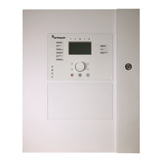
The User Interface
Front Panel Controls and Indicators
LCD Controls and Indicators
Acoustic Indicators
Conditions
Chapter 2 Installation
Electrical Safety
Cabinet and PCB Layout
Cabinet Installation
Where to Install the Control Panel
Fixing the Cabinet to the Wall
Adding the Menu Inserts
Connecting the User Interface Cable
Connecting the Internal Printer and Loading Paper
Battery Installation
Compatible Batteries
Installing Batteries
Connections
Recommended Cables
Overview of Fire System Connections
Connecting Loops
Connecting Inputs
Connecting Loop Devices
Connecting Outputs
Connecting the Mains Power Supply
Connecting the Batteries
Connecting a Fire Network
Connecting Expansion Boards
Connecting an External Printer or ASCII Terminal
Chapter 3 Configuration and Commissioning
Introduction
User Levels
Configuration Overview
Maintenance Level Operation and Configuration
The Field Setup Menu
The Panel Setup Menu
The Communications Menu
The Disable/Enable Menu
The Test Menu
The Reports Menu
The Password Setup Menu
Installer Level Operation and Configuration
Panel Configuration
The Main Menu
ID Configuration
Regional Options
Firenet Configuration
Communications Configuration
Other Settings
Load/Save Configuration
Expansion Board Configuration
Load Auxiliary Files
System Update
Printer Configuration
DACT Configuration
Panel Activation Key
Auto Date and Time
BMS Configuration
Autosetup
Field Configuration
Loop Device Configuration
Zone Configuration
Panel I/O Configuration
Activation Configuration
High-Power Loop Configuration
Loop Class Configuration
Remote Disable/Enable Configuration
Tests
Password Setup
Commissioning
Chapter 4 Maintenance
Fire Alarm System Maintenance
Battery Maintenance
Chapter 5 Technical Specifications
Loop Specifications
Power Supply Specifications
Battery and Battery Charger Specifications
Communication Port Specifications
Fire Network Specifications
Input and Output Specifications
LCD Specifications
Internal Printer Specifications
Mechanical and Environmental Specifications
Appendix A Default Configurations
Appendix Bpstn Country Codes
Appendix C Menu Maps
Appendix D Regulatory Information
Index
Advertisement
Quick Links
1
Important Information
Download this manual
2X-A Series Installation
Manual
P/N 00-3280-501-0003-01b • ISS 22NOV22
Table of
Contents
Previous
Page
Next
Page
1
2
3
4
5
Advertisement
Chapters
Table of Contents
3
Chapter 1 Introduction
7
Chapter 2 Installation
23
Chapter 3 Configuration and Commissioning
51
Chapter 5 Technical Specifications
143
Table of Contents
Need help?
Do you have a question about the 2X-A Series and is the answer not in the manual?
Ask a question
Questions and answers
Related Manuals for Aritech 2X-A Series
Fire Alarms Aritech 2X-AF2-FB-PRT-P Operation Manual
(41 pages)
Fire Alarms Aritech 2X-A Series Quick Operation Manual
(2 pages)
Smoke Alarm Aritech 2X-AF 2-F B-PRT-P Installation Manual
(174 pages)
Smoke Alarm Aritech 700 series Installation And Servise Manual
Commercial self-diagnostic smoke detectors (4 pages)
Smoke Alarm Aritech 560 Series Installation Instructions
Battery powered wireless smoke detector (3 pages)
This manual is also suitable for:
2x-af1-s
2x-af1-fb-s
2x-af1-scfb-s
2x-af2-s
2x-af2-fb-s
2x-af2-scfb-s
...
Show all
2x-afr-s
2x-afr-fb-s
2x-ae1
2x-af1
2x-af1-fb
2x-af1-scfb
2x-ae2
2x-af2
2x-af2-prt
2x-af2-fb
2x-af2-fb-prt
2x-af2-scfb
2x-afr
2x-afr-fb
2x-ae2-p
2x-af2-p
2x-af2-prt-p
2x-af2-fb-p
2x-af 2-f b-prt-p
2x-af2-scfb-p
Table of Contents
Print
Rename the bookmark
Delete bookmark?
Delete from my manuals?
Login
Sign In
OR
Sign in with Facebook
Sign in with Google
Upload manual
Upload from disk
Upload from URL


Need help?
Do you have a question about the 2X-A Series and is the answer not in the manual?
Questions and answers