Table of Contents
Advertisement
OPHTHALMIC ECHOGRAPH
BIOMETRY AND PACHYMETRY
SERVICE MANUAL
XE AX2 MT AN
OCTOBER 2009
Directive 93/42/EEC
QUANTEL MEDICAL
Head Office: 21, rue Newton, Z.I. du Brezet, 63039 Clermont-Ferrand cedex 2 - FRANCE
Tel : +33 (0) 473 745 745 - Fax : +33 (0) 473 745 700
E-mail:
contact@quantel-medical.fr
Web site:
www.quantel-medical.com
Advertisement
Table of Contents

Related Manuals for Quantel Medical Axis II PR


Summary of Contents for Quantel Medical Axis II PR
- Page 1 XE AX2 MT AN OCTOBER 2009 Directive 93/42/EEC QUANTEL MEDICAL Head Office: 21, rue Newton, Z.I. du Brezet, 63039 Clermont-Ferrand cedex 2 - FRANCE Tel : +33 (0) 473 745 745 - Fax : +33 (0) 473 745 700 E-mail: contact@quantel-medical.fr...
-
Page 3: Warnings
* Any faulty part will be replaced by a strictly identical one provided by QUANTEL MEDICAL. * For safety reasons, QUANTEL MEDICAL considers any electronic board as a whole partial assembly : * Defective boards must be returned to QUANTEL MEDICAL for replacement. -
Page 4: Table Of Contents
SERVICE MANUAL TABLE OF CONTENTS Page Rev 10-2009 WARNINGS ................3 TABLE OF CONTENTS ............. 4 1- TECHNICAL SPECIFICATIONS ..........5 1-1 Electrical requirements ................5 1-2 Environmental conditions ................5 1-3 Housing material ..................5 1-4 Spare parts ....................6 2- INSIDE ACCESS .............. -
Page 5: 1- Technical Specifications
SERVICE MANUAL 1 - TECHNICAL SPECIFICATIONS 1-1 ELECTRICAL REQUIREMENTS - Power supply: External module with automatic voltage adaptation, no selection is needed. Input Voltage: 110 to 230 Vac ± 10% single phase without earth Frequency: 50 or 60 Hz Mains consumption: 20 VA AXIS-II consumption: 5.4 W (450mA on 12Vdc) -
Page 6: Spare Parts
SERVICE MANUAL 1 - TECHNICAL SPECIFICATIONS 1-4 SPARE PARTS Important: when ordering a spare part, the device serial number and the software version must be provided. PARTS LIST REFERENCE DESCRIPTION XE AX2 CABLE RS232 RS232 Cable XE AX2 CPU Main Board for V1.xx XE AX2 CPU V2 Main Board for V2.xx XE AX2 CPU V3... -
Page 7: 2- Inside Access
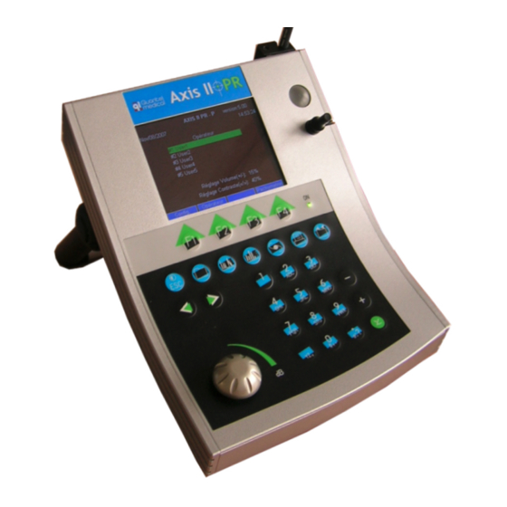
SERVICE MANUAL 2 - INSIDE ACCESS 2-1 EXTERNAL VIEW Pachymetry probe holder and test-block Color LCD screen Biometry probe test-block Biometry probe on its holder Handle Screen Function Keys Pedal key Function keys Built-in Alpha-numeric Keyboard Knob : Digital Potentiometer Rev 10-2009 P - 7... -
Page 8: How To Open The Case
SERVICE MANUAL 2 - INSIDE ACCESS 2-2 HOW TO OPEN THE CASE - From the bottom panel, unscrew the 4 screws as shown. Axis-II Bottom view 4 screws to be removed - Put the device on the normal position and lift up the upper part of the case verticaly as shown. -
Page 9: Inside View
SERVICE MANUAL 2 - INSIDE ACCESS 2-3 INSIDE VIEW Keyboard Video interface board ribbon cable CPU board Backlight cable LCD screen Ribbon cable between the Ribbon cable between the LCD screen and the video video interface board and interface board the CPU board 2-4 HOW TO CLOSE THE CASE - Put the cover back from the top side (1) first then the other side (2). -
Page 10: 3- Board Description
SERVICE MANUAL 3 - BOARD DESCRIPTION 3-1 BLOCK-DIAGRAM Footswitch RS 232 Ports USB Ports Flash memory Hard Disk Liquid Crystal Display Microcontroller (68328) Clock : Interface Date & Patient Board Time Data Programmable Logic Device (PLD) A. D. Keyboard Converter Knob Pulser Pulser... -
Page 11: Cpu Board
SERVICE MANUAL 3 - BOARD DESCRIPTION 3-2 CPU BOARD USB #1 USB #2 Probe connector : connector Lemo / 4 pins Power RS232 ports Pedal switch Pachymetry connector probe 12 VDC Buzzer Microprocessor ACEX (EPLD) XEAX2CPUV5 Analog part (Biometry filter) Analog part Ribbon Cable (Pachymetry filter) -
Page 12: Replacing A Cpu Board
To replace the board, perform the steps above in reverse order Warning: the faulty board must be returned to QUANTEL MEDICAL as a whole without unmounting or opening any component. Failure to comply will void the equipment warranty. -
Page 13: Replacing A Video Interface Board
Remove the board To replace the board, perform the steps above in reverse order Warning: the faulty board must be returned to QUANTEL MEDICAL as a whole without unmounting or opening any component. Failure to comply will void the equipment warranty. -
Page 14: Replacing An Lcd Screen
Warning: the faulty board must be returned to QUANTEL MEDICAL as a whole without unmounting or opening any component. Failure to comply will void the equipment warranty. -
Page 15: 4- Service Mode
AXIS-II PR - P version:5.00 Sept/03/2007 18:53:00 Information : Serial Output (1) : Not Used Quantel Medical AXIS II V5.xx User Position of marker # 1 in Contact : +0.00 mm #1 User1 Zero:16 PR Option : YES #2 User2... - Page 16 SERVICE MANUAL 4 - SERVICE MODE 4-2-1 Field “ZERO” and Position of Marker #1 The default value of this field is “16” and is given by the manufacturer of the biometry probe. This value can be different with another manufacturer and it depends on the size of the probe tip.
- Page 17 03/09/07 It defines the sharpness of the retinal Information : peaks in order to freeze the A-scan Quantel Medical AXIS II Vx.00 when the probe direction is in the Zero:16 PR Option : YES visual axis, reaching the macula area.
- Page 18 4-2-4 Field “NOISE”: Setting procedure In USER Setup, select Display Serial Number : xxxx-xxxx ID:xxxx 03/09/07 mode D1. Information : Quantel Medical AXIS II Vx.00 Zero:16 PR Option : YES Noise level: Retina Slope Test : 6 D2 / Low Dyn (dB) : 20...
-
Page 19: Activating The Post-Refractive Feature
Serial Number : xxxx-xxxx ID:xxxx 03/09/07 (when “PR Option: Yes” is present) or Information : desactivated (no “PR option” is displayed). Quantel Medical AXIS II Vx.00 Zero:16 PR Option : YES To activate it: from the hidden screen, Retina Slope Test : 6 D2 / Low Dyn (dB) : 20 position the cursor on “ZERO”, press “F1”,... -
Page 20: 5- Probe Calibration
03/09/07 (Check there are no micro bubbles on the tip). Before starting the calibration, leave the probe Information : Quantel Medical AXIS II V5.xx in the water for at least one minute, to make sure its temperature stabilizes, Zero :16 PR Option : YES then press F1 to start the calibration. -
Page 21: 6- Software Upgrade
SERVICE MANUAL 6 - SOFTWARE UPGRADE 6-1 S/W VERSION COMPATIBLITY (to) UPGRADE V1.11 V2.04 V3.05 V4.04 V5.0 (from) V1.xx V2.xx V3.xx V4.xx V5.0 Note: the software version number is displayed on the main page at the top right corner. The next paragraphs detail the recommendations when upgrading to a specific version. -
Page 22: How To Install A New Software Version
SERVICE MANUAL 6 - SOFTWARE UPGRADE 6-5 HOW TO INSTALL A NEW SOFTWARE VERSION 6-5-1 Requirements The following items are required for software installation or upgrade: - RS-232 cable with a 9-pin Sub-D connector on one end and a mini DIN-6 on the other end - disk including: . - Page 23 SERVICE MANUAL 6 - SOFTWARE UPGRADE 6-5-3 Connection Rear panel of the Axis-II. Connect the RS232 cable into this port (mini DIN-6 end) RS232 Cable Connect this connector to the serial port of the unit Connect this 9 pins Sub-D connector to the serial port COM# of the Computer Note: make sure the Axis II is switched off before connecting or disconnecting any cable.
- Page 24 SERVICE MANUAL 6 - SOFTWARE UPGRADE 6-5-4 Run the install software (QUANTELPROG.EXE) When running the installshield program QUANTELPROG, the following screen will be displayed: 6-5-5 Setup the communication parameters From the above Quantelprog screen, click on “SETUP” and select the following parameters: Select the correct com port on the PC side...
- Page 25 SERVICE MANUAL 6 - SOFTWARE UPGRADE 6-5-6 Load the new software file Press this button to specify the new software file location (example : D:\AXII500.p). The following page is displayed. Check the “filename.p” location by browsing with the Select key. Press OK to validate.
- Page 26 SERVICE MANUAL 6 - SOFTWARE UPGRADE 6-5-8 Download the new software Press this button to download the new software. The following messages will be displayed : 6-5-9 Installation completion The following page is displayed when the download is completed and the software is installed.
- Page 27 SERVICE MANUAL 6 - SOFTWARE UPGRADE 6-5-10 Restore the system parameters Restore the parameters that have been saved in chapter 6-5-2, including: - general setup parameters - hidden page parameters - user setup parameters with the IOL references for each user Note: Remember to perform a calibration.
-
Page 28: 7- Troubleshooting
General setup page of Axis II and that these communication values are also set on the Visuscan/EDR setup screen. 3. Press any key to exit then print again. If the problem persists, contact immediately your local distributor or Quantel Medical. 7-2 ERROR MESSAGE: “NO PRINTER SELECTED” When: During printing. -
Page 29: Appendix A- Evolution Of The Configuration
SERVICE MANUAL APPENDIX - A (1/8) EVOLUTION OF THE CONFIGURATION (FROM V1.X TO V5.0) AXIS II Software V 1.xx V 2.x V 3.x V 4.0-4.02 V 4.04 V 5.0 version Configuration USB ports for Same USB ports USB ports for USB Keyboard + as V4,04 + H/W config... - Page 30 SERVICE MANUAL APPENDIX - A (2/8) The purpose of this section is to detail the evolution between the different software versions of the Axis II : 1.xx, 2.xx, 3.xx and 4.xx in terms of hardware. The screen display of versions 1.xx and 2.xx is black and white. The video board and the LCD screen are identical for both versions of CPU board.
- Page 31 SERVICE MANUAL APPENDIX - A (3/8) LCD screens Two generations of black and white LCD screen have been installed on the Axis II. They are compatible with the Axis II software versions 1.xx and 2.xx. To differentiate the two screens, you must check the small components located on the LCD screen board as below : LCD Screen Second generation : No Capacitor LCD Screen First Generation : Capacitors...
- Page 32 SERVICE MANUAL APPENDIX - A (4/8) Video interface board To upgrade a Video Interface Board First Generation into Second Generation, follow the procedure as below: Cut the two tracks located between : - pin 11 of connector J1 and pin 3 of the IC2 circuit - pin 12 of connector J1 and pin 4 of the IC2 circuit Reverse the signal of the contrast by connecting a wire between : - pin 11 of connector J1 and pin 4 of the IC2 circuit...
- Page 33 «bio100.pof» for the V2 CPU board (that controls B&W screens). Installation is performed by using «quartus.exe». With new CPU boards (for S/W versions 4.xx and 5.xx, the Max version is included in the software version. Note: No modification should be made to this Quantel Medical. Rev 10-2009 P - 33...
- Page 34 SERVICE MANUAL APPENDIX - A (6/8) How to differentiate CPU boards (V2.xx vs. V3.xx) In order to differentiate the CPU boards for software versions 2.xx and 3.xx, the jumper on the soldering side is set as follows: V 2.xx Jumper: V 3.xx Jumper: CPU board (for software version V4.xx) This board is very similar to the one for software version 5.00 except that it does not...
- Page 35 SERVICE MANUAL APPENDIX - A (7/8) How to differentiate video interface boards (V3 vs. V5) XEAX2PCBVIDEOV5 XEAX2PCBVIDEOV3 IC2 present IC2 replaced by a jumper Rev 10-2009 P - 35...
- Page 36 SERVICE MANUAL APPENDIX - A (8/8) Internal configuration evolution Interface board Interface board AxisII S/W Interface board XEAX2PCBVIDEOV5 CPU board XEAX2PCBVIDEOV3 Characteristics µprocessor RAM size version XEAX2PCBVIDEO (IC2 replaced by (IC2 present) jumper) XEAX2CPU .1 potentiometer V1.xx MAX version: (adjustment of "bio100.pof"...
-
Page 37: Validation
SERVICE MANUAL VALIDATION Software Version 5.xx Publishing Date October 2009 Revision Date October 21th 2009 Written by R. DION Checked by C. CHABRIER Validated by P. QUERO Rev 10-2009 P - 37...
Need help?
Do you have a question about the Axis II PR and is the answer not in the manual?
Questions and answers
Buenas tardes, cuando tenemos una catarata hipermadura y no conseguimos medir la Al **** este biometro, hay alguna opción para una mayor penetración en los medios? .gracias
The Quantel Medical Axis II PR biometer can achieve greater penetration in cases of hypermature cataracts by using the "Low Dyn (dB): 20" setting during the Retina Slope Test. This lower dynamic range helps improve signal detection in dense cataracts, making axial length measurements more effective.
This answer is automatically generated