Table of Contents
Advertisement
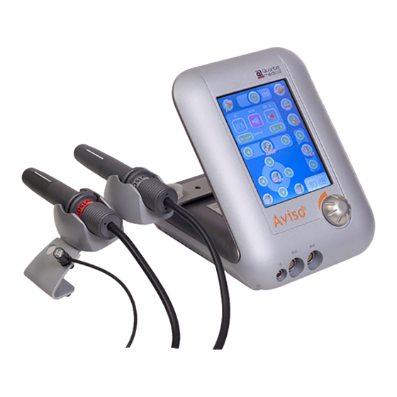
OPHTHALMIC ECHOGRAPH
BIOMETRY AND IOL CALCULATION
SERVICE MANUAL
XE AVI MT AN
APRIL 2009
QUANTEL MEDICAL SAS
Head Office : 21, rue Newton, Z.I. du BREZET
63039 - Clermont-Ferrand cedex 2 - FRANCE
Tel: +33 (0) 473 745 745 - Fax: +33 (0) 473 745 700
E-mail:
contact@quantel-medical.fr
Web site:
www.quantel-medical.fr
Advertisement
Table of Contents

Related Manuals for Quantel Medical Aviso


Summary of Contents for Quantel Medical Aviso
- Page 1 SERVICE MANUAL XE AVI MT AN APRIL 2009 QUANTEL MEDICAL SAS Head Office : 21, rue Newton, Z.I. du BREZET 63039 - Clermont-Ferrand cedex 2 - FRANCE Tel: +33 (0) 473 745 745 - Fax: +33 (0) 473 745 700 E-mail: contact@quantel-medical.fr...
-
Page 3: Warnings
Defective CPU Board will be returned to Quantel Medical as a whole for replacement. Any faulty component will be replaced by a strictly identical component. - Quantel Medical shall not be liable for any intervention or attempt to repair the "CPU Board" should any incident or breakdown occur. -
Page 4: Table Of Contents
SERVICE MANUAL TABLE OF CONTENTS Page 04-09 Warnings Table of contents 1- MAIN UNIT AND ACCESSORIES 2- TECHNICAL SPECIFICATIONS 2-1 Classification 2-2 Electrical requirements 2-3 Compliance 2-4 Dimensions 2-5 Environmental conditions 2-6 Minimum requirement of computer 3- OVERALL BLOCK DIAGRAM 4- DISASSEMBLING 4-1 Cover removal 4-2 Device subsystem... -
Page 5: 1- Main Unit And Accessories
XE PRB 25 LIN PC 25 MHz Linear probe XE PRB 50 LIN PC2 50 MHz Linear probe 10 movable windows (with film) for XE PRB FEN2 LIN50 probe XE AAA PED Footswitch XE AVI VALISE Carrying case for Aviso Rev 04-2009... -
Page 6: 2- Technical Specifications
SERVICE MANUAL 2- TECHNICAL SPECIFICATIONS 2-1 CLASSIFICATION The system is intended for continuous operation and has the following classification: - Electric security class: EN 60 601-1 Standard - Protective class: - Type: 2-2 ELECTRICAL REQUIREMENTS Power supply: 100 to 240 V~ ±10% single-phased Frequency: 50 / 60 Hz Note: “~”... -
Page 7: Minimum Requirement Of Computer
SERVICE MANUAL 2- TECHNICAL SPECIFICATIONS 2-6 MINIMUM REQUIREMENT OF COMPUTER Processor Intel Pentium IV 2 GHz or higher ® ® Intel Pentium Centrino 1,6 GHz or higher ® ® ® Athlon 2 GHz or higher ® ® Screen format 16/9 or 16/10 format - 15.4”... -
Page 8: 3- Overall Block Diagram
SERVICE MANUAL 3- OVERALL BLOCK DIAGRAM Rev 04-2009... -
Page 9: 4- Disassembling
SERVICE MANUAL 4- DISASSEMBLING 4-1 COVER REMOVAL BEFORE ANY INTERVENTION on the AVISO unplug the mains cord at its back. Remove all connections. To remove the cover: - Remove the power button (front face) and the button allows the fixing of the probe holder (rear face) - Unscrew the 8 screws on the bottom face (see below). -
Page 10: Device Subsystem
SERVICE MANUAL 4- DISASSEMBLING 4-2 DEVICE SUBSYSTEM 4-2-1 TOUCH SCREEN BLOCK AND CPU BOARD WARNING : The touch screen is very fragile. Unscrew the 3 screws (see below). 3 screws (M3x6) Unplug the 4 cables. Rev 04-2009... -
Page 11: Interface Board
SERVICE MANUAL 4- DISASSEMBLING The CPU board is situated on the back screen chassis. Unscrew the 4 screws. 4 screws (M3x6) 4-2-2 INTERFACE BOARD Remove the 2 nuts of the B-probes connectors with (for example) a flat pliers. Unscrew the 4 screws. 4 screws (M3x6) 2 nuts... -
Page 12: Power Supply Board
SERVICE MANUAL 4- DISASSEMBLING 4-2-3 POWER SUPPLY BOARD - Disconnect all connectors and unscrew the 2 screws on the rear face. Connectors to disconnect 2 screws (M3x6) Rev 04-2009... -
Page 13: Special Unmounting And Mounting
SERVICE MANUAL 4- DISASSEMBLING 4-3 SPECIAL UNMOUNTING AND MOUNTING 4-3-1 TOUCH SCREEN BLOCK DISASSEMBLING WARNING : The touch screen is very fragile and the replacement of any components must be done following the procedure below. Perform it in comfortable space with care to avoid any damage. Upper side Step 1 Step 3... - Page 14 SERVICE MANUAL 4- DISASSEMBLING Step 4 : Lift up lightly the right side of the metallic chassis. Pull it slightly to release the plate from the screen housing. Take care to the flat cable who get through the support. Slide it out.
-
Page 15: Touch Screen Block Assembling
SERVICE MANUAL 4- DISASSEMBLING 4-3-2 TOUCH SCREEN BLOCK ASSEMBLING The new tactile glass must be replaced with 3 new flat strip joints and one new flat joint. Green Piste verte 1. Place the 3 new flat strip sur le joints on the metalic support. Place the short strip on the down part of the metallic piece. - Page 16 SERVICE MANUAL 4- DISASSEMBLING Tighten completly the 2 screws A. Continue to slide the 4 screws without heads inside the tubes by screwing without never tight them. The pressure of these screws on the glass must be at the minima. WARNING : Never tighten hardly these screws.
-
Page 17: 5- Maintenance
It can be necessary after a transport, a screen assembly changing, a software upgrade or other wich could change the touch screen calibration. This calibration can be done only if the Aviso software on thce computer is not started or if the Aviso and the computer are not linked. -
Page 18: Fuse Replacement
• 5 x 20 mm A-PROBE CALIBRATION Biometry and ProBeam probes can be installed and used on the 3.0 Aviso software, without doing a calibration between each use of the probe. A calibration can be performed for each probe, and permits to get the correct position of the first marker in Contact. - Page 19 SERVICE MANUAL 5- MAINTENANCE If no biometry and/or ProBeam parameters have been installed, you have to: Click on the « Add » icon, Select the CD-Rom drive, Select the « .prb » file, Click on « Open », the probe is added in the list. If the biometry and/or ProBeam parameters are installed, you have just to perform the calibration of each probe: Select the probe to calibrate in the list, (the selected probe is...
- Page 20 SERVICE MANUAL 5- MAINTENANCE Put a drop of water on the tip of the probe, and put the tip of the probe on the test block. You have to measure 10.00mm on the test block in the « Best » field, which corresponds to the minimum measured value: when the probe is well perpendicular and in the centre of the test block.
-
Page 21: 6- Software
- Probes folder, which contains the probe parameters. These ones are located: If the Operating System is Windows XP or Vista 32 bits (with the UAC ® not activated): C:\Program Files\Quantel Medical\Aviso If the Operating System is Windows Vista 32 bits (with the UAC ® activated):... -
Page 22: Upgrade The 1.X Software Version Database
« C:\Program Files\Quantel Medical\Aviso » directory, even the new created physicians, patients and data (the « UAC » has to be kept un-activated, to use the Aviso software and be able to write in the « Program Files » directory). -
Page 23: Release Of The Module Software
ProBeam Icon: Note: For a new Aviso order, the new icons will be present in the Aviso software, in the Aviso module and in the CD-Rom parameter of the probe. For an upgrade of the unit (on the field), the new software will permit to... - Page 24 SERVICE MANUAL 6- SOFTWARE Installation of the upgrade software on the computer: On a computer (with Windows XP ONLY), extract the UsbProg file and run ® the Setup.exe. The following window is opened: Click on the Next button, the following window is displayed: The default folder is recommended.
- Page 25 SERVICE MANUAL 6- SOFTWARE The following window is opened: Click on the Next button to run the file installation. The following screen is displayed. Please wait until the procedure is finished. When the window Installation Complete is displayed, click on Close button to close the windows and finish the installation.
- Page 26 Medical in the Start menu. Click on this shortcut, the following window is opened. Check that the USB link is performed between the Aviso module and the computer. The Aviso module has to be started. Choose the FlashBCont102.scr script. This file is in the SciptFiles folder under C:\Program Files\Quantel Medical\USB Prog.
- Page 27 SERVICE MANUAL 6- SOFTWARE The progress state is visualized on the window. At the end of the procedure, the module restarts. You have to wait that the Prog Device and Cancel buttons are activated. So, you can close the window. Rev 04-2009...
-
Page 28: 7- Validation
SERVICE MANUAL 7- VALIDATION Version 3.xx Publication date April 2009 Revision date April 2009 Written by R. DION Checked by C. CHABRIER Validated by P. QUERO Rev 04-2009...
Need help?
Do you have a question about the Aviso and is the answer not in the manual?
Questions and answers