Table of Contents
Advertisement
Quick Links
Advertisement
Table of Contents

Related Manuals for TRI tool BOILERMASTER


Summary of Contents for TRI tool BOILERMASTER
- Page 1 Operation Manual...
- Page 2 Our products are backed by a company totally committed to service, integrity, and customer satisfaction. Tri Tool Services has developed a solid reputation as a trusted provider of dependable and cost-effective on-site service solutions including turnkey project management, machining services, and mechanized and manual code welding services using experienced and well- trained machinists and welders.
-
Page 3: Table Of Contents
TABLE OF CONTENTS ABOUT THE MANUAL SAFETY GENERAL DESCRIPTION SPECIFICATIONS MAINTENANCE SETUP OPERATION CUTTING SPEEDS AND FEEDS JAW BLOCKS AND RAMP SETS TOOL BITS TROUBLESHOOTING ACCESSORIES ILLUSTRATED PARTS BREAKDOWN... - Page 4 Other rights vary from state to state. Tool Bit Resharpening Policy Tri Tool Inc. can not resharpen badly gouged, chipped, or broken tool bits. Check the tool bits before you send them and package them well. Within two working days of receipt, the tool bits are evaluated and the customer is contacted for authorization.
-
Page 5: About The Manual
The instructions and descriptions in this manual were accurate when the manual was written. However, the information in the manual is subject to change without notice. Check for updated information before you start any job. The Tri Tool Inc. web site has the most current information. - Page 6 TRI TOOL INC. 2.2 PERSONAL PROTECTIVE EQUIPMENT • Use standard safety equipment such as: hard hats, safety shoes, safety harnesses, protective clothes, and other safety devices when appropriate. • Wear safety glasses. • Do not wear loose clothing or jewelry.
- Page 7 Model BOILERMASTER 2.5 AREA EQUIPMENT • Secure the pipe with clamps, vises, chains or straps. • Ensure that both sides of the pipe at the cut site is fully supported so that the pipe will not move after the cut is completed. Long lengths of pipe may be under load and the separation of the pipe can release pressure.
- Page 8 TRI TOOL INC. 2.7 TOOL USE • Use the right tool and tool bit for the job. Contact Tri Tool to help with your application. • Keep the tool bits fully engaged in the tool bit holders. Loose bits are sharp and can cause cuts or punctures.
-
Page 9: General Description
Model BOILERMASTER GENERAL DESCRIPTION The BOILERMASTER™ is a Pipe Beveler designed for facing, beveling and/or counterboring the ends of the pipe or tubing in preparation for welding. These machining operations may be performed either simultaneously or separately. Pipe weld end preparations that meet all existing conventional codes including the more stringent nuclear codes may be machined. -
Page 10: Specifications
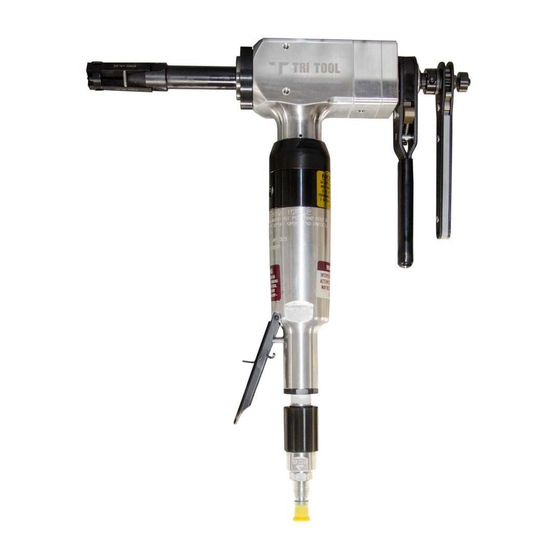
TRI TOOL INC. SPECIFICATIONS 4.1 BOILERMASTER WITH AN AIR MOTOR 16.41" (416.8 mm) 2.63" 8.72" (66.8 mm) (221.5 mm) Mandrel Cutting Head Draw Nut Handle On/Off Lever with Deadman Switch Feed Handle 19.88" (505.0 mm) Air Flow (Speed) Control Valve Figure: 1. - Page 11 Wall thickness of all standard pipe schedules (.531” [13.5 mm] maximum) in the range listed. Contact Tri Tool Inc. for procedures for heavier wall pipe. Counterboring Operation The machine will counterbore pipe and tubing with an ID range of 1.50” (38.1 mm) to 4.33”...
- Page 12 Manually actuated draw rod expands the mandrel ramps and the jaw blocks FEED Manual feed wrench is in line at the back of the machine Feed rate is .100” (2.5 mm) per revolution of the feed wrench 4.2 BOILERMASTER WITH AN ELECTRIC MOTOR Weight 18 lbs. (8.1 kg) Power Requirements 115 VAC, 28 to 60 Hz 5.25 amp...
- Page 13 Wall thickness of schedules listed, .276” (7 mm) maximum, in the range listed can be machined without limitations. Wall thicknesses greater than .276” (7 mm) require special procedures and are subject to Duty Cycle limitations to prevent motor damage. Contact Tri Tool Inc. for heavier wall procedures. Counterboring Operations The tool will counterbore pipe and tubing with an ID of 1.50”...
-
Page 14: Maintenance
Make sure that the gear box has grease. Add more if necessary. • Use a lithium based grease for gears and bearings. • The Air Supply for the BOILERMASTER with an air motor required adequate filter, regulator and lubricator (FRL). • The maximum line pressure is 90 PSI (621 kPa). - Page 15 Figure: 2. Model BOILERMASTER Sites to Clean 5.2 AIR MOTOR MAINTENANCE CAUTION: Disassembly of a power unit voids warranty, except when performed by a Tri Tool Inc. designated person. A letter of designation is required CAUTION AIR SUPPLY Make sure that the air supply flows through a filter/regulator/lubricator (FRL).
- Page 16 TRI TOOL INC. AIR MOTOR LUBRICATION If the BOILERMASTER will not be used for 24 hours or more after being run on 'wet air', squirt oil directly into the air motor inlet and run the motor for 2 to 3 seconds.
-
Page 17: Setup
6.1 PREPARE THE BOILERMASTER Select the jaw blocks for the pipe size to be machined. Refer to Section 9. Gently slide the mandrel assembly into the BOILERMASTER until it comes to a stop against the torque acceptance key. Refer to Fig. 3. - Page 18 TRI TOOL INC. The BOILERMASTER with the mandrel assembly installed may be mounted into the pipe or tube as one unit. Refer to Fig. 4. CAUTION: Install the mandrel beyond the final end preparation. This will help to avoid cutting the ramps or jaw blocks.
- Page 19 Tool Bits. The use of dull or improperly designed tool bits or tool bits not manufactured by Tri Tool Inc. may result in poor performance and may constitute abuse of the machine. This action voids the Tri Tool Inc. factory warranty.
- Page 20 TRI TOOL INC. Figure: 6. Cutting Head Insert the tool bit(s) into the slot(s) in the cutting head. Make sure the cutting edge of the tool bit(s) must be located on the radial centerline. Make sure that the tool bit(s) are not installed backwards.
-
Page 21: Operation
DANGER Figure: 7. Deadman Switch Attach the required air supply line to the BOILERMASTER™. Check that the filter/regulator/lubricator (FRL) is installed and set properly. Depress the air motor trigger. Adjust the cutting speed by rotating the flow valve at the air connection. Refer to section 8, Cutting Speeds and Feeds Rotate the feed handle clockwise to bring the tool bit(s) and pipe closer together. - Page 22 TRI TOOL INC. Figure: 8. Tool Bit with Wedge Block Figure: 9. Tool Bit with Set Screws 92-0629 Rev. 160129...
-
Page 23: Cutting Speeds And Feeds
Model BOILERMASTER CUTTING SPEEDS AND FEEDS 8.1 APPROXIMATE CUTTING SPEEDS Nominal RPM for RPM for RPM for Pipe True Diameter 200 in/min 250 in/min 300 in/min Diameter (5080 mm/min) (6350 mm/min) (7620 mm/min 1" 1.315" 33.4 mm 2" 2.375" 60.3 mm 3"... -
Page 24: Jaw Blocks And Ramp Sets
TRI TOOL INC. JAW BLOCKS AND RAMP SETS Figure: 10. Jaw Blocks and Ramp Sets Standard Jaw Block ID Mounting Block Ramp Assembly Range Height (3 Req'd) (3 Req'd) 1.250" to 1.630" 48-0964 (31.8 mm to 41.4 mm) 1.560" to 2.000"... - Page 25 Model BOILERMASTER ID Mounting Ramp and Block Combination Range 1.250" to 1.630" (31.8 mm to 41.4 mm) 1.560" to 2.000" (39.6 mm to 50.8 mm) 1.930" to 2.390" (49.0 mm to 60.7 mm) 2.320" to 2.780" (58.9 mm to 70.6 mm) 2.710"...
- Page 26 TRI TOOL INC. ID Mounting Ramp and Block Combination Range 3.090" to 3.550" (78.5 mm to 90.2 mm) 3.480" to 3.940" (88.4 mm to 100.1 mm) 3.870" to 4.330" (98.3 mm to 110.0 mm) 92-0629 Rev. 160129...
- Page 27 Model BOILERMASTER Butt Plate, Spring and Ramp for Mandrel Assembly (P/N 06-0414) ID Mounting Range Butt Plate P/N Spring P/N Ramp P/N 1.000" to 1.250" 24-1462 40-0108 48-0976 (25.4 mm to 31.8 mm) Butt Plate, Spring and Ramp for Mandrel Assembly (P/N 06-0413)
-
Page 28: Tool Bits
TRI TOOL INC. 10. TOOL BITS 10.1 TOOL BIT, BEVELING 2.63" DIA Head Kit Beveling Pipe or Tube Max Wall ID Mounting Range 37.5 Degree Material Thickness Tool Bit P/N 1.25" ID thru 2.63" OD .531" CS/SS BOILERMASTER (31.8 mm ID thru 66.8 mm OD) (13.5 mm) - Page 29 Model BOILERMASTER 10.2 TOOL BIT, FACING LAND (HEAVY DUTY) 2.63" DIA Head Kit Pipe or Tube Max Wall Facing Tool ID Mounting Range Material Thickness Bit P/N 1.25" ID thru 2.63" OD .531" CS/SS 99-5243 (31.8 mm ID thru 66.8 mm OD) (13.5 mm)
- Page 30 TRI TOOL INC. 10.3 TOOL BIT, BEVELING AND FACING 2.63" DIA Head Kit Pipe or Beveling Facing Max Wall ID Mounting Range Tube 37.5 Degree Tool Thickness Material Tool Bit P/N Bit P/N 1.25" ID thru 1.90" ID .531" CS/SS...
-
Page 31: Troubleshooting
Model BOILERMASTER 11. TROUBLESHOOTING Problem: Tool Bit Chatters The tool bit is loose or overextended. The tool bit is damaged. The tool holder is too loose in the slides. The cutting speed is too fast. The clamping pads are loose on the pipe or tube. - Page 32 TRI TOOL INC. Problem: Loss of Air Power The air supply pressure is too low. The air filter is plugged. The air line size is insufficient. The air line is too long. Problem: Loss of Hydraulic Power The hydraulic supply pressure is too low.
-
Page 33: Accessories
The following accessory is recommended for use with the BOILERMASTER and is available from TRI TOOL INC: • Portable Air Filter (P/N 75-0115 A portable Air Caddy (FRL) is required to protect the warranty on all TRI TOOL INC air driven tools. 92-0629 Rev. 160129... -
Page 34: Illustrated Parts Breakdown
TRI TOOL INC. 13. ILLUSTRATED PARTS BREAKDOWN BOILERMASTER SUB-ASSEMBLY (P/N 02-2215) Parts List, BOILERMASTER Sub-Assembly (P/N 02-2215) Item Part Description 19-0728 HOUSING, MAIN 19-0729 HOUSING, FEED 20-1025 SHAFT, MAIN 92-0629 Rev. 160129... - Page 35 Model BOILERMASTER BOILERMASTER SUB-ASSEMBLY (P/N 02-2215) cont Parts List, BOILERMASTER Sub-Assembly (P/N 02-2215) Item Part Description 27-0513 ADAPTER, FEED 28-0248 O-RING 29-0005 BEARING, BALL 29-0326 BEARING, BALL 29-0327 BEARING, BALL 29-0328 BEARING, TAPER, CONE 29-0329 BEARING, TAPER, CUP 29-0345 BEARING, BALL...
- Page 36 TRI TOOL INC. Parts List, BOILERMASTER Sub-Assembly (P/N 02-2215) Item Part Description 30-0411 RING, RETAINING, EXTERNAL 30-2358 RING, RETAINING, INTERNAL 30-2359 SHIM 31-0103 KEY, SQUARE, ROUND ENDS 31-0155 KEY, SQUARE, ROUND ENDS 32-0493 PIN, DOWEL, 1/8" DIA X .88" 32-0081 PIN, DOWEL, 3/16"...
- Page 37 Model BOILERMASTER MOTOR ASSEMBLY, AIR (P/N 57-0224) Parts List, Motor Assembly, Air (P/N 57-0224) Item Part Description 53-0046 VALVE, FLOW CONTROL 54-0126 COUPLING, MALE QD 54-0201 CAP, YELLOW 57-0223 MOTOR, INLINE AIR 92-0629 Rev. 160129...
- Page 38 TRI TOOL INC. ELECTRIC MOTOR ASSEMBLY, 220V Parts List, Electric Motor Assembly, 220V Item Part Description 58-0133 MOTOR ASSEMBLY, 220V 58-0323 MOTOR, MOD, ELECTRIC, 220V 27-0357 ADAPTER, MOTOR 39-0568 GEAR, DRIVE 29-0182 BEARING, BALL, 1/2" X 1 1/8" X 3/8"...
- Page 39 Model BOILERMASTER CUTTING HEAD KIT, 2.63" DIA (P/N 03-0047) Parts List, Cutting Head Kit, 2.63" DIA (P/N 03-0047) Item Part Description 21-0454 HEAD, 2.63" DIA 28-0249 SEAL, OIL 33-0056 SCREW, CAP, 5/16-18 X 1" 33-0500 SCREW, SET, 1/4-20 X .31"...
- Page 40 TRI TOOL INC. CUTTING HEAD KIT, 4.0" DIA (P/N 03-0048) Parts List, Cutting Head Kit, 4.00" DIA (P/N 03-0048) Item Part Description 21-0455 HEAD, 4.0" DIA 28-0249 SEAL,OIL 33-0056 SCREW, CAP, 5/16-18 X 1" 33-0517 SCREW, SET, 5/16-18 X .63"...
- Page 41 Model BOILERMASTER MANDREL ASSEMBLY (P/N 06-0415) Parts List, Mandrel Assembly (P/N 06-0415) Item Part Description 08-XXXX BLOCK, JAW 13-0424 MANDREL 23-0295 ROD, DRAW 24-1384 PLATE, BUTT 30-2365 COLLAR, SHAFT 30-2366 COLLAR, SHAFT 30-2367 RING, RETAINING, EXTERNAL 33-0490 SCREW, SET, #10-24 X .38", CUP POINT...
- Page 42 TRI TOOL INC. MANDREL ASSEMBLY (P/N 06-0414) Parts List, Mandrel Assembly (P/N 06-0414) Item Part Description 13-0426 MANDREL 23-0297 ROD, DRAW 24-1462 PLATE, BUTT 33-0489 SCREW, SET, #10-24 X .31" 40-0108 SPRING, EXTENSION 48-0976 BLOCK, RAMP NOT SHOWN 35-0523 NUT, DRAW ROD, 3/8-16...
- Page 43 Model BOILERMASTER MANDREL ASSEMBLY (P/N 06-0413) Parts List, Mandrel Assembly (P/N 06-0413) Item Part Description 13-0429 MANDREL 23-0298 ROD, DRAW 24-1463 PLATE, BUTT #1 24-1464 PLATE, BUTT #2 33-0477 SCREW, SET, #8-32 X .19 33-0478 SCREW, SET, #8-32 X .25...
- Page 44 • Disconnect power sources before servicing or moving the equipment. • Remove all loose articles of clothing and jewelry before operating the equipment. Be Safety Conscious! 3041 Sunrise Blvd. Rancho Cordova, CA 95742 (800) 345-5015 (916) 288-6100 www.tritool.com ©Copyright Tri Tool Inc. PN 81-0542 (06-14)
Need help?
Do you have a question about the BOILERMASTER and is the answer not in the manual?
Questions and answers