Download Print this page

Advertisement

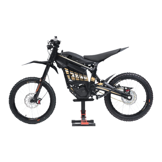
Models Covered;
TL3000 - Off Road
TL45 - On Road
Motorcycle Service
Manual
LLEXETER.CO.UK
LLEXETER LTD - UNITS 15-18 GREENDALE BUSINESS PARK - WOODBURY SALTERTON - DEVON - EX5 1EW - UNITED KINGDOM
COMPANY NO: 4940600 / VAT REGISTRATION NO: GB825156925 TEL: 01395 233128
Advertisement

loading

Summary of Contents for TALARIA STING TL3000

  • Page 1 Models Covered; TL3000 - Off Road TL45 - On Road Motorcycle Service Manual LLEXETER.CO.UK LLEXETER LTD - UNITS 15-18 GREENDALE BUSINESS PARK - WOODBURY SALTERTON - DEVON - EX5 1EW - UNITED KINGDOM COMPANY NO: 4940600 / VAT REGISTRATION NO: GB825156925 TEL: 01395 233128...
  • Page 2: Table Of Contents

    Contents; 1 General Information 2 Front wheel, Steering and Suspension 3 Rear wheel and Rear Suspension 4 Braking system 5 Electronic Power-train 6 Electric Motor and Gearbox 7 Bodywork & Chassis 8 Component Locations & Wiring Diagram All rights reserved. No parts of this publication may be reproduced, stored in a retrieval system, or transmitted in any form or by any means, electronic or mechanical photocopying, recording or otherwise,without the prior written permission of LLexeter Ltd, UK...
  • Page 3: General Information

    168kg 101kg inc. rider: wheel Model Identification (VIN Prefix): R73TL3A00M?????? Service information TL45 Sting L1e Model Code: Motor Type; Talaria 182ZW6043407NA TL3000 Sting 3000w 3700w @ 2100rpm Motor Rated Power; Motor Peak Power; Oil Grade; CL-5 Oil Type; Hypoid 85w/90 120-150ml Oil Viscosity;...
  • Page 4 Service Schedule Talaria Sting Service Schedule Interval 1 / Mileage Interval 2 Interval 3 Interval 4 Interval 5 Repeating (On & Off Road Versions) 3 Months / 250m 6 Months / 500m 12 Months / 1000m 18 Months / 1500m...
  • Page 5: Front Wheel, Steering And Suspension

    2 Front wheel, Steering and Suspension Chapter Contents 2.1 : Front Wheel removal, inspection and rebuilding 2.2 : Front Suspension, Fork removal, inspection and rebuilding 2.3 : Yoke and Steering bearings, removal, inspection and rebuilding 2.3a : Removal 2.3b : Refitting 2.1 Front Wheel - RST Fork Assembly To remove the front wheel, ensure the machine is suitably support with the wheel off the ground.
  • Page 6 2.1 Front Wheel - DNM Fork Assembly To remove the front wheel, ensure the machine is suitably support with the wheel off the ground. Do not us the side-stand as a lifting support as this may lead to injury or damage to the machine. 1.
  • Page 7 14; Upper Bearing Washer 8; Upper Yoke 15; Stem Spacers 16; Steering Crown Bolt To remove the Talaria front suspension, it is necessary to remove the Front wheel and Front brake caliper. 1. Loosen the upper yoke fork pinch bolt (M5 x...
  • Page 8 2.2 Front Suspension & Forks - DNM Forks 4. Unscrew the fork cap from the outer leg and lower the outer away from the cap. Note; the left leg does not contain any fluids 5. Using a suitable torch, apply heat to the fork cap and raise the temperature to approximately 100°c to release the thread lock and unscrew the fork cap from the compression rod.
  • Page 9 2.2 Front Suspension & Forks - DNM Forks 10. Unscrew the fork cap from the outer leg and lower the leg away from the fork cap. When refitting, tighten to 20Nm 11. Heat the fork cap to approximately 100°c to soften the thread lock and unscrew the fork cap from the damping rod.
  • Page 10 2.3 Handlebars, Yoke and Steering Bearings In order to remove the handlebars and steering yokes, it is necessary to first remove; Front wheel (Chapter 2.1) Ignition Switch (Chapter 5.6) Speedometer (Chapter 7.4) Throttle Control (Chapter 5.5) Headlamp (Chapter 7.3) Front Indicators (On-Road) (Chapter 7.3) Front and Rear Brake Levers (Chapter 4) Both the DNM Suspension and RST Suspension fitted are sold as a complete unit and if major fault or damage has occurred, replace the...
  • Page 11 2.3a Removal - RST Forks 4. Remove the steering stem crown bolt (M6 x 30mm) and remove the handlebar mount from the steering stem along with the spacer below the mount. When refitting, tighten to 8Nm 5. Loosen the top yoke fork pinch bolts for both fork legs (M5 x 16mm).
  • Page 12 Service or replace the steering bearings as required. Note the position of the upper bearing snap ring below the sealing cap. The bearing seats fitted to the chassis are recessed and do not have an exposed edge to aid removal. Correct bearing removal tools will be required.
  • Page 13 2.3a Removal - DNM Forks 5. Remove the 3 bolts (M6 x 14mm) securing the headlamp mounting bracket to the upper and lower yokes. When refitting, tighten these bolts to 8Nm Note; When refitting this mount, ensure the electrical cables to the handlebar controls are fitted through the bracket but the rear brake hose rear brake hose must be...
  • Page 14 2.3a Removal - DNM Forks Service or replace the steering bearings as required. Note the position of the upper bearing snap ring below the sealing cap. The bearing seats fitted to the chassis are recessed and do not have an exposed edge to aid removal. Correct bearing removal tools will be required.
  • Page 15: Rear Wheel And Rear Suspension

    2.3b Refitting 4. Ensure the forks are correctly aligned correctly aligned with the top of the upper yoke and tighten the pinch bolts pinch bolts to 7Nm (RST and DNM) 5. Tighten the steering stem crown bolt until the steering bearings are correctly adjusted for free turning movement, but no looseness in the bearings.
  • Page 16 3.1a Rear Wheel removal 2. Remove the wheel spindle securing nut and remove the spindle to remove the wheel from the machine. When refitting, tighten to 50Nm ± 5Nm When removing or refitting, ensure the spindle and rear wheel items are correctly located in order. 1;...
  • Page 17 3.1b Chain and Sprockets Remove the cir-clip on the outside of the front sprocket. This can be achieved with a small set of cir- clip pliers. When refitting, always fit a new cir-clip. The sprocket can now be removed from the machine. The correct sized sprocket will fit easily between the output shaft and the swing-arm.
  • Page 18 3.2 Rear Suspension 3. Remove the nut and bolt (M10 x 64mm) securing the swing-arm to the suspension linkage and remove the swing-arm from the machine. When refitting, tighten to 52Nm ± 7Nm 4. To remove the chassis bearings, first remove the spacer from the inner of the assembly and then remove the bearing to the outside of the machine.
  • Page 19: Braking System

    4 Braking System The Talaria Sting L1e uses independent hydraulic brake systems for front and rear braking. When servicing or bleeding it is essential to only use mineral oil. Do not use DOT rated oils.
  • Page 20 4.1 Front Brake System To replace the front brake disc, it is necessary to remove; Front wheel Front brake caliper 1. To replace the front brake pads, remove the 2 bolts RST Fork Assembly RST Fork Assembly (M6 x 18mm) securing the brake caliper to the fork bracket and remove the caliper.
  • Page 21 (Mineral oil only). The Talaria Sting L1e brake caliper uses a simple blanking nipple with no outlet. Caution should be taken to avoid excessive spillage or fire risk from spilt fluids.
  • Page 22 4.2 Rear Brake System Ensuring the brake fluid reservoir is topped up (Mineral oil only) follow the bleeding routine; 1. Open the bleed nipple around to allow fluid to escape. 2. Depress the front brake lever 3. Close the bleed nipple 4.
  • Page 23 (Mineral oil only). The Talaria Sting L1e brake caliper uses a simple blanking nipple with no outlet. Caution should be taken to avoid excessive spillage or fire risk from spilt fluids.
  • Page 24: Electronic Power-Train

    5.7 : DC-DC Converter 5.8 : Tilt Sensor 5.1 Motor Controller The Talaria Sting L1e utilises a proprietary motor controller developed in house by Talaria and uses a 3 phase control system to power the motor combined with a Hall effect sensor system to monitor both rotation direction and rotation speed in the motor itself.
  • Page 25 Check wiring and systems for short circuit wiring and systems for short circuit or failure Ensure battery is being charged from an Check the charger for faults official Talaria charger for the model. Check 0000E Over charge current error Charging current is too high Replace the charger and try again wiring and connections.
  • Page 26 5.2 Diagnostic Codes 1. Turn off the bike, and switch off the circuit breaker. Then, check the whether the motor phase wire terminal are loose, or broken. Check whether the motor outlet phase sequence corresponds to the U / V / W on the Check motor phase wires and Hall sensors for Controller busbar over current Controller busbar current is equal or greater than the...
  • Page 27 5.3 Motor Control Testing Set the circuit breaker to the “Off ” position and remove the battery from the machine. Remove the 3 bolts securing the Horn surround to the machine. Remove the 4 bolts (M6 x 7mm, 2 each side) securing the Motor Control Unit to the chassis and tilt the unit forwards away from the battery compartment...
  • Page 28 ≈ up to 110v dependent on load (This can be higher when being driven) 5.4 Battery and Circuit Breaker The Talaria Sting is equipped with a high voltage lithium based battery which must not be disassembled, altered or used in any way other than described in the user manual. It is possible to test the battery voltage if required but caution should be used when handling high voltage equipment.
  • Page 29 5.4 Battery and Circuit Breaker If issue is suspected the battery voltage can be checked manually. This is best performed using the ignition switch connector located in front of the circuit breaker. The loom connector block is housed in the protective shroud directly underneath the ignition switch.
  • Page 30 “On” position. Refit in the reverse of the removal procedure. 5.7 DC-DC Converter The Talaria Sting L1e utilises a DC-DC converter to provide a constant 12v supply for the ancillary components on the vehicle. This is locate beneath the battery storage, on the left of the Motor.
  • Page 31 “On” Refitting is the reverse of the removal procedure 5.8 Tilt Sensor The Talaria Sting L1e uses a microswitch tilt sensor, mounted above the motor controller, to prevent continued running in case of fall or accident.
  • Page 32 6 Motor and Gearbox Chapter Contents 6.1 Electric Motor removal and refitting 6.2 Gearbox removal and refitting 6.1 Electric Motor 1. DC-DC Converter Mount Bracket 2. Engine Cover Mount Bracket 3. Spring Washer (M6) 4. Washer (M6) 5. Bolt (M6 x 25mm) 6.
  • Page 33 6.1 Electric Motor 3. Remove the gearbox oil drain bolt (M16 x 12mm) and drain the gearbox oil. When refitting, tighten to 50Nm and always replace the sealing washer. 4. Disconnect the motor Hall sensor cable from the main wiring harness. For testing, using a suitable Ohmmeter set to the 200KΩ...
  • Page 34 6.1 Electric Motor 6. Remove the DC-DC unit, unscrew the 2 bolts (M6 x 11mm) securing it to the Motor mount and disconnect the gearbox breather at the rear of the gearbox assembly. When refitting, tighten to 7Nm 7. On the left side of the motor, remove the mounting bolts (M8 x 75mm, 51mm spacer &...
  • Page 35 6.2 Gearbox To service or repair the gearbox assembly, first remove the Motor and Gearbox assembly (Chapter 6.1). 1. Dust Cover 2. Oil Seal (20mm x 35mm x 7mm) 3. Gearbox Left Casing 4. Locating Dowell 5. Bearing (6004RZ) 6. Bearing (6005RZ) 7.
  • Page 36 6.2 Gearbox 5. Remove the intermediate gear shaft from the assembly. If necessary, replace the bearings on the output shaft and intermediate gear shaft. 6. Remove the 6 bolts (M6 x 25mm) securing the gearbox housing to the motor assembly. When refitting, tighten these bolts to 12Nm 7.
  • Page 37: Bodywork & Chassis

    Remove the battery cover from the machine. Refitting is the reverse of the removal procedure. 7.2 Rear Fairings and Saddle The Talaria Sting rear fairing and saddle unit is designed to be removed as a complete assembly for repair or replacement. Before removal, disconnect and remove the battery pack from the machine.
  • Page 38 7.2 Rear Fairings and Saddle - TL3000 Off Road To remove the swingarm mudguard and chain guard, remove the bolts (M6 x 14mm) securing them to the assembly and remove from the machine. When refitting, tighten these bolts to 5Nm 1.
  • Page 39 7.2 Rear Fairings and Saddle - TL3000 Off Road 5. If replacement is required, remove the 2 screws securing the seat rear fairing panel to the seat unit and remove the panel. 6. Remove the rear fairing assembly front cowling by releasing it from the seat lock assembly and sliding forwards away from the subframe.
  • Page 40 7.2 Rear Fairings and Saddle - TL45 On Road 3. Disconnect the rear lighting cables from the main wiring harness, located above the battery compartment to the left of the machine. 4. Remove the 2 bolts (M6 x 10mm) from the fairing panel followed by the 4 bolts (M8 x 20mm) securing the assembly to the chassis.
  • Page 41 7.2 Rear Fairings and Saddle - TL45 On Road 8. To separate the rear panel from the subframe, first remove the 2 screws securing the pieces together. Note the routing of the rear lighting wiring 9. Turn the unit over and remove the 2 bolts (M6 x 14mm) securing the panel to the subframe and separate the pieces.
  • Page 42 7.3a Headlamp - TL3000 2. Remove the 2 bolts (M5 x 12mm) securing the headlamp to the mounting bracket and remove the headlamp. When refitting, tighten to 8Nm 7.3a Headlamp - TL45 To remove the Headlamp it is necessary to remove the ignition switch (Chapter 7.1) 1.
  • Page 43 7.3d Indicator Relay To access the indicator relay, it is necessary to remove the Belly-pan. Remove the 2 front bolts (M6 x 10mm) 2 front bolts (M6 x 10mm) and 2 rear bolts + nuts (M6 x 20mm) securing the belly-pan and remove.
  • Page 44 7.3e Brake Light and Switches To replace the front or rear brake light switches, first disconnect the switch from the main wiring loom. TL3000 Off Road - The switches are connected below the ignition switch. (Chapter 5.6 for removal) TL45 On Road - The switches are connected below the speedometer.
  • Page 45 7.4 Speedometer - TL3000 Off Road To remove the speedometer form the machine, it is necessary to remove the Ignition Switch (Chapter 5.6). 1. Disconnect the speedometer from the main wiring harness. 2. Remove the pinch bolt from the speedometer control panel and open the hinged clamp to remove from the handlebars.
  • Page 46 When refitting, tighten to 5Nm 7.6 Side-stand Switch The Talaria Sting utilises a magnetic switch to activate the side-stand safety features. To test or disconnect the switch, it is necessary to remove the Belly-pan.
  • Page 47: Component Locations & Wiring Diagram

    9 Component Locations and Wiring Diagram Chapter Contents 9.1 Component Locations 9.2 Wiring Diagram 9.1 Component Locations 1. Battery 2. Battery connector 3. Ignition Switch 4. Rear lighting connector 5. Motor Controller 6. Indicator Relay (On-Road) 7. DC-DC Converter 8. Motor & Gearbox 9.
  • Page 48 9.2 Wiring Diagram - TL45 On Road Left Handlebar Switch “Eco” Button Left Indicator Right Indicator Horn Button Indicator Black Relay Brake Switches Sidestand Switch Grey Yellow/Blue Throttle Control Green/Yellow Front Right Indicator Rear Right Indicator Number Plate & Front Headlamp Rear Light Front Left Indicator Brake Light...
  • Page 49 9.2 Wiring Diagram - TL3000 Off Road Brake Switches Sidestand Switch Yellow/Blue Throttle Control Green/Yellow Rear Lig ht Red/Black Ignition Switch +12v Gnd Signal Yellow Purple Blue Purple/Black Brown Motor Control Unit Red/Green LLEXETER LTS - UNITS 15-18 GREENDALE BUSINESS PARK - WOODBURY SALTERTON - DEVON - EX5 1EW - UNITED KINGDOM Edited and compiled by Colin Price Feb 2022 COMPANY NO: 4940600 / VAT REGISTRATION NO: GB825156925 TEL: 0844 567 8887 - FAX: 0844 567 0584...
  • Page 50 m o t o r c yc l e s & s c o o t e r s Llexeter Ltd is registered in England and Wales with company registration number 4940600 Address: Units 15-18, Greendale Business Park, Woodbury Salterton, Devon, EX5 1EW TEL: 0844 567 8887 **1 FAX: 0844 567 0584 **1 Calls cost 7p per minute plus your phone company’s access charge.

This manual is also suitable for:

Sting tl45