Table of Contents
Advertisement
Quick Links
KA01134D/06/EN/01.13
71216155
Products
Brief Operating Instructions
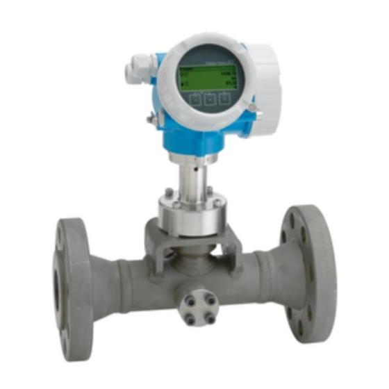
Proline Prowirl C 200
Vortex flowmeter
These Instructions are Brief Operating Instructions; they do not
replace the Operating Instructions included in the scope of
supply.
For detailed information, refer to the Operating Instructions
and other documentation on the CD-ROM provided or visit
"www.endress.com/deviceviewer".
Solutions
Services
Advertisement
Table of Contents

Related Manuals for Endress+Hauser Proline Prowirl C 200


Summary of Contents for Endress+Hauser Proline Prowirl C 200
- Page 1 Solutions Services KA01134D/06/EN/01.13 71216155 Brief Operating Instructions Proline Prowirl C 200 Vortex flowmeter These Instructions are Brief Operating Instructions; they do not replace the Operating Instructions included in the scope of supply. For detailed information, refer to the Operating Instructions and other documentation on the CD-ROM provided or visit "www.endress.com/deviceviewer".
-
Page 2: Table Of Contents
Table of contents Proline Prowirl C 200 Table of contents Document information ........... . . 3 Symbols used . -
Page 3: Document Information
Proline Prowirl C 200 Document information Document information Symbols used 1.1.1 Safety symbols Symbol Meaning DANGER! DANGER This symbol alerts you to a dangerous situation. Failure to avoid this situation will result in serious or fatal injury. A0011189-EN WARNING! WARNING This symbol alerts you to a dangerous situation. - Page 4 Document information Proline Prowirl C 200 1.1.3 Tool symbols Symbol Meaning Flat blade screwdriver A0011220 Allen key A0011221 Open-ended wrench A0011222 1.1.4 Symbols for certain types of information Symbol Meaning Allowed Indicates procedures, processes or actions that are allowed. A0011182 Preferred Indicates procedures, processes or actions that are preferred.
-
Page 5: Basic Safety Instructions
Proline Prowirl C 200 Basic safety instructions Symbol Meaning A, B, C, ... Views A-A, B-B, C-C, ... Sections Flow direction A0013441 Hazardous area Indicates a hazardous area. A0011187 Safe area (non-hazardous area) Indicates a non-hazardous area. A0011188 Basic safety instructions... -
Page 6: Workplace Safety
Verification for borderline cases: ‣ For special fluids and fluids for cleaning, Endress+Hauser is glad to provide assistance in verifying the corrosion resistance of fluid-wetted materials, but does not accept any warranty or liability as minute changes in the temperature, concentration or level of contamination in the process can alter the corrosion resistance properties. -
Page 7: Product Description
Proline Prowirl C 200 Product description Product description Product design A0020649 1 Important components of a measuring device Electronics compartment cover Display module Main electronics module Cable glands Transmitter housing (incl. HistoROM) I/O electronics module Terminals (spring loaded terminals, pluggable) -
Page 8: Incoming Acceptance And Product Identification
Incoming acceptance and product identification Proline Prowirl C 200 Incoming acceptance and product identification Incoming acceptance A0015502 A0013843 A0013695 A0015502 A0013698 A0015502 A0013699 Endress+Hauser... -
Page 9: Product Identification
Proline Prowirl C 200 Incoming acceptance and product identification A0015502 A0013697 If one of the conditions is not satisfied, contact your Endress+Hauser Sales Center. Product identification The following options are available for identification of the measuring device: • Nameplate specifications •... -
Page 10: Storage And Transport
Storage and transport Proline Prowirl C 200 Storage and transport Storage conditions Observe the following notes for storage: • Store in original packaging. • Do not remove protective covers or protective caps installed on process connections. • Protect from direct sunlight. - Page 11 Proline Prowirl C 200 Storage and transport A0015604 A0015605 Endress+Hauser...
-
Page 12: Installation
Installation Proline Prowirl C 200 Installation Installation conditions No special measures such as supports are necessary. External forces are absorbed by the construction of the device. 6.1.1 Mounting position Mounting location A0015543 Orientation Vortex meters require a fully developed flow profile as a prerequisite for correct volume flow measurement. - Page 13 Proline Prowirl C 200 Installation Orientation Compact version Remote version 4) 5) Horizontal orientation, transmitter head down A0015590 Horizontal orientation, transmitter head at side A0015592 In the case of liquids, there should be upward flow in vertical pipes to avoid partial pipe filling (Fig. A).
- Page 14 Installation Proline Prowirl C 200 Rotating the electronics housing and the display The electronics housing can be rotated continuously by 360° on the housing support. The display unit can be rotated in 45° stages. This means you can read the display comfortably from all directions.
- Page 15 Proline Prowirl C 200 Installation For the dimensions and installation lengths of the device, see the "Technical Information" document, "Mechanical construction" section 6.1.2 Requirements from environment and process Ambient temperature range Compact version Measuring device Non-Ex: –40 to +80 °C (–40 to +176 °F) Ex i: –40 to +70 °C (–40 to +158 °F)
- Page 16 Installation Proline Prowirl C 200 Thermal insulation For optimum temperature measurement and mass calculation, heat transfer at the sensor must be avoided for some fluids. This can be ensured by installing thermal insulation. A wide range of materials can be used to provide the required thermal insulation.
- Page 17 Proline Prowirl C 200 Installation 6.1.3 Special mounting instructions Outlet runs for pressure and temperature measuring points If pressure and temperature measuring points are installed after the device, please ensure there is a large enough distance between the device and the measuring point so there are no negative effects on vortex formation in the sensor.
-
Page 18: Mounting The Measuring Device
Installation Proline Prowirl C 200 A0019209 4 Layout for delta heat measurement of saturated steam and water Prowirl Temperature sensor Heat exchanger Heat flow Protective cover Maintain the following minimum head clearance: 222 mm (8.74 in) Mounting the measuring device 6.2.1... - Page 19 Proline Prowirl C 200 Installation 6.2.3 Mounting the measuring device WARNING Danger due to improper process sealing! ‣ Ensure that the inside diameters of the gaskets are greater than or equal to that of the process connections and piping. ‣...
- Page 20 Installation Proline Prowirl C 200 6.2.5 Mounting the transmitter of the remote version CAUTION Ambient temperature too high! Danger of electronics overheating and housing deformation. ‣ Do not exceed the permitted maximum ambient temperature of +50 °C (+122 F). ‣...
- Page 21 Proline Prowirl C 200 Installation Pipe mounting 20…70 ( 0.79 to 2.75) SW 13 A0019862 6 Engineering unit mm (in) Pipe mounting set 6.2.6 Turning the transmitter housing To provide easier access to the connection compartment or display module, the transmitter housing can be turned: max.
-
Page 22: Post-Installation Check
Installation Proline Prowirl C 200 6.2.7 Turning the display module 3 mm A0013905 Post-installation check Is the device undamaged (visual inspection)? Does the measuring device conform to the measuring point specifications? For example: • Process temperature • Process pressure (refer to the section on "Pressure-temperature ratings" in the "Technical Information"... -
Page 23: Electrical Connection
Proline Prowirl C 200 Electrical connection Electrical connection Connection conditions 7.1.1 Required tools • For cable entries: Use corresponding tools • For securing clamp: Allen key 3 mm • Wire stripper • When using stranded cables: Crimping tool for wire end ferrule •... - Page 24 Electrical connection Proline Prowirl C 200 Connecting cable for remote version Connecting cable (standard) Standard cable 4 × 2 × 0.34 mm (22 AWG) PVC cable with common shield (4 pairs, pair- stranded) Flame resistance According to DIN EN 60332-1-2...
- Page 25 Proline Prowirl C 200 Electrical connection 7.1.3 Terminal assignment Transmitter Connection versions A0020738 A0020739 Maximum number of terminals Maximum number of terminals for order code for Terminals 1 to 6: "Accessory mounted", option NA "Overvoltage Without integrated overvoltage protection protection"...
- Page 26 Electrical connection Proline Prowirl C 200 connection housing while the transmitter is connected via the connection compartment of the wall holder unit. The way the transmitter wall holder is connected depends on the measuring device approval and the version of the connecting cable used.
- Page 27 Proline Prowirl C 200 Electrical connection 7.1.4 Pin assignment, device plug Profibus PA PROFIBUS PA (device-side), M12 plug Assignment Coding Plug/ socket PROFIBUS PA + Plug Grounding PROFIBUS PA – Not assigned A0019021 7.1.5 Shielding and grounding Optimum electromagnetic compatibility (EMC) of the fieldbus system can only be guaranteed if the system components and, in particular, the lines are shielded and the shield forms as complete a cover as possible.
- Page 28 Electrical connection Proline Prowirl C 200 A0019004 Controller (e.g. PLC) Segment coupler PROFIBUS DP/PA Cable shield T-box Measuring device Local grounding Bus terminator Potential matching line NOTICE In systems without potential matching, the multiple grounding of the cable shield causes mains frequency equalizing currents! Damage to the bus cable shield.
- Page 29 Proline Prowirl C 200 Electrical connection 7.1.6 Requirements for the supply unit Supply voltage Transmitter An external power supply is required for each output. Supply voltage for a compact version without a local display Order code for "Output" Minimum Maximum...
- Page 30 Electrical connection Proline Prowirl C 200 • R ≤ (U ) :0.022 A term. min • R ≤500 Ω R [ ] U [V] A0020417 8 Load for a compact version without local operation Operating range 1.1 For order code for "Output", option A "4-20 mA HART"/option B "4-20 mA HART, pulse/ frequency/switch output"...
-
Page 31: Connecting The Measuring Device
Proline Prowirl C 200 Electrical connection Connecting the measuring device NOTICE Limitation of electrical safety due to incorrect connection! ‣ For use in potentially explosive atmospheres, observe the information in the device- specific Ex documentation. 7.2.1 Connecting the transmitter The connection of the transmitter depends on the following order codes:... - Page 32 Electrical connection Proline Prowirl C 200 Connection via device plug A0019147 ‣ Plug in the device plug and tighten firmly. 7.2.2 Connecting the remote version WARNING Risk of damaging the electronic components! ‣ Ground the remote version and in doing so connect the sensor and transmitter to the same potential equalization.
- Page 33 Proline Prowirl C 200 Electrical connection Connecting the sensor connection housing 3 mm A0020410 A0020411 Wire the connecting cable: Terminal 1 = brown cable Terminal 2 = white cable Terminal 3 = yellow cable Terminal 4 = green cable Connect the cable shield via the cable strain relief.
- Page 34 Electrical connection Proline Prowirl C 200 Connection to the wall holder of the transmitter Connecting the transmitter via plug A0020412 Connecting the transmitter via terminals 3 mm A0020404 Endress+Hauser...
- Page 35 Proline Prowirl C 200 Electrical connection TX 10 8 mm A0020405 ~15° A0020406 Endress+Hauser...
-
Page 36: Hardware Settings
Electrical connection Proline Prowirl C 200 A0020407 A0020409 Wire the connecting cable: Terminal 1 = brown cable Terminal 2 = white cable Terminal 3 = yellow cable Terminal 4 = green cable Connect the cable shield via the cable strain relief. - Page 37 Proline Prowirl C 200 Electrical connection The address must always be configured for a PROFIBUS DP/PA device. The valid address range is between 1 and 126. In a PROFIBUS DP/PA network, each address can only be assigned once. If an address is not configured correctly, the device is not recognized by the master.
-
Page 38: Ensuring The Degree Of Protection
Electrical connection Proline Prowirl C 200 The device restarts automatically and reports the current address (factory setting: 126). Set the address via the operating menu: Setup → Communication →Device address A0015903 11 Example of software addressing; switch 8 is set to the "ON" position; the address is defined in the operating menu (Setup →... -
Page 39: Operation Options
Proline Prowirl C 200 Operation options Are all the cable glands installed, firmly tightened and leak-tight? Cable run with "water trap" (→ 38) ? Depending on the device version: are all the device plugs firmly tightened (→ 31)? ... - Page 40 Operation options Proline Prowirl C 200 8.1.2 Operating philosophy The individual parts of the operating menu are assigned to certain user roles. Each user role corresponds to typical tasks within the device lifecycle. For detailed information about the operating philosophy of the instrument, refer...
-
Page 41: Access To The Operating Menu Via The Local Display
Proline Prowirl C 200 Operation options Access to the operating menu via the local display X X X X X X 19.184 mA 12.5 X X X X X X Language à 20.50 English Deutsch Español Français User ABC_ DEFG... - Page 42 Operation options Proline Prowirl C 200 8.2.1 Operational display Status area Status signals A0013956 A0013959 A0013958 A0013957 Failure Function check Out of specification Maintenance required Diagnostic behavior Locking Communication A0013961 A0013962 A0013965 A0013963 Alarm Warning Device locked Remote operation enabled...
- Page 43 Proline Prowirl C 200 Operation options Display area Icons for menus A0013974 A0013975 A0013966 A0013973 Operation Setup Diagnostics Expert Icons for submenus, wizards, parameters Lock symbols A0013967 A0013968 A0013972 A0013963 Submenu Wizard Parameters within a Parameter locked wizard 8.2.3 Editing view...
- Page 44 Operation options Proline Prowirl C 200 8.2.4 Operating elements Meaning Minus key In a menu, submenu Moves the selection bar upwards in a choose list. With a Wizard Confirms the parameter value and goes to the previous parameter. A0013969 With a text and numeric editor In the input mask, moves the selection bar to the left (backwards).
- Page 45 Proline Prowirl C 200 Operation options Meaning Minus/Enter key combination (press the keys simultaneously) Reduces the contrast (brighter setting). A0013953 Plus/Enter key combination (press and hold down the keys simultaneously) Increases the contrast (darker setting). A0013954 Minus/Plus/Enter key combination (press the keys simultaneously) For operational display Enables or disables the keypad lock.
-
Page 46: Access To The Operating Menu Via The Operating Tool
Operation options Proline Prowirl C 200 The user role with which the user is currently logged on is indicated by the Access status display parameter. Navigation path: Operation → Access status display 8.2.7 Disabling write protection via access code If the -symbol appears on the local display in front of a parameter, the parameter is write-protected by a user-specific access code and its value cannot be changed at the moment using the local display (→... - Page 47 Proline Prowirl C 200 Operation options 8.3.1 Via HART protocol A0013764 12 Options for remote operation via HART protocol Control system (e.g. PLC) Transmitter power supply unit, e.g. RN221N (with communication resistor) Connection for Commubox FXA195 and Field Communicator 475 Field Communicator 475 Computer with operating tool (e.g.
-
Page 48: System Integration
Proline Prowirl C 200 8.3.2 Via service interface (CDI) A0020545 Service interface (CDI = Endress+Hauser Common Data Interface) of the measuring device Commubox FXA291 Computer with "FieldCare" operating tool with COM DTM "CDI Communication FXA291" System integration For system integration: See Operating Instructions for the device on the CD-ROM provided. -
Page 49: Switching On The Measuring Device
Proline Prowirl C 200 Commissioning 10.2 Switching on the measuring device After a successful function check, switch on the measuring device. After a successful startup, the local display switches automatically from the startup display to the operational display. If nothing appears on the local display or a diagnostic message is displayed, refer to the device' s operating instructions which can be found on the CD-ROM supplied with the device. -
Page 50: Defining The Tag Name
Commissioning Proline Prowirl C 200 Wizard Meaning Current output 1 Configuring output 1 Pulse/frequency/switch output Configuring the selected output type Display Configuring the measured value display Output conditioning Defining the output conditioning Low flow cut off Configuring the low flow cut off 10.5... - Page 51 Proline Prowirl C 200 Commissioning Defining the access code via local display Navigate to the "Enter access code" parameter. Define a max. 4-digit numeric code as an access code. Enter the access code again to confirm the code. The -symbol appears in front of all write-protected parameters.
-
Page 52: Diagnostic Information
Diagnostic information Proline Prowirl C 200 XXXXXXXXXXXXX 3 mm A0013768 Loosen the securing clamp. Unscrew the electronics compartment cover. Pull out the display module with a gentle rotational movement. To make it easier to access the lock switch, attach the display module to the edge of the electronics compartment. - Page 53 Proline Prowirl C 200 Diagnostic information remedial measures can be called up from the diagnostic messages, and contains important information on the fault. X X X X X X X X X X X X X X 20.50 S801 Supply voltage...
- Page 56 www.addresses.endress.com...
Need help?
Do you have a question about the Proline Prowirl C 200 and is the answer not in the manual?
Questions and answers