Table of Contents
Advertisement
Quick Links
8 Duty / 1 Auto Amplifier Fault Changeover
Ver.4
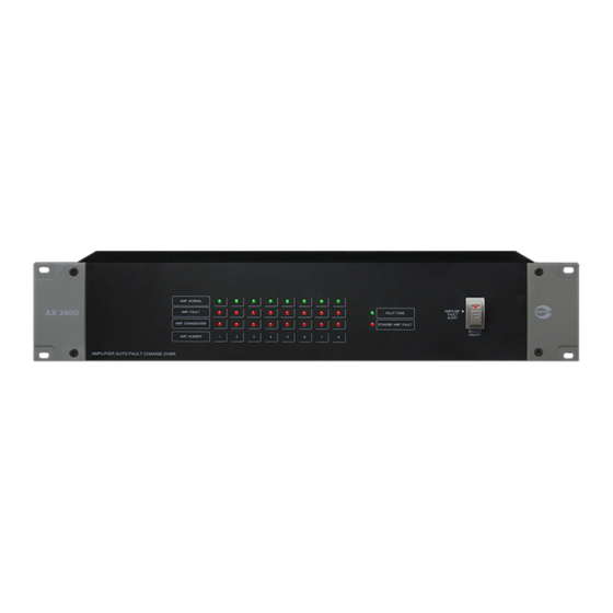
AX 3800
STANDBY AMPLIFIER CHANGEOVER
Thank you for choosing another quality product from Amperes Electronics.
AX3800 is now in version 4, which has been improved further to fulfil the demand from installers. Among the enhance-
ments made are cascade connectivity, easier termination and improved circuitries to cater for different types of amplifi-
ers, noticebly Class D power amplifiers.
AX3800 provides a medium for standby amplifier to overtake a failed duty unit automatically without human intervention
to comply with various Codes of Practices such as BS, EN or SS. By means of pilot tone injection at intervals, it ensures
power amplifiers are not loaded all the time to prevent fast aging of the power packs.
Please read through the manual to capture how AX3800 may serve your system diligently and efficiently. We are confi-
dent that you are getting a product of excellence.
View catalogue and for latest
updates
AMP1
AMP2
AMP3
AMP4
AMP5
AMP. NORMAL / FAULT
AMP. CHANGEOVER
AMP6
AMP7
AMP8
AMPSTDBY
PILOT TONE
ON/OFF
AMP FAULT ALERT
AX3800
amperes
VER 4 / 2022
Advertisement
Table of Contents

Related Manuals for Amperes AX3800


Summary of Contents for Amperes AX3800
- Page 1 Thank you for choosing another quality product from Amperes Electronics. AX3800 is now in version 4, which has been improved further to fulfil the demand from installers. Among the enhance- ments made are cascade connectivity, easier termination and improved circuitries to cater for different types of amplifi- ers, noticebly Class D power amplifiers.
-
Page 2: Parts Identification
The output will still need to be connected to its corresponding amplifier inputs. 6. STANDBY AMPLIFIER INPUT TERMINAL This terminal is to connect to standby unit’s audio input. There is no incoming terminal as per other channels. PAGE 2 AX3800 Auto Amplifier Fault Changeover... -
Page 3: Power Input Terminal
Parts Identifications ( con’t ) 7. CASCADE LINK Port to link more than one AX3800 to enable 1 standby to cater for up to 16 nos of amplifiers. Refer to section “ Cascading AX3800 ” for details. 8. POWER INPUT TERMINAL AX3800 operates on 24V DC. - Page 4 The above schematic is typical for single audio source application. For uninterrupted paging ( 2 audio sources ), connect according to setup using Matrix. Audio signal to Duty Amplifiers shall be looped., or can be fed separately from AX3800. If more than 8 duty amplifiers to be served with 1 standby, cascade AX3800 accordingly.
- Page 5 The above schematic is a typical setup for multiple input sources / uninterrupted or matrix system. It is clearly noted that each amplifier input shall connect to individual output channel from AX3800. Cascade AX3800 if one standby is to serve more than 8 power amplifiers. AX3800 Auto Amplifier Fault Changeover...
- Page 6 In this case, only connect the input at terminal Amplifier 1 and switch to LINK at all link switches. Input and output signals from AX3800 shall have unity gain. Every output to amplifiers has been buffered and therefore signal degradation due to multiple looping shall not occur from AX3800.
- Page 7 Amplifier output must be connected to IN terminals, and the outgoing to Zone Selector at OUT sections. Reversing them will cause AX3800 to treat the channel as failed. Each output of the amplifier must be terminated for monitoring. A disconnected channel shall be deemed fail.
- Page 8 Cascading AX3800 When it is required that one standby amplifier to serve more than 8 duty units, AX3800 will need to be stacked up or cascaded. The link between them has been made simpler using RJ45 connectors. To standby amplifier...
-
Page 9: Fault Detection
Pilot Tones AX3800 may work a little different from other auto standby amplifier fault changeover. It sends Pilot Tones of 20 kHz to amplifiers at intervals and shift from one channel to another to reduce loading strain. A slight delay in detection shall occur but is more beneficial in the long run, prolonging the life span of amplifiers. -
Page 10: Testing The Installation
Power up : Connect 24V DC from centralised power supply unit, ie. Amperes PS9400. If the unit is to operate using power adap- tor, use 24V DC type with 1 A rating. Usage of unregulated power supply may damage the equipment. -
Page 11: Summary Of Features
Normal ; Fault ; Changeover Buzzer with switch Changeover alert Changeover section Input and output simultaneously Dimensions ( W x H X D ) 482 x 88 x 180 mm Weight 3.15 kg AX3800 Auto Amplifier Fault Changeover PAGE 11... -
Page 12: Warranty Conditions
Information contained in this manual is subject to change without prior notice and does not represent a commitment on the part of the vendor. AMPERES ELECTRONICS SDN BHD shall not be liable for any loss or damages whatsoever arising from the use of information or any error contained in this manual.
Need help?
Do you have a question about the AX3800 and is the answer not in the manual?
Questions and answers