
Related Manuals for Avidsen YLVA 3


Summary of Contents for Avidsen YLVA 3
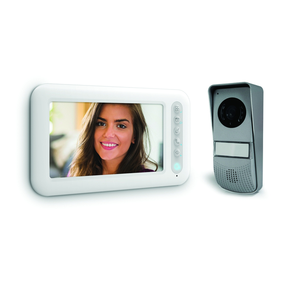
- Page 1 YLVA 3 Colour videophone 7” 2 wires ref. 112266 7” 100m www.avidsen.com...
-
Page 2: Table Of Contents
COLOUR VIDEO INTERCOM 7" CONTENTS A - SAFETY INSTRUCTIONS 1 - INTRODUCTION 2 - MAINTENANCE AND CLEANING 3 - RECYCLING B - PRODUCT DESCRIPTION 1 - KIT CONTENTS 2 - MONITOR 3 - INTERCOM PANEL 4 - WALL BRACKET 5 - MAINS ADAPTOR C - INSTALLATION 1 - INSTALLATION OF THE EXTERIOR PANEL 2 - INSTALLING THE MONITOR... - Page 3 D - USING THE PRODUCT 1 - IDENTIFY AND SPEAK TO THE VISITOR 2 - ACTIVATE THE INTERCOM PANEL FROM THE MONITOR 3 - OPENING AN ELECTRIC LOCK AND AN AUTOMATIC CONTROL SYSTEM (OPTIONAL) 4 - INTERCOM FEATURE 5 - DISPLAY OF ADDITIONAL CAMERA 6 - MONITOR SETTINGS E - TECHNICAL AND LEGAL INFORMATION 1 - TECHNICAL CHARACTERISTICS...
-
Page 5: A - Safety Instructions
COLOUR VIDEO INTERCOM 7" A - SAFETY INSTRUCTIONS 1 - INTRODUCTION • Unplug the device if it is not being used for an extended period of time. This video intercom system pairs two modules: a • Do plug device into national receiver-monitor and an easy-to-install telecommunications installations. -
Page 6: B - Product Description
COLOUR VIDEO INTERCOM 7" B - PRODUCT DESCRIPTION 1 - CONTENTS OF THE KIT Monitor Screws (2 for the monitor, 3 for the intercom panel) Intercom panel Screws for the intercom panel Monitor wall bracket Mains adapter Dowels (2 for the monitor, 3 for the intercom panel) 2 - MONITOR 4.3"... -
Page 7: Intercom Panel
COLOUR VIDEO INTERCOM 7" B - PRODUCT DESCRIPTION Loudspeaker Communication terminals for and to the Power supply terminals other parts of the installation *Subject to availability. 3 - INTERCOM PANEL Microphone Call button IR LED Loudspeaker Lens Connection terminals 4 - WALL BRACKET The monitor is designed to be fixed to the wall. -
Page 8: C - Installation
COLOUR VIDEO INTERCOM 7" C - INSTALLATION The recommended installation height for the intercom panel is about 160 cm from the ground and 150 cm from the floor for the indoor unit. 50cm 70° 160cm 150cm NOTE: For obvious safety reasons, the connections must only be made after shutting off the power supply. 1 - INTERCOM PANEL INSTALLATION The intercom panel must not be directly exposed to bad weather. -
Page 9: Installing The Monitor
COLOUR VIDEO INTERCOM 7" C - INSTALLATION Then screw the intercom panel to the hood with the screw provided. Put on the name label. 2 - INSTALLING THE MONITOR Attach the wall mount to the wall using the screws and wall plugs suited to the support (the screws and plugs supplied are suitable for solid walls). -
Page 10: Connections
COLOUR VIDEO INTERCOM 7" C - INSTALLATION 3 - CONNECTIONS • Do not increase the number of insulating screw joints or connectors on the connecting wire between the intercom panel and the monitor • Keep the connecting wire between the intercom panel and the monitor more than 50 cm away from any electromagnetic interference (230 V cable, WiFi device, microwave ovens, etc.) •... -
Page 11: Connection Between The Monitor And The Intercom Panel
COLOUR VIDEO INTERCOM 7" C - INSTALLATION The cable's length determines which cable section is to be used: Cable length Section to use 0 to 50 m 0.75 mm2 50 m to 100 m 1.5 mm2 Between the intercom panel and an electric strike plate (not included) Use a 12V/1.1A maximum electric latch with or without mechanical memory. -
Page 12: Connections
COLOUR VIDEO INTERCOM 7" C - INSTALLATION 3.2 - CONNECTIONS 3.2.1 - CONNECTIONS 2 MONITORS + 1 INTERCOM PANEL + 1 CAMERA CCTV Monitor ref. 112248 Monitor ref. 112279 Intercom panel IMPORTANT: if you have trouble opening the lock, which may be caused by a large distance between the screen and the intercom panel, for example, we recommend that you connect it to a separate power supply. -
Page 13: D - Using The Product
COLOUR VIDEO INTERCOM 7" D - USING THE PRODUCT 1 - IDENTIFY AND SPEAK TO THE VISITOR paragraph), press the button (for the lock) or The visitor presses the intercom panel button (for the automatic control system) to Nils Larsson let a visitor enter. -
Page 14: Display Of Additional Camera
COLOUR VIDEO INTERCOM 7" D - USING THE PRODUCT 5 - DISPLAY OF ADDITIONAL CAMERA If you have installed an additional camera (112248), it is possible to display it by pressing on 6 - MONITOR SETTINGS With the screen is on, press the button to display the following screen: Once in the RING sub-menu, press the... -
Page 15: E - Technical And Legal Information
COLOUR VIDEO INTERCOM 7" E - TECHNICAL AND LEGAL INFORMATION 1 - TECHNICAL CHARACTERISTICS MONITOR Ultra-flat 7" colour LCD Screen PAL/NTSC Video standard 800 x (RGB) x 480 Resolution with 230 VAC 50 Hz / 17 VDC 1.5 A Power supply mains adapter included 17 VDC 1.5 A (adapter included) Supply voltage... -
Page 16: Warranty
• If, despite the care we have taken in designing equipment designated below: our products and drafting these instructions, Ylva 3 (112266) you do encounter diffi culties when installing Complies with the RED directive and its conformity your product or you have any questions, we... - Page 18 Smarthome France 19 Avenue Marcel Dassault ZAC des Deux Lions - 37200 Tours - France...
Need help?
Do you have a question about the YLVA 3 and is the answer not in the manual?
Questions and answers