Table of Contents
Advertisement
Quick Links
Advertisement
Table of Contents

Subscribe to Our Youtube Channel
Related Manuals for Minebea Intec X3


Summary of Contents for Minebea Intec X3
- Page 1 Instrument Manual X3 Process Indicator PR 5410 Translation of the original instrument manual 9499 050 54103 Edition 12.7.0 10/10/2022 Release 4.60.xx-Exx Minebea Intec GmbH, Meiendorfer Str. 205 A, 22145 Hamburg, Germany Phone: +49.40.67960.303 Fax: +49.40.67960.383...
- Page 2 Any information in this document is subject to change without notice and does not represent a commitment on the part of Minebea Intec unless legally prescribed. This product should only be operated/installed by trained and qualified personnel. In correspondence concerning this product, the type, name, and release number/serial number as well as all license numbers relating to the product have to be cited.
-
Page 3: Table Of Contents
X3 Process Indicator PR 5410 Table of contents Table of contents Introduction............................9 Read the manual................................. 9 This is what operating instructions look like ......................9 This is what lists look like............................9 This is what menu items and softkeys look like..................... 9 This is what the safety instructions look like...................... - Page 4 X3 Process Indicator PR 5410 Table of contents Device installation..........................32 General notes ................................32 Mechanical preparation............................32 EMC-compliant installation ............................ 33 4.3.1 Connecting the screens..........................33 4.3.2 Connecting the equipotential bonding conductor................... 33 Hardware construction ............................33 4.4.1 Main board..............................33 4.4.2...
- Page 5 X3 Process Indicator PR 5410 Table of contents "Standard" application ........................119 Functions...................................119 5.1.1 General information .............................119 5.1.2 Display functions............................119 "EasyFill" application ........................120 Functions.................................. 120 6.1.1 General information ............................ 120 6.1.2 Display functions............................120 6.1.3 Filling mode ..............................120 Application menu [Start] ............................
- Page 6 X3 Process Indicator PR 5410 Table of contents 7.13 System setup................................152 7.13.1 Serial ports parameter ..........................152 7.13.2 Date & time ..............................153 7.13.3 Operating parameters..........................153 7.13.4 Printing parameter ............................153 7.13.5 Fieldbus parameter............................154 7.13.6 Network parameter ............................. 154 7.13.7...
- Page 7 X3 Process Indicator PR 5410 Table of contents 7.16.3 Selecting the load cell type ........................202 7.16.4 Calibration procedure ..........................202 7.16.5 Searching load cells ............................ 203 7.16.6 Assigning load cells ............................ 205 7.16.7 Calibrating load cells ..........................206 7.16.8 Assigning load cell names .........................
- Page 8 X3 Process Indicator PR 5410 Table of contents Production ............................269 General notes ................................. 269 Configuration using the front-panel keys ......................269 8.2.1 Configuring production mode using the front-panel keys ..............269 8.2.2 Configuring interaction mode using the front-panel keys ..............270 8.2.3...
- Page 9 X3 Process Indicator PR 5410 Table of contents Fieldbus interface ..........................314 12.1 General notes ................................314 12.2 Scale protocol (8-byte) for the "Standard" application ..................314 12.2.1 Data exchange range ..........................315 12.2.2 Reading and writing data with function numbers...................317 12.2.3...
- Page 10 X3 Process Indicator PR 5410 Table of contents 17.1 Note on using "free software" ..........................354 17.2 Decoding the serial number..........................354 17.3 General data ................................354 17.3.1 Backup for date/time ..........................354 17.3.2 Supply voltage connection 230 V AC......................354 17.3.3 Supply voltage connection 24 V DC......................354 17.4 Effect of ambient conditions ..........................355...
-
Page 11: Introduction
1 Introduction X3 Process Indicator PR 5410 Introduction Read the manual Please read this manual carefully and completely before using the product. This manual is part of the product. Keep it in a safe and easily accessible location. This is what operating instructions look like 1. -
Page 12: Hotline
X3 Process Indicator PR 5410 1 Introduction NOTICE Warning of damage to property and/or the environment. NOTICE indicates that damage to property and/or the environment may occur if appropriate safety measures are not observed. Take the corresponding safety precautions. Note: User tips, useful information, and notes. -
Page 13: Safety Instructions
If there are grounds for rejection of the goods, a claim must be filed with the carrier immediately. The Minebea Intec sales or service organization must also be notified. Before operational startup NOTICE Perform visual inspection. -
Page 14: Installation
X3 Process Indicator PR 5410 2 Safety instructions 2.4.1 Installation The device is suitable for installation in control panels or cabinets. The device has to be installed in an EMC-compliant manner, see Chapter 4.3. Component Protection class Installation Housing front... -
Page 15: Protective Ground Connection
2 Safety instructions X3 Process Indicator PR 5410 2.4.3.1 Version 230 V AC Safe interruption of both supply voltage conductors must be provided for, either by disconnecting the power connector or using a separate switch. The device is equipped with a wide range power supply and... -
Page 16: Rf Interference Suppression
General information Repairs are subject to inspection and must be carried out at Minebea Intec. In case of defect or malfunction, please contact your local Minebea Intec dealer or service center for repair. When returning the device for repair, please include a precise and complete description of the problem. -
Page 17: Replacing Fuses
2 Safety instructions X3 Process Indicator PR 5410 2.8.3 Replacing fuses 2.8.3.1 Changing fuses in an ex area WARNING Explosion possible if replacement is not done correctly! It is only permitted to replace fuses in the PR 5410 when used in the ex area, if the atmosphere is not potentially explosive. -
Page 18: Device Description
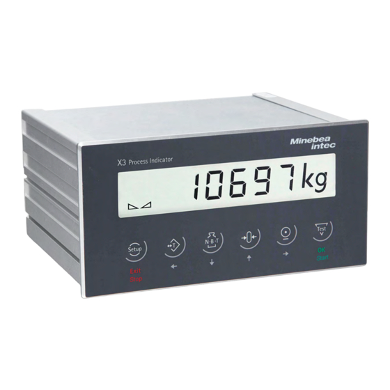
X3 Process Indicator PR 5410 3 Device description Device description General notes The instrument is equipped with a six-digit 7‑segment display and additional status displays. Local operation is possible using the 6 double function keys. The instrument contains two applications:... -
Page 19: Communication Protocols
3 Device description X3 Process Indicator PR 5410 Software configuration of the interface cards, e.g., for remote display or printer The "EasyFill" application allows for quick and reliable filling and emptying of vessels (for functional description, see Chapter 6.1). Analog test for the weighing electronics Overwrite protection using CAL switch on the main board 3.2.1... -
Page 20: Dimensions
X3 Process Indicator PR 5410 3 Device description 3.3.2 Dimensions Front view Side view all dimensions in mm all dimensions in mm Back view all dimensions in mm 3.3.3 Control panel cut-out The control panel cut-out must be made before installing the device. -
Page 21: Display And Operating Elements
3 Device description X3 Process Indicator PR 5410 Display and operating elements 3.4.1 General information The PR 5410 process indicator can only be operated using the front-panel keys or by Notebook/PC. Operation using the front-panel keys (see Chapter 7.5.2) VNC viewer (see Chapters 3.4.4.4... - Page 22 X3 Process Indicator PR 5410 3 Device description Description Weight type/plus or minus sign/standstill Bar graph Status display Weight value Symbols/mass unit Info line EN-20 Minebea Intec...
- Page 23 3 Device description X3 Process Indicator PR 5410 Weight type/plus or minus sign Description Gross weight Gross weight in NTEP or NSC mode Net weight (Net = gross - tare) Tare weight Preset tare The weight display shows the test value without mass unit.
- Page 24 X3 Process Indicator PR 5410 3 Device description 3.4.3.2 Instrument display 6‑digit weight values (digit height 18 mm) with the decimal points can be shown on the display. Description Weight type/plus or minus sign/standstill Symbols/mass unit Weight value Weight type/plus or minus sign...
-
Page 25: Operating Elements
3 Device description X3 Process Indicator PR 5410 Standstill/zero/dosing Description Weight value standstill The gross weight value is within ±¼ d of zero Batching mode: flashes when batching is "stopped"; rapid flashing indicates "error status" Symbols/mass unit Description • Range 1 •... - Page 26 X3 Process Indicator PR 5410 3 Device description Navigation/menu keys Cursor to the left Cancel entry/selection (after a confir- mation prompt) without saving the ch- Selection ange. Exit parameters/menu window. Cursor to the right Selection Function keys/softkeys Access the Setup menu.
- Page 27 3 Device description X3 Process Indicator PR 5410 Alphanumeric keypad Pressing once displays the corresponding first character, e.g.,"A", at the cursor position. After pressing twice, "B" is displayed at the cursor position and after pressing three times, "C" is displayed.
- Page 28 X3 Process Indicator PR 5410 3 Device description In the descriptions of operating sequences which entail the use of softkeys, the softkey function to be selected is shown in square brackets; the softkey symbol is not displayed; example: [Calib]. 3.4.4.3...
- Page 29 3 Device description X3 Process Indicator PR 5410 The following table shows the basic meanings of the symbols on the front-panel keys. Indicator keys Set tare Starts a printout. The current gross weight is stored in the tare memory, provided that the weight value is stable.
- Page 30 X3 Process Indicator PR 5410 3 Device description 3.4.4.5.1 Selecting parameters The selection and modification of parameters are described in the following. Press appears on the display. SEtuP 2. Press /OK. appears on the display. Cd 000 The "Cd" calibration menu flashes.
-
Page 31: Overview Of Connections
3 Device description X3 Process Indicator PR 5410 Overview of connections Minebea Intec EN-29... -
Page 32: Plug-In Cards
X3 Process Indicator PR 5410 3 Device description 3.5.1 Plug-in cards The main board can be fitted with max. 2 plug-in cards. Two cards of the same type must not be plugged into slot 1 and 2 at the same time (except for PR 5510/04). - Page 33 3 Device description X3 Process Indicator PR 5410 Product Function Position PR 1721/31 ProfiBus DP slave acc. to IEC 61158 with Slot 4 ProfiBus DP max. 12 Mbit/s For more information, see Chapter 4.6.13. PR 1721/32 InterBus-S slave with max. 500 kbit/s...
-
Page 34: Device Installation
X3 Process Indicator PR 5410 4 Device installation 4 Device installation General notes Before starting work, please read Chapter 2 and follow all instructions. WARNING Warning of hazardous area and/or personal injury All cable connections must be protected from damage. -
Page 35: Emc-Compliant Installation
4 Device installation X3 Process Indicator PR 5410 Connect the screens. Establish grounding/equipotential bonding between devices/system components. EMC-compliant installation 4.3.1 Connecting the screens The screen for the D-Sub connector must be connected as described in Chapter 4.6.1.2. The screens for the connecting cable/load cell cable must be connected to the grounding terminal on the back of the device. - Page 36 X3 Process Indicator PR 5410 4 Device installation Description Slot 4: Slot for fieldbus card Slot 1: Slot for interface card Slot 2: Slot for interface card Power supply (under the cover) Lithium battery (under the cover for the power supply)
-
Page 37: Display Board
Notebook/PC connection Remote operation of the device from a notebook/PC is possible (install VNC software version 3.3.7* on the notebook/PC). For the network address, see Chapter7.9. * Minebea Intec guarantees the functionality only if this version is used. Minebea Intec EN-35... -
Page 38: Interface
X3 Process Indicator PR 5410 4 Device installation 4.4.4 RS-232 interface The device is equipped with an integrated RS-232 interface. This interface is configurable, and can be used, for example, for data transmission to a remote display or printer. Technical data... - Page 39 4 Device installation X3 Process Indicator PR 5410 Description Data Cable gauge 1.5 mm Cable length Max.15 m Block diagram RS-232 Note: After 30 seconds without data exchange, RTS and TxD are switched off. Minebea Intec EN-37...
- Page 40 X3 Process Indicator PR 5410 4 Device installation 4.4.4.1 Connecting a YDP14IS ticket printer The YDP14IS-OCEUV ticket printer can be connected via the internal RS-232 interface or the PR 5510/02 card or the PR 5510/04 card. Configuration PR 5410 Printer configuration The printer must be set to "Line Mode"...
- Page 41 4 Device installation X3 Process Indicator PR 5410 4.4.4.2 Connecting an IS platform One IS platform scale with xBPI or SBI protocol can be connected via the internal RS-232 interface or the PR 5510/02 card or the PR 5510/04 card.
-
Page 42: Digital Inputs
X3 Process Indicator PR 5410 4 Device installation 4.4.5 Digital inputs The main board is equipped with 3 digital inputs for the process control. They are electrically isolated by optocouplers and each 2-pin potential-free. The interface can be configured by software. - Page 43 4 Device installation X3 Process Indicator PR 5410 Example: Contact input "passive" ① Digital inputs ② Supply unit U = 24 V 0.5 A Minebea Intec EN-41...
-
Page 44: Digital Outputs
X3 Process Indicator PR 5410 4 Device installation 4.4.6 Digital outputs The main board is equipped with 3 digital outputs for the process control. They are electrically isolated by optocouplers and each 2-pin potential-free. The interface can be configured by software. - Page 45 4 Device installation X3 Process Indicator PR 5410 Example: Relay control (power output) ① Digital outputs ② Inductive load for free-wheel diode ③ Supply unit U = 24 V 0.5 A The relay switches when the output is active (true).
- Page 46 X3 Process Indicator PR 5410 4 Device installation Example: Voltage output ① Digital outputs ② The load resistance must be 2.2/1 kΩ. ③ Supply unit U = 24 V 0.5 A When the output is active (true), the output voltage drops from U...
-
Page 47: Connecting Analog Load Cells And Platforms
Load cells or analog platforms (e.g. from the CAPP series) can be connected. The supply voltage is protected against short circuit and overload. Note: The colors listed here apply for the Minebea Intec load cell and connection cables of type "PR …" Color code... -
Page 48: Connecting A Load Cell With A 4-Wire Cable
X3 Process Indicator PR 5410 4 Device installation 4.5.2 Connecting a load cell with a 4-wire cable The following links between the terminal contacts are provided: ① from Sense S+ to Supply V+ ② from Sense S- to Supply V-... -
Page 49: Connecting A Load Cell With A 6-Wire Cable
4 Device installation X3 Process Indicator PR 5410 4.5.3 Connecting a load cell with a 6-wire cable Terminal Connection/color code Description + Meas./gn + Measuring voltage (load cell output) - Meas./gy - Measuring voltage (load cell output) + Sense/wh + Sense voltage... -
Page 50: Connecting Between 2 And8 Load Cells (650 Ω) Using A 6-Wire Connection Cable
X3 Process Indicator PR 5410 4 Device installation 4.5.4 Connecting between 2 and8 load cells (650 Ω) using a 6-wire connection cable Connections are made via cable junction box PR 6130/.. using connection cable PR 6135/.. or PR 6136/.. -
Page 51: Connecting Load Cells Of Type Series Pr 6221
4 Device installation X3 Process Indicator PR 5410 Connection example 4.5.5 Connecting load cells of type series PR 6221 See installation manuals of PR 6221 and PR 6021/08, ../18, ../68S. 4.5.6 Testing the measuring circuit A simple test with the load cells connected can be carried out with a multimeter. - Page 52 X3 Process Indicator PR 5410 4 Device installation Measuring voltage 0–12 mV = @ LC with 1.0 mV/V 0–24 mV = @ LC with 2.0 mV/V EN-50 Minebea Intec...
-
Page 53: External Supply To Load Cells
4 Device installation X3 Process Indicator PR 5410 4.5.7 External supply to load cells If the total resistance of the load cells is ≤75 Ω (e.g., more than 4 load cells with 350 Ω), an external load cell supply is required. In this case, the internal supply is replaced by a potential-free external supply. -
Page 54: Connection To Relay Pr 1626/6X
X3 Process Indicator PR 5410 4 Device installation 4.5.8 Connection to relay PR 1626/6x The connection is made via the connecting cable PR 6135/.. . The internal load cell power supply (V+, V-) of the PR 5410 must not be connected. - Page 55 4 Device installation X3 Process Indicator PR 5410 Connection example ① Ex-zone ② no Ex-zone (secure area) Minebea Intec EN-53...
-
Page 56: Connecting An Analog Weighing Platform (Cap
X3 Process Indicator PR 5410 4 Device installation ③ Screen ④ Cable junction box ⑤ External power supply SELV U = 24 V ⑥ Indicator ⑦ Equipotential bonding conductor NOTICE Metrological problems may occur. Make sure there is equipotential bonding between PR 1626/6x and PR 5410. - Page 57 4 Device installation X3 Process Indicator PR 5410 Example: Platform with 4-wire connection The following links between the terminal contacts are provided: ① from Sense S+ to Supply V+ ② from Sense S- to Supply V- Minebea Intec EN-55...
- Page 58 X3 Process Indicator PR 5410 4 Device installation Example: Platform with 6-wire connection EN-56 Minebea Intec...
-
Page 59: Accessories
4 Device installation X3 Process Indicator PR 5410 Accessories 4.6.1 General information The main board has three additional function-specific slots. These slots can accommodate the following cards: "Slot 1" and "slot 2": PR 5510/02 (see Chapter 4.6.2), PR 5510/04 (see Chapter 4.6.3), PR 5510/05 (see Chapter 4.6.4), PR 5510/07 (see Chapter 4.6.6), PR 5510/12 (see... - Page 60 X3 Process Indicator PR 5410 4 Device installation Note: After installation/modification, the plug-in cards are detected automatically. The installed plug-in cards can be displayed via - [Show HW-Slots]; see Chapter 7.19.3. 4.6.1.1 Installing plug-in cards Note: The ribbon cables are plugged into the ports (slot 1…2, 4) on the main board.
-
Page 61: 2× Rs-232-Interface
4 Device installation X3 Process Indicator PR 5410 Procedure: Open the plug housing (stop clamps). 2. Loosen and open the cable clamp (2). 3. Remove approx. 50-60 mm of insulation from the cable. 4. Cut back the cable screen (3) up to 5 mm and bend back over the cable mantel (1). - Page 62 X3 Process Indicator PR 5410 4 Device installation Specifications Description Data Connection 2× D-Sub female connector, 9-pin Number of channels 2 (RS-232 A and RS-232 B) Type RS-232, full duplex Transmission rate [Bit/s] 300…19K2 Bit/sec Data bits Input signal level Logic 1 (high) -3…-15 V...
-
Page 63: 1× Rs-232 Interface And 1× Rs-485 Interface
4 Device installation X3 Process Indicator PR 5410 Description Data Potential isolation None Cable type Twisted pair, screened (e.g. LifYCY 3×2×0.20), 1 pair of wi- res for ground (GND). Cable gauge 1.5 mm Cable length max. 15 m Block diagram RS-232 Note: For more information, see Chapter 4.4.4. - Page 64 X3 Process Indicator PR 5410 4 Device installation Specifications Description Data Connection 2× D-Sub female connector, 9-pin Number of channels 2 (RS-232 and RS-422/485) Transmission rate [Bit/s] 300, 600, 1200, 2400, 4800, <9600>, 19200 bit/sec Cable type Twisted pair, screened (e.g. LifYCY 3×2×0.20), 1 pair of wi- res for ground (GND).
- Page 65 4 Device installation X3 Process Indicator PR 5410 4.6.3.1 RS-232 channel The RS-232 interface depends on the "S101" switch settings. It can only be used as a point-to-point connection. PR 5510/04 is set up in the RS-232 channel the same as the fixed interface, but it has additional signals: DCD, RI, DTR.
- Page 66 X3 Process Indicator PR 5410 4 Device installation 4.6.3.2 RS-485 channel The RS-485/422 interface must be configured using switch "S101" after being installed on the card. The RS-485 interface can also be used as a point-to-point connection. Using RS-485 is compulsory with a multi-point connection (Tristate status).
- Page 67 4 Device installation X3 Process Indicator PR 5410 Function Settings for RS-422/485 Tx enable (unblock) OFF: RS-422 ON: RS-485 Rx enable (unblock) OFF: 4-wire ON: 2-wire Rx pull-up resistor OFF: not connected ON: (RxB 1K54 Ω +V) Rx bus termination OFF: not connected ON: (RxA 205E Ω...
- Page 68 X3 Process Indicator PR 5410 4 Device installation Switch settings Configuration ON: S3, S4, S5 - [Serial ports parameter]- […]- [Slot 1/2 RS485] OFF: S1, S2 Note: For more information on the switch settings, see Chapter 4.6.3.2. 4.6.3.2.2 RS-485 point-to-point connection (2-wire)
- Page 69 4 Device installation X3 Process Indicator PR 5410 4.6.3.2.3 Connecting an IS platform One IS platform scale with xBPI or SBI protocol can be connected via the RS-485 interface (2-wire). Switch settings PR 5410 Configuration PR 5410 ON: S1, S2, S3, S4, S5 - [Serial ports parameters]- [xBPI port]- [Slot 1/2 RS-485] OFF: …...
- Page 70 X3 Process Indicator PR 5410 4 Device installation 4.6.3.2.4 Connecting digital load cells from type Pendeo® The device can be ported to Pendeo® type digital load cells via the xBPI port and the RS-485 interface (2-wire). Connections Color code Color...
- Page 71 4 Device installation X3 Process Indicator PR 5410 Connection example PR 5410 switch settings PR 5410 configuration ON: S1, S2, S3, S4, S5 - [Serial ports parameter] - [xBPI-Port] - [Slot 1/ OFF: … 2 RS485] Minebea Intec EN-69...
-
Page 72: Canopen Interface
X3 Process Indicator PR 5410 4 Device installation Note: For further information, see the installation manuals relating to the load cells and junction boxes. 4.6.4 CANopen interface The CANopen interface card has the type designation PR 5510/05. Only one PR 5510/05 card can be plugged into "Slot 1" or "Slot 2". - Page 73 4 Device installation X3 Process Indicator PR 5410 Technical data Description Data Connexx module connecti- 1× D-Sub 9-pin plug connector, male ② Transmission rate [bit/s] 250 kBit/sec Potential isolation Bus termination Terminating resistor ③ of 120 Ω can be connected via a switch Switch in position “a”...
-
Page 74: Connexx Module
X3 Process Indicator PR 5410 4 Device installation 4.6.5 Connexx module 4.6.5.1 Technical data The Connexx module is the electronic part of a so-called "digital load cell". The analog weight data (mV/V) is digitalized using a 24-bit ΣΔ converter. A micro-controller converts the data into a CAN bus signal and transmits the processed signals via the CANopen interface PR 5410/05 to the PR 5410 for further processing. - Page 75 4 Device installation X3 Process Indicator PR 5410 LED status Color Function duration green Weight values provided Load cell recognized flashes alternately green/red Electronics are being configured. 4.6.5.2 Connection of Connexx modules Connexx modules can be connected to the device via the options card PR 5510/05 (see Chapter 4.6.4).
- Page 76 X3 Process Indicator PR 5410 4 Device installation Connection diagram D-Sub 9-pin → M12 5-pin Note: There are two types of cable that can be used to connect the PR 5510/05 option (CANopen interface in the PR 5410) to the first Connexx module.
- Page 77 4 Device installation X3 Process Indicator PR 5410 Connection example, shown as a diagram ① Potential equalization ② Terminating resistor ③ D-Sub 9-pin plug connector, male ④ D-Sub 9-pin plug connector, fe- male ⑤ Input voltage U = 24 V (only...
- Page 78 X3 Process Indicator PR 5410 4 Device installation 4.6.5.3 Connecting parts for the Connexx module To connect the Connexx module, the following connecting parts are required: Description Order no. PR 5510/05 CANopen interface for PR 5410 9405 355 10051 PR 6154/03 Connexx connecting kit for three load cells (comprising: 2×...
- Page 79 4 Device installation X3 Process Indicator PR 5410 4.6.5.4 External voltage supply specifications If more than four Connexx modules are to be connected, an external power supply must be used for the voltage supply. Ambient conditions Ambient temperature for operation -25…+70 °C...
-
Page 80: Analog Inputs And Outputs
X3 Process Indicator PR 5410 4 Device installation 4.6.6 Analog inputs and outputs The interface card has the type designation PR 5510/07. The plug-in card has one active analog output and 4 analog inputs. The analog inputs are not supported by the standard device. - Page 81 4 Device installation X3 Process Indicator PR 5410 Technical data Description Data Connection D-Sub female connector, 15-pin Output: Number 1 active current output: 0/4…20 mA (max. 24 mA), 10 V output voltage via external 500 Ω resistor Output: Function according to gross weight/net weight/display, configurable Output: Range 0/4…...
- Page 82 X3 Process Indicator PR 5410 4 Device installation Switch for analog inputs PR 5510/07 Block diagram Factory settings: Factory settings: S201 S202 Channel Current Voltage Voltage 0…+20 mA DC 0…+10 V DC 0…+5 V DC S201-1 S201-2 S201-3 S201-4 S201-5 …...
-
Page 83: Bcd Output (Open Emitter)
4 Device installation X3 Process Indicator PR 5410 4.6.7 BCD output (open emitter) This interface card has the type designation PR 5510/08. A PR 5510/08 card can be plugged into "Slot 2" only. The plug-in card is used for BCD-coded output of a 5-decade weight value. - Page 84 X3 Process Indicator PR 5410 4 Device installation Description Data Voltage drop Approx. 1.7 V Output current Max. 50 mA Enable input 5 V/24 V configurable via switch S101 @ 5 V active-high >3.1 V; active-low <1.5 V @ 24 V active-high >16 V; active-low <10 V...
- Page 85 4 Device installation X3 Process Indicator PR 5410 Switch for input PR 5510/08 block diagram Factory setting: Factory setting: S102 S101 An external power supply is required: PIN 1 (Uext), reference potential PIN 26 (GND) 4.6.7.1 Outputs The outputs for PR 5510/08 (PIN 2…24) work with a shared power supply at the collector as a reference potential and open emitter outputs.
- Page 86 X3 Process Indicator PR 5410 4 Device installation Output circuitry Voltage output ① common reference potential ② outputs ③ supply unit U = 24 V 0.5 A * The load resistance must be 2.2 kΩ/1 kΩ with 24 V/5 V.
-
Page 87: Bcd Output (Open Collector)
4 Device installation X3 Process Indicator PR 5410 4.6.7.2 Input The Enable input for PR 5510/08 (PIN 25) can control the 23 outputs as DATA_IN. As an output, data is "follow/hold/tristate" and its signal can be configured 5 V (TTL)/24 V and active-high/active-low. - Page 88 X3 Process Indicator PR 5410 4 Device installation Specifications Description Data Connection D-SUB female connector, 26-pin Output: Qty 5 digit BCD + preceding sign Input: Qty 1 bit "DATA_IN" Output level Shared emitter to ground, open collector External supply = +5 V…+24 V Voltage drop Approx.
- Page 89 4 Device installation X3 Process Indicator PR 5410 Switch for input PR 5510/09 block diagram Factory setting: Factory setting: S102 S101 An external power supply is required: PIN 1 (Uext), reference po- tential PIN 26 (GND) 4.6.8.1 Outputs The outputs for PR 5510/09 (PIN 2…24) work as a reference potential and open collectors with a shared ground.
- Page 90 X3 Process Indicator PR 5410 4 Device installation Output circuitry Voltage output ① common reference potential ② outputs ③ supply unit U = 24 V 0.5 A * The load resistance must be 2.2 kΩ/1 kΩ with 24 V/5 V.
-
Page 91: Switch Settings
4 Device installation X3 Process Indicator PR 5410 4.6.8.2 Input The Enable input for PR 5510/09 (PIN 25) can control the 23 outputs as DATA_IN. As an output, data is "follow/hold/tristate" and its signal can be configured 5 V (TTL)/24 V and active-high/active-low. -
Page 92: Output Modes
X3 Process Indicator PR 5410 4 Device installation 4.6.10 Output modes In all modes, the data is output during each internal PLC cycle. Mode 1: Continuous data output (follow), no DATA_IN Continuous output of consistent data, provided continuously without request, e.g., for remote display. -
Page 93: Opto-Decoupled Inputs And Outputs
4 Device installation X3 Process Indicator PR 5410 Mode 4: Continuous single-bit output (23xDA), DATA_IN (1xDE) Continuous output of bits, provided continuously without request (1xIN, 23xOUT, confi- gurable). The driver modules are always "enabled." PIN 25 (DATA_IN) is an input. - Page 94 X3 Process Indicator PR 5410 4 Device installation Specifications Description Data Connection D-Sub female connector, 37-pin Input: Qty Input: Voltage Low: U = 0…5 V or open High: U = 10…31 V Passive, external power supply required Input: Current <7 mA @ 24 V <3 mA @ 12 V...
- Page 95 4 Device installation X3 Process Indicator PR 5410 Description Data Potential isolation Yes, via optocoupler Cable type Screened twisted pair (e.g. LifYCY 2x2x0.20) Cable length max. 50 m screened Scope of delivery D-Sub male connector, 37-pin Incl. shielded housings PR 5510/12 block diagram...
- Page 96 X3 Process Indicator PR 5410 4 Device installation Digital inputs Channel CH3-CH6 Assignment Tare/reset tare, po- Print command, positive Not used sitive flank flank Digital outputs Channel CH7-CH12 Assignment "Dim" Weight is Output limit Output li- Gross weight Scale er- Not used Weight is <0...
- Page 97 4 Device installation X3 Process Indicator PR 5410 Output circuitry Voltage output ① output ② screen ③ supply unit U = 24 V 0.5 A * The load resistance must be 2.2 kΩ/1 kΩ with 24 V/5 V. Current output ①...
-
Page 98: Status Leds On Fieldbus Card
X3 Process Indicator PR 5410 4 Device installation 4.6.12 Status LEDs on fieldbus card Watchdog LED Frequency Color Meaning Flashing 1 Hz green Module is initialized and ready for operation. Flashing 2 Hz green Module is not initialized. Flashing 1 Hz... - Page 99 4 Device installation X3 Process Indicator PR 5410 Technical data Description Data Transfer rate 9.6 kbit/s to 12 Mbit/s, baud rate auto-detection Connection mode ProfiBus network, connections can be made/released without affecting other stations. Protocol PROFIBUS-DP-V0 SLAVE to IEC 61158 Mono or multi-master systems are supported.
- Page 100 X3 Process Indicator PR 5410 4 Device installation e.g.: D-Sub bus plug SIMATIC NET PROFIBUS FAST CONNECT Allocation of the 9-pin D-sub female connector Pin assignment Signal Color Description Housing ------------- Screen Not connected Not connected 3 -------------------- RxD/TxD-P (positive) ac-...
- Page 101 4 Device installation X3 Process Indicator PR 5410 NOTICE The ④ ④ rotary switch settings will not be used. Ensure that the three rotary switches for node address 1…99 are set to po- sition "0." Settings are defined via - [Fieldbus parameter][Profibus-DP].
- Page 102 X3 Process Indicator PR 5410 4 Device installation 4.6.13.4 Connection diagram for a master with three slaves EN-100 Minebea Intec...
-
Page 103: Interbus-S Interface
4 Device installation X3 Process Indicator PR 5410 4.6.14 InterBus-S interface The InterBus-S interface card has the type designation PR 1721/32. The interface is based on the InterBus chip technology and enables transfer rates of 500 kbit/s. The InterBus-S connection is established by the 9-pin D-Sub male connector (IN) ② and the 9-pin D-Sub female connector (OUT) ③... - Page 104 X3 Process Indicator PR 5410 4 Device installation Description Data Cable length 400 m (between two remote bus subscribers); overall length: 13 km Certificates From INTERBUS CLUB e.V.: Compatibility with InterBus standard. IEC 61158 (Parts 3 to 6), EN 50254 (DIN 19258)
- Page 105 4 Device installation X3 Process Indicator PR 5410 Allocation of the 9-pin D-sub female connector "OUT"③ ③ Pin allocation acc. to Signal Color acc. to Description DIN 41642 DIN 47100 Cable sheath pea green Special InterBus cable (certified) Housing Screen...
- Page 106 X3 Process Indicator PR 5410 4 Device installation 4.6.14.2 Selecting the status LED and transfer rate LED ⑦ lights up when the operating voltage is applied. The transfer rate is selected using the 2-pole jumper ④. 3 — 1 = 2 Mbit/s 4 —...
- Page 107 4 Device installation X3 Process Indicator PR 5410 Minebea Intec EN-105...
-
Page 108: Devicenet Interface
X3 Process Indicator PR 5410 4 Device installation 4.6.15 DeviceNet interface The DeviceNet interface card has the type designation PR 1721/34. The fieldbus card contains all functionalities to make a complete DeviceNet slave with a CAN controller and transmission speeds up to 500 kbit/s. - Page 109 4 Device installation X3 Process Indicator PR 5410 Description Data Cable type DeviceNet; color: petrol green; 2x2 twisted pair; screened Cable impedance 150 Ω Cable length Depends on cable type and transmission rate: 100 to 500 m Certificates Compatible with DeviceNet specification Vol. 1: 2.0, Vol 2: ODVA Certificate according to conformity test software version A‑12...
- Page 110 X3 Process Indicator PR 5410 4 Device installation 4.6.15.1 Controls on fieldbus card NOTICE The ③ ③ DIL switch settings will not be used. Make sure that the switches 1…8 are set to position "ON." ③ Settings are defined via - [Fieldbus parameter].
- Page 111 4 Device installation X3 Process Indicator PR 5410 4.6.15.3 Connection diagram for a master with three slaves Minebea Intec EN-109...
-
Page 112: Cc-Link Interface
X3 Process Indicator PR 5410 4 Device installation 4.6.16 CC-Link interface The CC-Link interface card has the type designation PR 1721/35. The fieldbus card contains all functions to provide a complete CC-Link slave with transfer rates up to 10 Mbps. - Page 113 4 Device installation X3 Process Indicator PR 5410 Designation Data Bus termination 110 Ω at the cable ends Bus load 100 mA Cable type 2x2 screened twisted pair Cable length 100 m @ 10 Mbps, 1200 m @ 156 kbps Certificates Type: ABS-CCL (H/W: 1.01, S/W: 2.00.05, CC-Link: 2.0)
-
Page 114: Profinet I/O Interface
X3 Process Indicator PR 5410 4 Device installation 4.6.16.1 Controls on fieldbus card NOTICE The ③ ③ rotary switch settings will not be used. Ensure that the three rotary switches (station no. and baud rate) are set to position "9."... - Page 115 4 Device installation X3 Process Indicator PR 5410 Technical data Description Data Transfer rate 10 Mbit/s and 100 Mbit/s Auto-detection (100, FullDX) Protocol ProfiNet I/O Connection mode Network Configuration XML file "GSDML-Vx.xx-Sartorius-PR5410-xxxxxx.xml" Potential isolation Cable type Twisted pairs, screened, e.g., patch cable CAT5 Autolink (stra-...
- Page 116 X3 Process Indicator PR 5410 4 Device installation Note: The ProfiNet I/O card is supported by PR 5410 firmware release 1.40 or higher. The IP address and subnet mask are set under - [Fieldbus parameters] (refer also to Chapter 7.18.5 and 12.2)
- Page 117 4 Device installation X3 Process Indicator PR 5410 4.6.17.1 LEDs in the module cover The module cover can be found at the rear of the device. LED 1 LED 2 LED 3 LED 4 No function ④ ④ No connection (HW)
-
Page 118: Ethernet/Ip Interface
X3 Process Indicator PR 5410 4 Device installation 4.6.18 EtherNet/IP interface The EtherNet/IP interface card has the type designation PR 1721/37. The fieldbus card is equipped with a standard RJ-45 socket ② for network connection. It contains powerful UDP/IP connecting circuitry with transfer rates of 10 and 100 Mbit/s. - Page 119 4 Device installation X3 Process Indicator PR 5410 Description Data Certificate EtherNet IP specification ODVA file no. 10286 Test date: 9/6/2005 Vendor ID 90 See also: www.odva.org Industry-compatible CE, UL, and cUL Note: The EtherNet/IP card is supported by PR 5410 firmware release 1.30 or higher.
- Page 120 X3 Process Indicator PR 5410 4 Device installation 4.6.18.2 LEDs in the module cover The module cover can be found at the rear of the device. LED 1 LED 2 LED 3 LED 4 ⑤ ⑤ No connection (HW) No power...
-
Page 121: "Standard" Application
5 "Standard" application X3 Process Indicator PR 5410 "Standard" application Functions 5.1.1 General information The "Standard" application supports the weighing functions of the device. Filling is not possible. 5.1.2 Display functions Display of gross, net or tare weight Tare/reset tare... -
Page 122: Easyfill" Application
X3 Process Indicator PR 5410 6 "EasyFill" application "EasyFill" application Functions 6.1.1 General information The "EasyFill" application is used for the batching of single components. The application allows for quick and reliable filling and emptying of vessels. The dosing process can be started, stopped, interrupted and restarted via the front-panel keys, VNC user interface, digital inputs, OPC/Modbus and field bus (except for CC link). - Page 123 6 "EasyFill" application X3 Process Indicator PR 5410 — Configuration — Configuration mode Configure the mode — Dosing mode Filling mode Selection: Net filling (B1), Net Discharge (B4) — Interaction mode Interaction mode Selection: Remote proc. control, VNC, Front keys —...
-
Page 124: Getting Started
X3 Process Indicator PR 5410 7 Getting started Getting started Power failure/Data backup/Restart 7.1.1 Power failure If the grid power fails, all entered configuration and calibration parameters and all the materials written on the built-in memory are saved. The clock and the calendar continue to run. -
Page 125: Restart
7 Getting started X3 Process Indicator PR 5410 With legal-for-trade applications, the CAL switch must be sealed in the closed position. Note: If the weighing electronics board has been changed after calibration or the device is not calibrated the weight value display will show "Error 15" if the CAL switch is closed. -
Page 126: Switching On The Device
X3 Process Indicator PR 5410 7 Getting started Press the following keys one after the other: appears on the display. SEtuP appears on the display. bIoS appears on the display. bIoS... follows on the display. FLASH appears on the display. -
Page 127: Setting The Date And Time
7 Getting started X3 Process Indicator PR 5410 Error message, if no sense voltage is connected, see also Error6 Chapter 16.1. Error message: if there is no communication with the xB- Error9 PI scale (see also Chapter 16.2). Error message: unable to read weight values from the ADU (analog-digital converter);... -
Page 128: Switching Off The Device
X3 Process Indicator PR 5410 7 Getting started 12. Use to make changes accordingly. 13. Press "OK." appears on the display. dt 086 14. Press "Exit" to exit the menu. Switching off the device The device is switched off/disconnected from power supply by pulling the plug. - Page 129 7 Getting started X3 Process Indicator PR 5410 — 020 ZEtStP Zerotrack interval — 021 ZEttIM Zerotrack time — 022 oVrLd Overload — 023 MIn Min. — 024 MuLrnG Multi-range mode — 025 rAnG 1 Range 1 — 026 rAnG 2 Range 2 —...
- Page 130 X3 Process Indicator PR 5410 7 Getting started — 064 tArKEY Tare key, function, disable — 065 ZErKEY Zeroset key, function, disable — 066 nbtKEY N.B.T key, disable — 067 PrtKEY Print key, disable — 068 tStKEY Test key, disable —...
- Page 131 7 Getting started X3 Process Indicator PR 5410 — 114 EW-CoM EW-Com — Port See Chapter 7.18.1. — 115 xBPI xBPI — Port See Chapter 7.18.1. — HS Hardware status — 120 Slot 1 EMPtY = empty or PR 5510 card type —...
-
Page 132: Recalibrating The Internal Weighing Point Using The Front-Panel Keys
X3 Process Indicator PR 5410 7 Getting started 7.5.2 Recalibrating the internal weighing point using the front-panel keys Note: If linearization is active (see Chapter 7.14.11), appears on the display. Error 91 Example: Max (maximum load) 2000.0 g Scale interval 0.5 g Set the dead load with empty scale. - Page 133 7 Getting started X3 Process Indicator PR 5410 The "Cd" calibration menu flashes. 8. Press OK. (full scale deflection) appears on the display. MAX.FSd 9. Press OK. appears on the display. ------.kg 10. Press to move the decimal point to the left by one decimal place.
- Page 134 X3 Process Indicator PR 5410 7 Getting started appears on the display. MVolt Continue for "dead load with empty scale": 24. Press OK. appears on the display. unLoAd 25. Empty the scale. 26. Press OK. A weight value for the dead load appears on the display.
-
Page 135: Changing The Dead Load Of The Internal Weighing Point Using The Front-Panel Keys
7 Getting started X3 Process Indicator PR 5410 Saving and exiting 38. Press "Exit." appears on the display. SAVE 39. Press OK. appears on the display. 40. Press OK. appears on the display during the save process. SAVE ... 41. Press "Exit" to exit the Setup menu. -
Page 136: Displaying The Calibration Data Of The Internal Wp Using The Front-Panel Keys
X3 Process Indicator PR 5410 7 Getting started (dead load with empty scale) appears on the display. LoAd 9. Press OK. appears on the display. unLoAd 10. Empty the scale. 11. Press OK. A weight value for the dead load appears on the display. - Page 137 7 Getting started X3 Process Indicator PR 5410 When the CAL switch is closed, appears on the display. CAL.CLS 4. Press OK. appears on the display. 5. Press appears on the display. VIEW 6. Press OK. (CAL switch open) appears on the display.
-
Page 138: Reading Out Calibration Data For Wp Dead Load And Max Using The Front-Panel Keys
X3 Process Indicator PR 5410 7 Getting started appears on the display. Cd 004 19. Press OK. appears on the display. SPAn 20. Press OK. The mV/V value for the maximum load appears on the display. 21. Press OK. appears on the display. -
Page 139: Search For Pendeo Load Cells And Set Dead Load Using The Front-Panel Keys
7 Getting started X3 Process Indicator PR 5410 appears on the display. dEAdLo 6. Press OK. appears on the display. LoAd 7. Press to select "MvoLt." 8. Press OK. The mV/V value for the dead load appears on the display. -
Page 140: Creating A Pin Code Using The Front-Panel Keys
X3 Process Indicator PR 5410 7 Getting started appears on the display. SEArCH 5. Press OK. appears on the display. 6. Press OK. A search for connected load cells is conducted and the dead load is set immediately thereafter. 7. Press "Exit" to exit the Setup menu. -
Page 141: Deleting The Pin Code Using The Front-Panel Keys
7 Getting started X3 Process Indicator PR 5410 11. Press OK. appears on the display. 12. Press OK. appears on the display. 000000 13. Press the cursor keys to enter the PIN code. 14. Press OK. If a wrong PIN code has been entered, appears on the display. -
Page 142: Entering Fieldbus Parameters Using The Front-Panel Keys
X3 Process Indicator PR 5410 7 Getting started appears on the display. 3. Press OK. appears on the display. 000000 4. Press the cursor keys to enter the PIN code. 5. Press OK to save the PIN code. 6. Press OK. - Page 143 7 Getting started X3 Process Indicator PR 5410 5. Press OK. appears on the display. Pro.nEt 6. Press OK. appears on the display. FP 097 7. Press OK. appears on the display. IP.Addr 8. Press OK. The more significant part of the address* appears on the display.
-
Page 144: Entering The Network Address Using The Front-Panel Keys
X3 Process Indicator PR 5410 7 Getting started appears on the display during the save process. SAVE ... 21. Press "Exit" to exit the Setup menu. An error message appears if the digit group for the IP address/mask is not within 0–255, or is invalid. - Page 145 7 Getting started X3 Process Indicator PR 5410 (example) appears on the display. 020.128. 11. If DHCP "oFF" is selected: Press the cursor keys to select and set the desired numbers. 12. Press OK. appears on the display. nP 082 13.
-
Page 146: Displaying The Network Address Using The Front-Panel Keys
X3 Process Indicator PR 5410 7 Getting started The more significant part of the address* (example) appears on the 255.255. display. 27. Press the cursor keys to select and set the desired numbers. 28. Once the last number is selected and set, press to set the less significant part of the mask*. -
Page 147: Displaying/Deleting Alibi Entries Using The Front-Panel Keys
7 Getting started X3 Process Indicator PR 5410 Press appears on the display. SEtuP 2. Press OK. appears on the display. Cd 000 The "Cd" calibration menu flashes. 3. Press multiple times to select "nP 080." 4. Press OK. (DHCP) appears on the display. - Page 148 X3 Process Indicator PR 5410 7 Getting started The "Cd" calibration menu flashes. 3. Press multiple times to select "AL 100." 4. Press OK. appears on the display. 5. Press OK. The sequence number of the last alibi entry appears on the display (right digit flashes).
-
Page 149: Deleting Alibi Entries
7 Getting started X3 Process Indicator PR 5410 7.6.2 Deleting alibi entries Press appears on the display. SEtuP 2. Press OK. appears on the display. Cd 000 The "Cd" calibration menu flashes. 3. Press multiple times to select "AL 100."... -
Page 150: Finding And Connecting The Device Automatically In The Network
X3 Process Indicator PR 5410 7 Getting started Example: If the search time is exceeded (because there is "no server found"), the PR 5410 is assigned to an IP address automatically (e.g. 169.254.0.123). The same applies to the notebook or PC (e.g. 169.254.0.54). -
Page 151: Resetting The Network Address
If the browser window remains empty after the minimum wait time, or if the expected device is not listed, the network ID of the local notebook/PC must be checked and changed, if necessary. Only certain Minebea Intec devices are supported by the "indicator browser"! 7.10 Resetting the network address This means "DHCP"... -
Page 152: Operation Using Vnc
X3 Process Indicator PR 5410 7 Getting started This ensures that a valid address for identification of the device in the network can be assigned to the device from a server, see also Chapter 7.18.6. Note: The last 3 bytes of the MAC ID are displayed. A label with the complete MAC ID is located on the outside of the device. -
Page 153: Operation Via A Web Browser
7 Getting started X3 Process Indicator PR 5410 NOTICE If the VNC viewer is terminated on the setup level (e.g. by closing the window or the back function in the web browser), the device reboots and the web menu is not accessible for several seconds. -
Page 154: System Setup
X3 Process Indicator PR 5410 7 Getting started The web menu is displayed. For description of the web menu see Chapter 9.2.1. NOTICE If the VNC viewer is closed on the setup level, the device reboots and the web menu is not accessible for several seconds. -
Page 155: Date & Time
7 Getting started X3 Process Indicator PR 5410 — xBPI-Port Selection: <none>, built-in RS-232 — Param Selection: Assigned to, Baudrate, Bits, Parity, Stopbits 7.13.2 Date & time — Date Date Input: yyyy, mm, dd — Time Time Input: hh, mm, ss 7.13.3... -
Page 156: Fieldbus Parameter
X3 Process Indicator PR 5410 7 Getting started 7.13.5 Fieldbus parameter — Fieldbus protocol 7.13.6 Network parameter — HW address MAC-ID, display: e.g.: 00:90:6C:31:1F:55 — Hostname Unique device name, input: 2…24 alphanumerical characters — Use DHCP Check the ☑ box to activate DHCP. - Page 157 7 Getting started X3 Process Indicator PR 5410 [by load]: 0.00001…999999 <kg>, t, lb, oz, g, — Calibrated at Display only — Sensitivity (µV/d) Display only — Test Determine test value — Exit calibration Save or discard changes due to new calibration.
- Page 158 X3 Process Indicator PR 5410 7 Getting started Input of the limit 2: In weight, unit same as Max, transition from small to medium scale interval Only for [Multiple range] or [Multi-interval]! — View (when CAL-switch is closed) — Max Display only —...
- Page 159 7 Getting started X3 Process Indicator PR 5410 max load = 5%/Max. load, 10% of max load = 10%/Max. Load — Power-On zero Initial zero point range: 2% of max load = range 2%/Max. load, 5% of max load = 5%/Max. load, 10% of max load = 10%/Max.
- Page 160 X3 Process Indicator PR 5410 7 Getting started — Set SBN The xBPI address of the interface has to be <0 >, because there is no bus operation. — Config Configuration of the xBPI scale — Type xBPI-Scale — W&M Selection legal-for-trade mode: <none>, OIML,...
- Page 161 7 Getting started X3 Process Indicator PR 5410 — Corner Platform 1, platform 2 (only shown if the correction number of load cells is = 8). O.k., when realized. — Modify May be used only for minor changes (e.g. changing the dead load). Otherwise, always use [New]! —...
- Page 162 X3 Process Indicator PR 5410 7 Getting started — Service Service function for load cells: Deactivate/ activate load cell. — LC 1…n load cell 1…n Select the faulty load cell and reset ☑ to ☐. Select the new (replaced) load cell and mark the checkbox ☑.
- Page 163 7 Getting started X3 Process Indicator PR 5410 — Number of Load cells Inteco®/..: Enter number. vessel feet — Local gravity Enter local gravity (standard: Hamburg 9.81379 m/s — Max Enter maximum load: 0.000010…<3000>…9999998 <kg>, t, lb, g, mg, oz —...
-
Page 164: Limit Parameter
X3 Process Indicator PR 5410 7 Getting started Enter the minimum load: 0 d…<50 d>…999999 d — Range mode Range selection: <Single range>, Multiple range, Multi-interval See also Chapter FEHLER andFEHLER. — Range limit 1 Inputrange limit 1: In weight, unit as for Max,... -
Page 165: Digital I/O Parameters
7 Getting started X3 Process Indicator PR 5410 — Limit 1…3 on Enter 0 – Max (maximum load); take unit from calibration. — Action Action, selection: no action, set marker 1…3, clr (clear) marker 1…3 — Condition Condition, selection: see Chapter 7.18.7. -
Page 166: Calibrating Internal Weighing Point
X3 Process Indicator PR 5410 7 Getting started 7.14 Calibrating internal weighing point 7.14.1 General information For PR 5410/00, ../00, /01, /03 For legal-for-trade application select - [Weighing point]- [Calib]- [Param], where the [W & M] must be set to "OIML" before calibration is started; see Chapter 7.14.15. - Page 167 7 Getting started X3 Process Indicator PR 5410 The Data under [Calib] and [Param] is displayed only. The calibration data and parameters are displayed in the format entered/determined during calibration. Note: [Calibrated at]: CAL weight and corresponding mV/V After input with mV/V, the full scale interval and the mV/V value entered are displayed.
-
Page 168: Selecting The Calibration Mode
X3 Process Indicator PR 5410 7 Getting started 7.14.3 Selecting the calibration mode Note: The [Modify] menu item is only used for small changes (e.g.changing the dead load/ preload, changing the mV/V values for dead load/preload and/or Max, changing the scale interval). - Page 169 7 Getting started X3 Process Indicator PR 5410 3. By pressing [Continue] the data are reset to default first (default) before performing calibration. Press [Cancel] to cancel selection. 4. Determining the maximum load [Max], see Chapter 7.14.4. 5. Determining the scale interval [Scale interval], see Chapter 7.14.5.
- Page 170 X3 Process Indicator PR 5410 7 Getting started 3. Choose the [Deadload at] menu item. 4. Either press the [by mV/V] softkey to enter the value again or clear the scale/hopper and press the [by load] softkey to reset the dead load.
-
Page 171: Setting Maximum Load
7 Getting started X3 Process Indicator PR 5410 7.14.4 Setting maximum load The maximum load (Max) determines the maximum weight without dead load of the weight to be measured and the displayed number of digits behind the decimal point. Normally, Max is less than the load cell capacity (maximum capacity x number of load cells). -
Page 172: Determining The Dead Load
X3 Process Indicator PR 5410 7 Getting started Procedure: The weight unit is taken from [Max]. The number of digits behind the decimal point is also automatically determined when [Max] is entered. Select [Scale interval] and confirm by pressing A selection window opens. -
Page 173: Calibrating With Weight
7 Getting started X3 Process Indicator PR 5410 To use the empty scale/hopper as dead load (normal case): Clear the scale/hopper. 2. Press the [by load] softkey. 3. Confirm entries with The verification is displayed by "Setting dead load…". Note: If the mV/V value of the dead load was calculated, or if it is known from the previous calibration, the value can be overwritten by pressing [by mV/V]. - Page 174 X3 Process Indicator PR 5410 7 Getting started Press the [by load] softkey. 2. Place the CAL weight on the scale. 3. Enter the weight of the CAL weight. 4. Confirm the entries. 5. Press to select the weight unit.
-
Page 175: Calibrating With Mv/V
7 Getting started X3 Process Indicator PR 5410 7.14.8 Calibrating with mV/V The scale can be calibrated without weights. During input of the load cell mV/V value, the acceleration of gravity at the place of installation can be taken into account. - Page 176 X3 Process Indicator PR 5410 7 Getting started 7.14.8.1 Calculating SPAN value Calculating SPAN SPAN indicates the equivalent input voltage in mV/V related to the maximum capacity (Max) of the scale. It is calculated as follows: SPAN [mV/V] = maximum capacity x load cell sensitivity C...
-
Page 177: Calibrating With Load Cell Data (Smart Calibration)
7 Getting started X3 Process Indicator PR 5410 7.14.9 Calibrating with load cell data (smart calibration) If the scale is not used in legal metrology, calibration without weights can be performed. The easiest method is the one using load cell data without calculation. -
Page 178: Subsequent Dead Load Correction
X3 Process Indicator PR 5410 7 Getting started [Certified data], [LC output at max. capacity], [LC output impedance] LC = load cell When [all LC same] is set, only one value for [LC output at max. capacity] and [LC output impedance] are required. -
Page 179: Linearization
7 Getting started X3 Process Indicator PR 5410 Note: If a linearization was carried out (see Chapter 7.14.11), the following note appears on the display after the [Dead load at] line is selected: Cannot be changed here while linearization is active. -
Page 180: Saving The Calibration
X3 Process Indicator PR 5410 7 Getting started 7.14.13 Saving the calibration Quit calibration by pressing the softkey. You are prompted to confirm whether calibration should be closed without determining the test value. By pressing [Save] altered calibration data are saved. -
Page 181: Cancelling A Calibration
7 Getting started X3 Process Indicator PR 5410 7.14.14 Cancelling a calibration Quit calibration by pressing the softkey. You are prompted to confirm whether calibration should be closed without determining the test value. If not all data was determined when calibrating with [New] (e.g.dead load not set/... -
Page 182: Parameter Input
X3 Process Indicator PR 5410 7 Getting started 7.14.15 Parameter Input The menu is accessible via - [Weighing point] - [Calib] - [Param] . [Measuretime] Measuring time: The duration of a measurement can be selected. Selection: 5 ms, 10 ms, 20 ms, 40 ms, 80 ms, 160 ms, <320 ms>, 640 ms, 960 ms, 1280 ms, 1600 ms. - Page 183 7 Getting started X3 Process Indicator PR 5410 Butterworth filter Tschebyscheff filter A digital filter can be switched on only with the measuring time set to <160 ms. If no particularly frequent fluctuations are expected in ongoing operation, the following settings are recommended: [Measuretime]: <160 ms...
- Page 184 X3 Process Indicator PR 5410 7 Getting started [Standstill range] As long as the weight fluctuations remain within this range, the device is determined to be stable. The input for the parameter [Standstill range] is expressed in "d." Valid range: 0.01…10.00 dc.
- Page 185 7 Getting started X3 Process Indicator PR 5410 [Range mode] Selection: <Single range>, Multiple range, Multi-interval For scale range selection, see Chapter 7.14.15.2 and 7.14.15.3. Press the softkey to exit the menu and to save the settings. 7.14.15.1 Legal-for-trade mode In the menu -[Weighing point]- [Calib]- [Param]- [W&M] you can choose between...
- Page 186 X3 Process Indicator PR 5410 7 Getting started Note: During calibration, the multiple range function is always switched off. Example: Range mode: "Multiple range" Range 1: 0…1000 kg (when calibrating set scale interval: 1 kg) Range 2: 0…2000 kg (next highest scale interval: 2 kg) Range 3: 0…3000 kg (next highest scale interval: 5 kg)
- Page 187 7 Getting started X3 Process Indicator PR 5410 The weight display header includes the current interval range (R1, R2, or R3), Max, Min, and d (or e with instruments used in legal metrology) (Example: multi-interval scale in range 2): The parameters [Range limit 1] and [Range limit 2] are the interval ranges.
-
Page 188: Calibrating Xbpi-Scale
X3 Process Indicator PR 5410 7 Getting started 7.15 Calibrating xBPI-scale 7.15.1 General information The legal-for-trade application of PR 5410 with a xBPI-scale is not possible. 7.15.2 Parameters for serial interface Select -[Serial ports parameter]- [xBPI-Port] and confirm. The following window opens: 2. -
Page 189: Parameters For The Xbpi-Weighing Function
7 Getting started X3 Process Indicator PR 5410 The following window opens: 4. If necessary, change the parameters. Only the "baudrate" and "stop bits" can be set for an xBPI scale. 5. Press to exit the menu and to save the settings. -
Page 190: Setting Up An Xbpi Platform
X3 Process Indicator PR 5410 7 Getting started 3. Enter the following parameters. [Tare timeout] Timeout for a zeroset or tare command to be executed. If the xBPI scale has not executed the command in the specified time, the action will be aborted. - Page 191 7 Getting started X3 Process Indicator PR 5410 2. Press the [Setup] softkey. The parameters of the xBPI-scale are read into the device. Ticks indicate the progress. An error message is displayed if communication with the xBPI scale is not...
- Page 192 X3 Process Indicator PR 5410 7 Getting started 6. Select [Select group of specification] using the cursor and confirm. Note: Some xBPI platforms have what is known as "specification blocks" for selecting various modes of operation (single range, multiple range, etc.).
-
Page 193: Xbpi-Parameter Tables
7 Getting started X3 Process Indicator PR 5410 The parameters are listed as an overview in the following, see Chapter 7.15.5.3. Note: Only the parameters supported by the connected scale are displayed. 18. Press the softkey to exit the menu and to save the settings. - Page 194 X3 Process Indicator PR 5410 7 Getting started — ext.adj.w.pres.wt. — internal adjust — ext.lin.w.fact.wt. — ext.lin.w.pres.wt. — Confirm preload — Delete preload — adjust disabled — Confirming adjust. — automatically — manual — Zero range — 1% of max load —...
- Page 195 7 Getting started X3 Process Indicator PR 5410 — Troy ounce — Hong Kong tael — Singapore tael — Taiwan tael — grain — pennyweight — milligram — Parts/pound — Tael china — Momme — Carat — Tola — Baht —...
-
Page 196: Setting The Xbpi Dead Load
— can be changed — cannot be changed 7.15.6 Setting the xBPI dead load Note: For Minebea Intec both terms "dead load" and "preload" are used. Select -[Weighing point]- [xBPI-Scale] and confirm. 2. Press the [Setup] softkey. EN-194 Minebea Intec... -
Page 197: Xbpi Calibration With User Specified Weight
7 Getting started X3 Process Indicator PR 5410 The parameters of the xBPI-scale are read into the device. Ticks indicate the progress. An error message is displayed if communication with the xBPI scale is not possible! The following window opens: 3. - Page 198 X3 Process Indicator PR 5410 7 Getting started In the menu [Weighing point A] - [xBPI-Scale] - [Setup] at [Configuration] - [Weighing parameters] - [Confirming adjust.] was set to "manual". The communication between the device and platform is active. Procedure: Select -[Weighing point]- [xBPI-Scale] and confirm.
-
Page 199: Xbpi Calibration With Automatic Weight Detection
7 Getting started X3 Process Indicator PR 5410 7.15.8 xBPI calibration with automatic weight detection Requirements: The xBPI protocol has been selected (see Chapter 7.15.2). The "xBPI-scale" weighing point has been selected (see Chapter 7.15.3). The platform has been set up (see Chapter 7.15.4). -
Page 200: Xbpi Calibration With Built-In Weight
X3 Process Indicator PR 5410 7 Getting started In the menu [Weighing point A] - [xBPI-Scale] - [Setup] at [Configuration] - [Weighing parameters] - [Confirming adjust.] was set to "manual". The communication between the device and platform is active. Procedure: Select -[Weighing point]- [xBPI-Scale] and confirm. -
Page 201: Xbpi Linearization
7 Getting started X3 Process Indicator PR 5410 2. Press the [Setup] softkey. The parameters of the xBPI-scale are read into the device. 3. Select [Calibration]- [Adjust with intern weight] with the cursor and confirm. The procedure is displayed by status messages in a row. -
Page 202: Calibrating Digital Load Cells Of Type "Pendeo
X3 Process Indicator PR 5410 7 Getting started 2. Press the [Setup] softkey. The parameters of the xBPI-scale are read into the device. 3. Select [Calibration]- [Linearity: Default] using the cursor and confirm. The first linearization point to be calibrated is displayed. -
Page 203: Selecting And Configuring Rs-485 Interface
7 Getting started X3 Process Indicator PR 5410 The available interfaces are visible under -[Show HW-slots]. 7.16.2 Selecting and configuring RS-485 interface Note: The PR 5510/04 interface card must be installed in the device (see Chapter 4.6). Select -[Serial ports parameter]- [xBPI-Port] and confirm. -
Page 204: Selecting The Load Cell Type
X3 Process Indicator PR 5410 7 Getting started 4. Select [Baudrate] and confirm. A selection window opens. 5. Select "19200 bd" and confirm. 6. Select [Stopbits] and confirm. A selection window opens. 7. Select "1" and confirm. 8. Press to exit the menu and to save the settings. -
Page 205: Searching Load Cells
7 Getting started X3 Process Indicator PR 5410 Recalibrate: Maximal load with weight unit, scale interval, dead load, CAL weight, see Chapter 7.16.7. Perform a corner correction if necessary; see Chapter 7.16.10.3. Note: For further information about calibrating weighing points, see Chapter 7.14.3. - Page 206 X3 Process Indicator PR 5410 7 Getting started A prompt window opens. 4. Press the [Continue] softkey to start a new search process. Press the [Cancel] softkey to accept and display the existing values. A window with load cell information opens...
-
Page 207: Assigning Load Cells
7 Getting started X3 Process Indicator PR 5410 7.16.6 Assigning load cells The load cells (serial number) can be assigned to the place of installation in this menu. This is important for correcting the dead load (distribution to the individual load cells), for corner correction and in the event of load cell replacement. -
Page 208: Calibrating Load Cells
X3 Process Indicator PR 5410 7 Getting started 8. Repeat these steps for load cells 2…4. 9. Press the [Accept] softkey. 10. Press the softkey to exit the menu and save. 11. Press the [View] softkey. The new assignment will be displayed. - Page 209 7 Getting started X3 Process Indicator PR 5410 [Number of vessel feet] (only for Pendeo Process-load cells) Enter the number of vessel feet. Note: The number of vessel feet and the number of load cells may differ, e.g.: 4 vessel feet on 1 pivots and 3 load cells.
-
Page 210: Assigning Load Cell Names
X3 Process Indicator PR 5410 7 Getting started 5. Press the softkey to exit the menu. 7.16.8 Assigning load cell names In this menu the load cells can also be assigned names in addition to the load cell no. and serial numbers. - Page 211 7 Getting started X3 Process Indicator PR 5410 Note: For vehicle weighbridges: Trucks should only be allowed to move onto the center of the weighing platform, in order to distribute the weight evenly. Select the faulty load cell and confirm, to deactivate the cell.
-
Page 212: Corner Correction
X3 Process Indicator PR 5410 7 Getting started 7.16.10 Corner correction 7.16.10.1 Checking the corner load (dead load) Note: For scale structures with containers pay attention to the following: For asymmetric scale structures a corner correction is not necessary. But for symmetric scale structures corner correction may be required. -
Page 213: Terminating/Saving Calibration
7 Getting started X3 Process Indicator PR 5410 7.16.11 Terminating/saving calibration The calibration is terminated by pressing the key. Unless all data were determined during recalibration using [New] (e.g. dead load not set/ entered), the following prompt is displayed: Press the [Yes] softkey to exit the calibration. - Page 214 X3 Process Indicator PR 5410 7 Getting started [Ambient conditions] This parameter is used to define the ambient conditions of the scale. Possible Selections: very stable condition, stable condition, unstable condition, very unstable condition [W&M] See Chapter 7.14.15.1. If [OIML] was selected, the device needs to warm up for 30 seconds.
-
Page 215: Subsequent Dead Load Correction
7 Getting started X3 Process Indicator PR 5410 [Zerotrack step] If a weight change exceeds the adjusted value, automatic tracking does not function any more. Setting range for automatic tracking increments: 0.25…10 d In "legal-for-trade" mode a value of ≤0.5 d has to be entered. -
Page 216: Displaying Weighing Point Serial Number
X3 Process Indicator PR 5410 7 Getting started Note: The scale must not be loaded! If the entire zero-setting range is already utilized, you can still correct the dead load subsequently without affecting other calibration data/parameters. To do this open... -
Page 217: Calibration Procedure
7 Getting started X3 Process Indicator PR 5410 7.17.3 Calibration procedure During calibration, no data is changed in the Connexx module. The calibration data and parameters are saved in the device. The unique serial numbers of the connected load cells are monitored. - Page 218 X3 Process Indicator PR 5410 7 Getting started A prompt window opens. 4. Press the [Continue] softkey to start a new search process. Press the [Cancel] softkey to accept and display the existing values. A window with load cell information opens...
-
Page 219: Assign Load Cells
7 Getting started X3 Process Indicator PR 5410 7.17.5 Assign load cells The load cells (serial number) can be assigned to the place of installation in this menu. This is important for correcting the dead load (distribution to the individual load cells), for corner correction and in the event of load cell replacement. -
Page 220: Calibrate Load Cells
X3 Process Indicator PR 5410 7 Getting started 8. Repeat these steps for load cells 2…4. 9. Press the [Accept] softkey. 10. Press the softkey to exit the menu and save. 11. Press the [View] softkey. The new assignment will be displayed. - Page 221 7 Getting started X3 Process Indicator PR 5410 [Number of vessel feet] (only for load cells Inteco®) Enter the number of vessel feet. Note: The number of vessel feet and the number of load cells may differ, e.g.: 4 vessel feet on 1 pivot and 3 load cells.
-
Page 222: Assign Load Cell Name
X3 Process Indicator PR 5410 7 Getting started 5. Press the softkey to exit the menu. 7.17.7 Assign load cell name In this menu the load cells can also be assigned names in addition to the load cell no. and serial numbers. - Page 223 7 Getting started X3 Process Indicator PR 5410 Note: For vehicle weighbridges: Trucks should only be allowed to move onto the center of the weighing platform, in order to distribute the weight evenly. Select the faulty load cell and confirm, to deactivate the cell.
-
Page 224: Corner Correction
X3 Process Indicator PR 5410 7 Getting started Item number, serial number, dead load and current weigh of connected load cells are displayed. 7.17.9 Corner correction 7.17.9.1 Checking the corner load (dead load) Note: For scale structures with containers pay attention to the following: For asymmetric scale structures a corner correction is not necessary. -
Page 225: Terminating/Saving Calibration
7 Getting started X3 Process Indicator PR 5410 5. Remove the CAL weight. 6. Repeat steps 3 to 5 for the remaining load cells. You are free to choose any desired order. 7. If all load cells have been loaded one time, press the [Calc] softkey to perform the corner correction. - Page 226 X3 Process Indicator PR 5410 7 Getting started [Measuretime] Measurement time: The value cannot be changed. It is specified by the Connexx module. [Digital filter] Selection of the digital filter (filter characteristic): <off> (no Filter), Bessel, aperiod. (aperiodic), Butterw. (Butterworth), Tcheby. (Tschebyscheff)
- Page 227 7 Getting started X3 Process Indicator PR 5410 A digital filter can be switched on only with the measuring time set to <160 ms. If no particularly frequent fluctuations are expected in ongoing operation, the following settings are recommended: [Measuretime]: <160 ms [Digital filter]: aperiod.
- Page 228 X3 Process Indicator PR 5410 7 Getting started [Zeroset range] Define a ±range around the zero point determined by the dead load during calibration; within this range the displayed gross weight can be set to zero by pressing the zero-setting key (or by a corresponding external command), and automatic zero tracking is active.
-
Page 229: General Parameter Settings
7 Getting started X3 Process Indicator PR 5410 7.18 General parameter settings The parameter settings which are not related to the weighing electronics are divided into several ranges. Serial interfaces [Serial ports parameter] Date and Time [Date & Time] Operating parameter [Operating parameter]... - Page 230 X3 Process Indicator PR 5410 7 Getting started Select - [Serial ports parameter] and confirm. The following window opens. 7.18.1.1 Printer protocol Select [Printer] and confirm. A selection window opens. 2. Select the desired interface and confirm. The selected interface is displayed.
- Page 231 7 Getting started X3 Process Indicator PR 5410 The following window opens: 4. Select parameters and confirm. 5. Select and confirm the desired printer settings in the respective selection window. 6. Press to return to the previous window. 7. Press the [Config] softkey to define the print settings.
- Page 232 X3 Process Indicator PR 5410 7 Getting started 7.18.1.2 Remote display protocol Select [Remote display] and confirm. A selection window opens. 2. Select the desired interface and confirm. The selected interface is displayed. 3. Press the [Param] softkey to set the parameters.
- Page 233 7 Getting started X3 Process Indicator PR 5410 6. Select [Mode] and confirm. 7. If several remote displays are connected, select the "multiple transmitters" mode. If only 1 instrument is connected to a remote display (normal case), [Mode] must be set to "single transmitter".
- Page 234 X3 Process Indicator PR 5410 7 Getting started The following window opens: 4. Select [Baudrate] and confirm. A selection window opens. 5. Select the desired transmission speed and confirm. 6. Select [Parity] and confirm. A selection window opens. 7. Select the desired parity and confirm.
- Page 235 7 Getting started X3 Process Indicator PR 5410 The selected interface is displayed. 3. Press the [Param] softkey to set the parameters. The following window opens: 4. Select [Baudrate] and confirm. A selection window opens. 5. Select the desired transmission speed and confirm.
- Page 236 X3 Process Indicator PR 5410 7 Getting started 2. Select the desired interface and confirm. The selected interface is displayed. 3. Press the [Param] softkey to set the parameters. The following window opens: 4. Select [Protocol] and confirm. A selection window opens.
- Page 237 7 Getting started X3 Process Indicator PR 5410 7.18.1.6 xBPI protocol Select [xBPI-Port] and confirm. A selection window opens. 2. Select the desired interface and confirm. The selected interface is displayed. 3. Press the [Param] softkey to set the parameters.
-
Page 238: Date And Time
X3 Process Indicator PR 5410 7 Getting started 6. Select [Stopbits] and confirm. A selection window opens. 7. Select the desired stopbit and confirm. 8. Press two times to exit the menu and save. 7.18.2 Date and time The date and time are set under this menu item. -
Page 239: Operating Parameters
7 Getting started X3 Process Indicator PR 5410 3. Select the individual digits and use the keypad to overwrite them and confirm. 4. Press to exit the menu and save. 7.18.3 Operating parameters The operating parameters are set under this menu item. - Page 240 X3 Process Indicator PR 5410 7 Getting started Note: This menu item is only available if under -[Operating parameter]- [Application] "Standard" has been selected. [SetTareKey] Selection: disabled, tare & reset tare, tare & tare again The tare function (operation via VNC/Internet Browser) can be toggled: [tare &...
-
Page 241: Print Parameters
7 Getting started X3 Process Indicator PR 5410 Save the data with [Yes]. Press [No] to exit the menu without changing data. 7.18.4 Print parameters Note: This menu item is only available if under -[Operating parameter]- [Application] "Standard" has been selected. -
Page 242: Fieldbus Parameters
X3 Process Indicator PR 5410 7 Getting started Note: If [OIML], [NTEP], or [NSC] has been selected, printing is done only if the stability criteria is fulfilled. The weight is shown in "< >". For [NTEP] or [NSC] the gross weight is indicated with G (otherwise B). - Page 243 7 Getting started X3 Process Indicator PR 5410 Example: PR 1721/36 ProfiNet I/O Note: The individual parameters depend on the fieldbus type. Press to return to the Setup menu. The following prompt window appears: Save the data with [Yes]. Press [No] to exit the menu without changing data.
- Page 244 X3 Process Indicator PR 5410 7 Getting started Note: See Chapter 12.2 Example: The gross weight should be read. I/O size = 8 bytes, counted from byte 0–7 7.18.5.2 DeviceNet settings for Rockwell workstation Requirements: PR 1721/34 DeviceNet is installed.
-
Page 245: Network Parameters
7 Getting started X3 Process Indicator PR 5410 Note: See Chapter 12.2 Example: The gross weight should be read. I/O size = 8 bytes, counted from byte 0–7 4. Assign the instrument name to the PR 5410. 7.18.5.4 EtherNet-IP settings for Rockwell workstation Requirements: PR 1721/37 DeviceNet EtherNet-IP is installed. -
Page 246: Configuring Limit Values
X3 Process Indicator PR 5410 7 Getting started [Hostname] NOTICE Potential network problems The host name must be unique in the network! The user-defined device name is subject to the following restrictions: Minimum number of characters: 2, maximum number of characters: 24. - Page 247 7 Getting started X3 Process Indicator PR 5410 Each limit consists of a switch-on and a switch-off point for definition of a hysteresis. The 3 pairs of values must be entered according to the same principle. The limit values always refer to the gross weight.
- Page 248 X3 Process Indicator PR 5410 7 Getting started 7.18.7.1 Defining limits Example 1: The output signal (Limit 1 out) of limit 1 switches OFF above a weight (Wgt) of 900 kg. The output signal (Limit 2 out) of Limit 2 switches OFF below 290 kg.
- Page 249 7 Getting started X3 Process Indicator PR 5410 Select the appropriate lines. 2. Use the keypad to enter and confirm the desired values (in this case: see Example 2). 7.18.7.2 Defining an action The possible actions are listed in the following table.
- Page 250 X3 Process Indicator PR 5410 7 Getting started A selection window opens. 2. Select and confirm the appropriate line to set the marker for the corresponding limit (in this case, Marker 1 is set when 900 g is exceeded). 3. If applicable, set additional markers and confirm.
- Page 251 7 Getting started X3 Process Indicator PR 5410 Function SPM Bit Description power fail X50 = 0 Set after power-on (=power failure): not active test active X56 = 0 Analog test was not started. cal active X57 = 0 For internal use only.
-
Page 252: Configuring Digital Inputs
X3 Process Indicator PR 5410 7 Getting started Function SPM Bit Description marker bit 3 X66 = 1 Marker bit 3 set, after power-on the markers are set to "0". Highlight and confirm the condition line of the appropriate limit using the cursor. - Page 253 7 Getting started X3 Process Indicator PR 5410 Note: This menu item is only available if under -[Operating parameter]- [Application] "Standard" has been selected. For the configuration the following order must be followed: 1. Defining an action 2. Determining a condition 3.
- Page 254 X3 Process Indicator PR 5410 7 Getting started Function SPM Bit Description clr marker 2 X65 = 0 Clear marker 2 clr marker 3 X66 = 0 Clear marker 3 select gross X72 = 0 Save the gross weight in address D11 Actions can be selected (bits set) for all digital inputs (see table).
-
Page 255: Configuring Digital Outputs
7 Getting started X3 Process Indicator PR 5410 Select and confirm the condition line of the appropriate parameter. A selection window opens. 2. Select and confirm the appropriate line (here: If input 1 changes from 0 to 1 [Input 1 on], a taring signal is triggered only, if the condition under [Condition] is met (limit 1 out = active). - Page 256 X3 Process Indicator PR 5410 7 Getting started Function SPM Bit Description limit 1 out X16 = 0 Limiting signal 1: not active limit 2 out X17 = 0 Limiting signal 2: not active limit 3 out X18 = 0...
- Page 257 7 Getting started X3 Process Indicator PR 5410 Function SPM Bit Description center zero X36 = 1 Weight within ¼ d of zero inside ZSR X37 = 1 Weight within zero-setting range standstill X38 = 1 Standstill is active out (of range)
- Page 258 X3 Process Indicator PR 5410 7 Getting started Select [Output 1] and confirm. A selection window opens. The output 1 [Output 1] is true (active), when the weight value drops below zero (X35=1). 2. Select [below zero] and confirm. 3. Select [Output 2] and confirm.
- Page 259 7 Getting started X3 Process Indicator PR 5410 A selection window opens. Output 3 [Output 3] is true (active), when the weight is zero ±¼ d (X36=1). 6. Select [center zero] and confirm. The menu opens. 7. Press to exit the menu and save.
-
Page 260: Configuring Analog Output
X3 Process Indicator PR 5410 7 Getting started [BCD out] Output as BCD with max. 5 decades plus preceding sign and state Selection: Gross, Net if tared (net weight if tared, otherwise gross weight), Selected (gross or net weight depending on SPM bit X72), Transparent (value in D20 is output as BCD) 7.18.10 Configuring analog output... -
Page 261: System Information
7 Getting started X3 Process Indicator PR 5410 Menu item Selection Description [Output on error] [0 mA] Set output to 0 mA. [4 mA] Set output to 4 mA. [20 mA] Set output to 20 mA. [hold] The last output value is held. -
Page 262: Displaying The Version
X3 Process Indicator PR 5410 7 Getting started 7.19.1 Displaying the version Confirm [Show version]. This line shows the following information: [Firmware] Version number and firmware creation date [PRxxxx-Application] Version number and application creation date [BIOS] Version number and BIOS creation date... -
Page 263: Displaying The Status
7 Getting started X3 Process Indicator PR 5410 7.19.2 Displaying the status Select [Show status]. This line shows the following device statuses: [Free system RAM] Free working system memory space [Clock battery] Status display ok = voltage OK low = voltage too low... -
Page 264: Showing Hardware Options
X3 Process Indicator PR 5410 7 Getting started 7.19.3 Showing hardware options Select [Show HW-slots] and confirm. This line shows the following device statuses: 1st line Standard interface, serial 2nd line In this case: Slot 1, not in use 3rd line... -
Page 265: Displaying The Alibi Memory
7 Getting started X3 Process Indicator PR 5410 2. Press to return to the previous window. 7.19.4 Displaying the alibi memory Select [Show alibi memory]. The following saved data records are displayed: [Sequence number] Last entry [Date] Date of the last entry... -
Page 266: Displaying Pendeo Data
X3 Process Indicator PR 5410 7 Getting started 2. Press to return to the previous window. 7.19.5 Displaying Pendeo data Select [Show Pendeo data] and confirm. An info window opens. [Zero correction] (zero point correction) The zero point correction in use is displayed. - Page 267 7 Getting started X3 Process Indicator PR 5410 The bar graph shows three areas: dead load (can be changed by calibration) Maximum capacity E (max. capacity of load cell) including dead load (load cell, cannot be changed) Max. load including dead load (load cell, cannot be changed) The colors have the following meanings: Weight value is above maximum load (overload) or below -¼d...
-
Page 268: Show Connexx Data
X3 Process Indicator PR 5410 7 Getting started Display Description Minimum LC verification Minimum preload signal recurrence Overload Weight value above max. load Overload counter Number of weight values above max. load The higher the number, the higher the probabi- lity of a faulty load cell. - Page 269 7 Getting started X3 Process Indicator PR 5410 [Zero correction] The zero correction in use is displayed. [Communication error count] The communication errors (timeouts) for the load cells are counted here in ascending order and displayed. [LC 1…n] Bar graph display...
- Page 270 X3 Process Indicator PR 5410 7 Getting started Display Description Model name e.g.: Inteco®/10 t C3 Software version Software version of load cell Load cell serial number Serial number of load cell Maximum capacity Max. resolution Minimum LC verification Deadload output return Overload Weight value above max.
-
Page 271: Production
8 Production X3 Process Indicator PR 5410 Production General notes All filling functions are only supported by the "EasyFill" application. NOTICE Data is lost if the power is interrupted. There are hard drives for 10 material data records available, which are retained after a power failure. -
Page 272: Configuring Interaction Mode Using The Front-Panel Keys
X3 Process Indicator PR 5410 8 Production 8.2.2 Configuring interaction mode using the front-panel keys You can select between the following interaction modes: Remote control via OPC/ModBus and/or fieldbus VNC (Virtual Network Computing) Front-panel keys Note: See also Chapter 8.4.1.3. - Page 273 8 Production X3 Process Indicator PR 5410 3. Press multiple times to select "dl 174." 4. Press OK. appears on the display. InP 1 5. Press OK. appears on the display. 0001 6. Press the cursor keys to enter the desired SPM address (see Chapter 13.4).
-
Page 274: Configuring Printout Using The Front-Panel Keys
X3 Process Indicator PR 5410 8 Production appears on the display. out 1 20. Press OK. appears on the display. 0001 21. Press the cursor keys to enter the desired SPM address (see Chapter 13.4). 22. Press OK. appears on the display. - Page 275 8 Production X3 Process Indicator PR 5410 3. Press multiple times to select "PC 160." 4. Press OK. (number of printouts) appears on the display. nuMPrt 5. Press OK. appears on the display. 0000 6. Press the cursor keys to enter the desired quantity.
- Page 276 X3 Process Indicator PR 5410 8 Production (application layout) appears on the display. LAYout 20. Press if necessary, to select "nICELb" (NiceLabelExpress). 21. Press OK. appears on the display. PC 162 22. Press to select "PC 163." 23. Press OK.
-
Page 277: Starting The Application
8 Production X3 Process Indicator PR 5410 Starting the application Requirements: The "EasyFill" application has been selected; see Chapter 7.18.3. Procedure: Press the [Start] softkey. The menu opens. Configuration via a notebook/PC 8.4.1 Configuring production mode The following modes are configured under the [Configuration mode] menu item:... - Page 278 X3 Process Indicator PR 5410 8 Production Select [Configuration mode] and confirm. 2. Select [Dosing mode] and confirm. A selection window opens. 3. Select the desired filling mode (see Chapters 8.4.1.1 and 8.4.1.2) and confirm. 4. Select [Interaction mode] and confirm.
- Page 279 8 Production X3 Process Indicator PR 5410 5. Select the desired interaction mode (see Chapter 8.4.1.3) and confirm. 6. Press to exit the menu. A prompt window opens. 7. Press the [Yes] softkey to save the changes. 8.4.1.1 Net filling (B1) The scale is tared and then the amount listed in the process line is automatically (Coarse/ Fine) added.
- Page 280 X3 Process Indicator PR 5410 8 Production [Net filling] with dosing signals "Coarse/Fine" procedure ① Taring: Weight The current gross weight is saved as tare weight, and the net weight starts at zero. +Tolerance Set point ② Coarse: Overshoot A coarse flow (coarse and fine) is batched -Tolerance until the preset is reached.
-
Page 281: Configuring Digital Inputs And Outputs
8 Production X3 Process Indicator PR 5410 8.4.1.3 Interaction mode You can choose between the following control/operating modes of the device in production: [Remote proc. control] via OPC/ModBus and/or fieldbus [VNC] (Virtual Network Computing) [Front keys] The following table shows how individual modes are locked when production starts. - Page 282 X3 Process Indicator PR 5410 8 Production 2. Select [Configuration digital inputs] and confirm. The following window opens: 3. Select inputs 1…3. Use the keypad to enter and confirm a corresponding SPM address %MXxxx (see Chapter 13.4). Note: The SPM address %MX for an unused digital input = 0.
-
Page 283: Configuring Material
8 Production X3 Process Indicator PR 5410 The following window opens: 6. Select outputs 1…3. Use the keypad to enter and confirm a corresponding SPM address %MXxxx (see Chapter 13.4). Note: The SPM address %MX for an unused digital output = 0. - Page 284 X3 Process Indicator PR 5410 8 Production The configuration window appears. An error message appears if the parameters for the selected material do not match the parameters of the current calibration. 2. Press the [OK] softkey. 3. Press the [Default] softkey.
-
Page 285: Configuring Printout
8 Production X3 Process Indicator PR 5410 [Calming time] Input: Calming time 5. Configure additional materials if necessary. 6. Use the [Print all] or [Print] softkeys to print the configuration for the 10 materials or for the selected material. 7. Press to exit the window. - Page 286 X3 Process Indicator PR 5410 8 Production Select [Configuration printing] and confirm. The configuration window appears. 2. Select [Number printouts], enter the number of printouts between 1…10, and confirm. 3. Select [Sequence number], change the sequence number if necessary, and confirm.
-
Page 287: Filling
8 Production X3 Process Indicator PR 5410 A prompt window opens. 9. Press the [Yes] softkey to save the changes. Filling Requirements: Weighing point is calibrated. Production mode is configured; see Chapter 8.4.1. Digital inputs and outputs are configured (optional); see Chapter 8.4.2. - Page 288 X3 Process Indicator PR 5410 8 Production The production window appears. 2. Select material ID [ID 2]. 3. Press the [Start] softkey. The material (product) is filled. Press the [Stop] softkey to stop the process. You can then press the [Restart] softkey to restart the process.
-
Page 289: Extended Functions
9 Extended functions X3 Process Indicator PR 5410 Extended functions Hardware test 9.1.1 Display test Press 2. Press 2×. appears on the display. dSP.tSt. 3. Press OK. Operate all display elements. When no key has been pressed for 5 seconds, the test ends automatically. -
Page 290: Serial Interfaces
X3 Process Indicator PR 5410 9 Extended functions 9.1.3 Serial interfaces 9.1.3.1 RS-232 interface Open the menu with - [HW-Slots]. Plug the test connector (see Chapter 18.2) into the RS-232 interface. 2. Select the interface and confirm. The results are displayed:... - Page 291 9 Extended functions X3 Process Indicator PR 5410 Test mode Description "Monitor" Active PLC: The physical inputs of the system (plant) are directed to the PLC (appli- cation). The physical outputs of the system (plant) are set by the PLC (application).
- Page 292 X3 Process Indicator PR 5410 9 Extended functions Select and confirm the analog output. 2. Press the [Adjust] softkey. The window for the 1st value opens. 3. Enter and confirm e.g.the value for 4 mA measured by the connected PLC under [Measured].
- Page 293 9 Extended functions X3 Process Indicator PR 5410 The window for the 2nd value opens. 4. Enter and confirm e.g.the value for 20 mA measured by the connected PLC under [Measured]. A prompt window opens. 5. Press the [Yes] softkey to save the settings.
- Page 294 X3 Process Indicator PR 5410 9 Extended functions A prompt window opens. 7. Press the [Yes] softkey to reset to the factory settings. If applicable, press the [No] softkey to keep the entered values. 8. Press to return to the previous window.
- Page 295 9 Extended functions X3 Process Indicator PR 5410 3. Enter the input values using the keyboard and confirm. Input: 0 and 1 (e.g.: 111; 001) An info window is shown briefly. The "Internal" test mode is active. The inputs are simulated to test the functionality of the PLC (application); see Chapter 9.1.4.
-
Page 296: Functions Via The Web Site
X3 Process Indicator PR 5410 9 Extended functions Functions via the WEB site 9.2.1 General information If the device is connected to the network, it can be displayed e.g.in the "Windows" operating system under "Network". Double-click the device icon to open the WEB menu (in English only) in the available Internet browser (see also Chapter 7.12). -
Page 297: Displaying Weighing Points In A Table
9 Extended functions X3 Process Indicator PR 5410 9.2.2 Displaying weighing points in a table Click on the [Indicator] menu item in the WEB menu. A status window opens in which the weight of the weighing point is displayed with unit and the status symbols. -
Page 298: Log Files
X3 Process Indicator PR 5410 9 Extended functions 9.2.4 Log files With the [Logfiles] menu item the logfiles of the device can be displayed, saved and printed out. Click the [Logfiles] menu item in the WEB menu. A list of logfiles is shown on the display. -
Page 299: Screenshots
9 Extended functions X3 Process Indicator PR 5410 7. Click on [Print…]. 8. Select the connected printer and click [Print]. 9. Click on the symbol in the Internet browser to return to the WEB menu. 9.2.5 Screenshots With the [Screenshot] menu item a screenshot of the device can be displayed, saved and printed out. -
Page 300: Alibi Memory
X3 Process Indicator PR 5410 9 Extended functions 3. Click on [Save as]. 4. Create and open the required directory e.g. on the notebook. 5. Click on [Save] to save the text file in the relevant directory. 6. Press the right mouse button. - Page 301 9 Extended functions X3 Process Indicator PR 5410 Each entry contains: Sequence number 1–999999 Date YYYY/MM/DD Time hh:mm:ss Scale address Always A Weight type G = gross, N = net, T = tare, PT = preset tare Weight with unit...
- Page 302 X3 Process Indicator PR 5410 9 Extended functions After conversion in Microsoft Excel Note: Microsoft Excel can import maximum 65,536 lines. If this limit is exceeded, the CSV file must be split before processing it in Excel. 4. The file can then be saved and printed.
-
Page 303: Configuration Data
9 Extended functions X3 Process Indicator PR 5410 9.2.7.3 Exporting alibi data records Example: Operating sequence; see also Chapter 13.4 Write request Sequence number for alibi memory Write request X122 Export selected data record from alibi me- mory. Wait X122... -
Page 304: Resetting The Device To The Factory Settings Using The Front-Panel Keys
X3 Process Indicator PR 5410 9 Extended functions 9.2.8.2 Loading configuration and calibration data into the device NOTICE All data which can be configured in the Setup menu are overwritten! If the file is loaded into several devices, changing the network settings and the host name is indispensable! Open the CAL switch;... -
Page 305: Resetting The Device To The Factory Settings
9 Extended functions X3 Process Indicator PR 5410 appears on the display. 7. Press OK. appears on the display once the process is complete. donE 8. Press to restart the device. Resetting the device to the factory settings Note: Reset to the factory settings is possible only, when the CAL switch is open. The IP address and the Hostname remain unaffected. -
Page 306: Updating New Software With Flashit
X3 Process Indicator PR 5410 9 Extended functions Updating new software with FlashIt Note: Always flash/load the BIOS into the device first, and then the firmware&application. NOTICE Once the device has been updated from version <4.00 to >4.00, it must be reset to the factory settings. - Page 307 9 Extended functions X3 Process Indicator PR 5410 follows on the display. FLASH 4. Press OK. appears on the display. EtHEr 5. Press OK. appears on the display. dHCP... The device waits for address assignment by the server. The more significant part of the IP address is displayed for approx.
-
Page 308: Updating Via A Point-To-Point Connection With Dhcp Service
X3 Process Indicator PR 5410 9 Extended functions 9.5.2 Updating via a point-to-point connection with DHCP service Requirements: Device and notebook/PC are connected to each other. The automatic address assignment "DHCP" is activated in the device and in the notebook/PC; see Chapter 7.18.6. -
Page 309: Updating With A Fixed Ip Address
9 Extended functions X3 Process Indicator PR 5410 The less significant part of the IP address is displayed for approx. 2 021.081. seconds. 7. Make sure to note down the digit sequence, because it must be entered into the "FlashIt!32" window subsequently. - Page 310 X3 Process Indicator PR 5410 9 Extended functions Note: On a point-to-point connection the device and notebook/PC must be set to a fixed IP address which has the same address range given by the subnet mask. Example: PR 5410: IP address 192.24.22.1 Notebook/PC: IP address 192.24.22.2...
- Page 311 9 Extended functions X3 Process Indicator PR 5410 9.5.3.2 Operations at the device WARNING Working on the device while it is switched on may have life-threatening consequences. Product operation must be performed by trained and qualified personnel who are aware of and able to deal with the related hazards and take suitable measures for self-protection.
- Page 312 X3 Process Indicator PR 5410 9 Extended functions 9.5.3.3 Loading the software on your notebook/PC Click the relevant file in the "Explorer" with the mouse and drag it into the [Select] window, (or use 'Copy and paste'). 2. Under [COM-Port] select "Network" and enter the devices IP addresses.
-
Page 313: Modbus Protocol
10 ModBus protocol X3 Process Indicator PR 5410 10 ModBus protocol 10.1 General description The ModBus protocol implemented in the device enables rapid, simple, and reliable communication between a PC or SPS and up to a maximum of 127 devices. - Page 314 X3 Process Indicator PR 5410 10 ModBus protocol Write data Bit address Value in 32-bit integer format W100 Zero device: Write value 256 W101 Tare device: Write value 256 Reset the tare of the device: Write value 512 EN-312 Minebea Intec...
-
Page 315: Sma Protocol
11 SMA protocol X3 Process Indicator PR 5410 11 SMA protocol 11.1 General information The protocol of the "Scale Manufacturers Association" (SMA) provides a simple access to the scale. It can be used for reading data, or for executing functions. -
Page 316: Fieldbus Interface
X3 Process Indicator PR 5410 12 Fieldbus interface 12 Fieldbus interface 12.1 General notes The PR 5410 can be turned into a field bus slave by inserting a field bus interface card . This enables one or more devices to be included under a communication master (e.g., Siemens S7 ProfiBus). -
Page 317: Data Exchange Range
12 Fieldbus interface X3 Process Indicator PR 5410 12.2.1 Data exchange range Overview Byte 0, 1, 2, 3 6, 7 MOSI Write data Read_Value_Select Write_Value_Select Control bits (control bits) MISO Read data Read_Value_Selected Status bits Status bits (status bits) (status bits) - Page 318 X3 Process Indicator PR 5410 12 Fieldbus interface Read window (MISO) Byte Field Description Read data (MSB) Contains the data to be read, e.g. gross value. Read data Read data Read data (LSB) Read_Value_Selected Read_Value_Select (function) from the write window is mirro- red if the data in "Read data"...
-
Page 319: Reading And Writing Data With Function Numbers
12 Fieldbus interface X3 Process Indicator PR 5410 Field Size Function Test_Active 1 bit The device executes the ADC test. The read weight value is not the gross value, but the test value. OutOfRange 1 bit Below zero or above max. (FSD). - Page 320 X3 Process Indicator PR 5410 12 Fieldbus interface 3. Write the function number as Write_Value_Select in byte 5 of the write window (e.g., "Basic” application: 190 = analog output 1). 4. Wait until Write_Active = 1 in the read window.
-
Page 321: Reading And Writing Bits Directly
12 Fieldbus interface X3 Process Indicator PR 5410 12.2.3 Reading and writing bits directly For reading status bits and for writing direct control bits, no procedure is required. The general status bits are always provided and need not be requested. The direct control bits are also available continuously. -
Page 322: Function Numbers
X3 Process Indicator PR 5410 12 Fieldbus interface 12.2.5 Function numbers Function numbers are written to MOSI by the master (SPS) and reflected in MISO by the PR 5410. Funktionsnummer 0: I/O status bits (read), see Chapter 12.2.5.1 Function number 1: scale status (read), see Chapter 12.2.5.2... - Page 323 12 Fieldbus interface X3 Process Indicator PR 5410 Field Function ADUError AD conversion error (OR function of bits E1, E3, E7). AboveMax The weight value has exceeded the Max (FSD), but is still within Max + permissible overload (gross ≤ FSD+overload).
- Page 324 X3 Process Indicator PR 5410 12 Fieldbus interface 12.2.5.3 Function number 2: For internal use only. 12.2.5.4 Function number 3: For internal use only. 12.2.5.5 Function number 4: calibration information, error byte (read) Byte Description 0: EXPO One byte for the position of the decimal point; content in decimal form: 0 to 255.
- Page 325 12 Fieldbus interface X3 Process Indicator PR 5410 12.2.5.6 Function number 5: device type and software version (read) Bit 7 Bit 6 Bit 5 Bit 4 Bit 3 Bit 2 Bit 1 Bit 0 Byte 0 TYPE MSB Byte 1...
- Page 326 X3 Process Indicator PR 5410 12 Fieldbus interface 12.2.5.10 Function number 24–29: Limit value (Read/Write) Function number 24 Limit 1 on Function number 25 Limit 1 off Function number 26 Limit 2 off Function number 27 Limit 2 off Function number 28...
-
Page 327: Example: Reading The Gross Weight
12 Fieldbus interface X3 Process Indicator PR 5410 Function number 92 SetDate Save (set) current time and date. 12.2.5.13 Function number 112–119, 124: transition-controlled action bits (write) For setting bits, see Chapter 12.2.2.3 As soon as the bit has been set, it is reset internally and the process is carried out; this process is transition-controlled (for one write operation). -
Page 328: Special Note For Devicenet And Ethernet Ip
X3 Process Indicator PR 5410 12 Fieldbus interface Output range (MISO) Byte Value Description Gross weight - byte 0 (MSB) Gross weight - byte 1 Gross weight - byte 2 Gross weight - byte 3 (LSB) Gross weight request detected. -
Page 329: Indicator Functions
12 Fieldbus interface X3 Process Indicator PR 5410 parameters. The value of the first byte can be used to determine whether the data refers to the system or the material. 12.3.3 Indicator functions E.g., gross, net, tare; all indicator statuses and commands are available at the same time. - Page 330 X3 Process Indicator PR 5410 12 Fieldbus interface 12.3.4.2 Filling control 12.3.4.2.1 Pausing filling Requirements: The system is filling, i.e., the Dosing_Run bit is active the hold bit is not active Example: Set stop bit with 0100 0000 in byte 1.
-
Page 331: Setup Of The Fieldbus Interface
12 Fieldbus interface X3 Process Indicator PR 5410 If all parameters of the material were available to be read, 1000 0000 is set to byte 2. 4. Write command 0 to byte 0 in order to see the filling parameters again on the read side. - Page 332 X3 Process Indicator PR 5410 12 Fieldbus interface Bytes 0…63 Name Type of data Function Byte 2 Bit 0: reset power failure (power BOOL Bit 0: fail) rising edge Bit 1: reset error Bit 1: Bit 2: weights as DINT...
- Page 333 12 Fieldbus interface X3 Process Indicator PR 5410 Bytes 0…63 Name Type of data Function Byte 1 Bit 0: ADC error BOOL Bit 0: MSB Bit 1: above max. + still permis- sible range (OVL) Bit 2: above max. (FSD) Bit 3: below zero Bit 4: zero ±¼...
- Page 334 X3 Process Indicator PR 5410 12 Fieldbus interface Bytes 0…63 Name Type of data Function Byte 16…19 Max. weight (FSD) DINT/REAL Weight Byte 20…23 Min. weight DINT/REAL Weight Byte 24…27 Scale interval DINT/REAL Weight Byte 28 Exponent USINT Number of decimal places Example: 1.23 is displayed...
- Page 335 12 Fieldbus interface X3 Process Indicator PR 5410 Bytes 0…63 Name Type of data Function Byte 1 Bit 0: ADC error BOOL Bit 0: MSB Bit 1: above max. + still permis- sible range (OVL) Bit 2: above max. (FSD) Bit 3: below zero Bit 4: zero ±¼...
- Page 336 X3 Process Indicator PR 5410 12 Fieldbus interface Bytes 0…63 Name Type of data Function Byte 17 Reserved Byte 18…35 Material name STRING_18 Current material name Byte 36…39 Set point DINT/REAL Current set point Byte 40…43 Preset DINT/REAL Current set point Byte 44…47...
-
Page 337: Spm
13 SPM X3 Process Indicator PR 5410 13 SPM 13.1 General information The memory accessible to the user is the SPM (Scratch Pad Memory). This memory is used to store lots of internal data from which weights, statuses and reports can be read and control data can be written. -
Page 338: Addressing
X3 Process Indicator PR 5410 13 SPM Data type Description Value range WSTRING variable-long wide cha- max. 255 characters (Unicode) racter string BYTE bit-sequence 8 … WORD bit-sequence 16 … DWORD bit-sequence 32 … LWORD bit-sequence 64 … 13.3 Addressing The SPM table can be addressed via different counts. - Page 339 13 SPM X3 Process Indicator PR 5410 SPM address Data type Function BYTE ADC status BOOL Measuring signal negative (error 7) BOOL Measuring signal >36 mV (error 3) BOOL Internal arithmetic error; CAL data are perhaps faulty (error 1) BOOL...
- Page 340 X3 Process Indicator PR 5410 13 SPM SPM address Data type Function SINT Verification interval (for multi-interval/multi-range = d1 or e1) BYTE Last weighing point error, see Chapter 16.6.1. BYTE Higher byte of product code (0x54) BYTE Lower byte of product code (0x10) BYTE Major part of version number (1.0)
- Page 341 13 SPM X3 Process Indicator PR 5410 SPM address Data type Function B144 BYTE EasyFill only: Batching status 1 X1152 BOOL Batching active X1153 BOOL Batching ready (ready/idle) X1154 BOOL Batching is in error state X1155 BOOL The setup menu of the scale is active.
- Page 342 X3 Process Indicator PR 5410 13 SPM SPM address Data type Function W104 (B209) WORD EasyFill only: Report: Material ID B212…229 BYTE EasyFill only: Report: Material name DINT EasyFill only: Report: Batched weight DINT EasyFill only: Report: Set point DINT...
- Page 343 13 SPM X3 Process Indicator PR 5410 Note: The system variables (e.g. ST_WGT_A) for communication via OPC are described in operating instructions PR 1792 (Chapter 4 + 5). Example: Production start Write material parameters (D44…D49). Start batching (X1168). Monitor status (B144, B145).
-
Page 344: Repairs And Maintenance
14.1 Repairs Repairs are subject to inspection and must be carried out at Minebea Intec. In case of defect or malfunction, please contact your local Minebea Intec dealer or service center for repair. When returning the device for repair, please include a precise and complete description of the problem. -
Page 345: Changing Fuse
14 Repairs and maintenance X3 Process Indicator PR 5410 14.1.3 Changing fuse WARNING Explosion possible if replacement is not done correctly! It is only permitted to replace fuses in the PR 5410 when used in the ex area, if the atmosphere is not potentially explosive. -
Page 346: Cleaning
X3 Process Indicator PR 5410 14 Repairs and maintenance 14.4 Cleaning NOTICE Property damage caused by unsuitable cleaning utensils/agents. Damage to the device. Prevent moisture from penetrating the interior. Do not use aggressive cleaning agents (solvents or similar agents). For use in the food industry, use a cleaning agent suitable for that particular working environment. -
Page 347: Disposal
Minebea Intec at a charge. This option of returning the product is intended to provide proper recycling or reuse in a manner that is collected separately from municipal waste. -
Page 348: Error Messages
X3 Process Indicator PR 5410 16 Error messages 16 Error messages 16.1 Error messages measuring circuit The internal weighing electronics can generate error messages, which are shown on the weight display. Display VNC text Error and possible cause Error 1 Arith. -
Page 349: Error Messages For Xbpi Scales
16 Error messages X3 Process Indicator PR 5410 16.2 Error messages for xBPI scales Display VNC text Error and possible cause Error 3 Ext. meas. device error No weight values can be read from scale: Scale error Error 4 Value exceeds display The weight value is not displayed: Too many digits have been set. -
Page 350: Error Messages During Calibration
X3 Process Indicator PR 5410 16 Error messages Display VNC text Error and possible cause Error 9 No values from scale No communication with Pendeo load cell: Cable break. Internal scale error. The junction box is not connected to the supply voltage. - Page 351 16 Error messages X3 Process Indicator PR 5410 Message Possible causes This message displays if the maximum load is not an integer multiple of the scale interval. Weight units don't match, e.g., subsequent change for [Max] from kg in- to lb.
-
Page 352: General Error Messages
X3 Process Indicator PR 5410 16 Error messages Message Possible causes This message is displayed if the weight on the scale is < the dead load after input of the weight value. The maximum capacity is not an integer multiple of the scale interval. - Page 353 16 Error messages X3 Process Indicator PR 5410 Display Error and Possible Cause Err 61 CAL switch is closed. Err 62 Calibration cannot be started. Err 63 The weighing point parameters could not be saved. Err 64 The default SPAN could not be set.
-
Page 354: Error Numbers @ "Last_Error
X3 Process Indicator PR 5410 16 Error messages Display Error and Possible Cause Err 90 No printer interface assigned. Err 91 Linearization is active. Err 92 xBPI interface cannot be opened. Err 93 Too many Pendeo load cells were found. - Page 355 16 Error messages X3 Process Indicator PR 5410 Number Display Cause Material ID invalid Number <0 or >10 entered. Material name inva- Material name is invalid. Set point invalid Set point + gross value > scale end value, (B1 mode) or gross value.
-
Page 356: Technical Data
Current number 30 = Hamburg 252* = April 2010 * Is increment according to the year group table of Minebea Intec. 17.3 General data The following characteristics are valid after a warm-up time of at least 60 minutes (reference temperature 23 °C). -
Page 357: Effect Of Ambient Conditions
17 Technical data X3 Process Indicator PR 5410 17.4 Effect of ambient conditions 17.4.1 Ambient conditions Temperature range Reference temperature 23 °C Ambient temperature for operation -10…+50 °C Ambient temperature "verifiable" -10…+40 °C Power-on temperature 0…+50 °C Limits for storage/transport -20…+70 °C... -
Page 358: Weighing Electronics
X3 Process Indicator PR 5410 17 Technical data 17.5 Weighing electronics The weighing electronics are suitable for connection of strain-gauge load cells. 17.5.1 Load cells Load cell type Strain gage load 6 or 4-wire connection possible. cells Supply voltage = 12 V... -
Page 359: Sensitivity
17 Technical data X3 Process Indicator PR 5410 17.5.4 Sensitivity Sensitivity 0.5 µV/e @ 10,000 e (class III); OIML R76 Max. resolution 7.5 million internal counts at 3 mV/V Measurement input = 0…max. 36 mV, symmetrical to zero (measuring signal + dead... -
Page 360: Appendix
X3 Process Indicator PR 5410 18 Appendix 18 Appendix 18.1 Replacement parts Spare part no. Spare part designation 5322 530 51247 Mounting seal 5312 256 98006 Retaining bracket set, including screws 5312 264 58019 I/O connector, 7-pin 5312 447 98009... -
Page 361: Test Connector
18 Appendix X3 Process Indicator PR 5410 18.2 Test connector for the RS-232 interface Pin assignment 18.3 Certificates Ser. no. Description Document no. EU-Declaration of Conformity MEU17028 Declaration of Conformity MDC17004 Test Certificate PTB D09-07.54 EC-type-approval Certificate NMi T7884 EU-type examination Certificate NMi... - Page 362 Published by Minebea Intec GmbH | Meiendorfer Strasse 205 A | 22145 Hamburg, Germany Phone: +49.40.67960.303 | Email: info@minebea-intec.com www.minebea-intec.com...
Need help?
Do you have a question about the X3 and is the answer not in the manual?
Questions and answers