
Related Manuals for Minebea Intec PR 5310


Summary of Contents for Minebea Intec PR 5310
- Page 1 Technical Documentation Process Indicator X2 PR 5310 949905053100-24 V Edition 1.0.0 04/03/2023 Release 4.4.0 Minebea Intec GmbH, Meiendorfer Str. 205 A, 22145 Hamburg, Germany Phone: +49.40.67960.303 Fax: +49.40.67960.383...
- Page 2 Foreword Must be followed! Any information in this document is subject to change without notice and does not represent a commitment on the part of Minebea Intec unless legally prescribed. This product should only be operated/installed by trained and qualified personnel. In correspondence concerning this prod uct, the type, name, and release number/serial number as well as all license numbers relating to the product have to be cited.
-
Page 3: Table Of Contents
Table of contents 1 Introduction ........................... 7 1 .1 Read the safety instructions and the manual ................ 7 1 .2 This is what operating instructions look like ................7 1.3 This is what lists look like ......................7 1.4 ... - Page 4 4.3 Hardware construction ......................34 4.3.1 Main board ........................34 4.3.2 Analog weighing electronics board ................35 4.3.3 Connection of analog load cells and platforms ............37 4 .3.4 1×RS-232 interface und 1×RS-485 interface ............. 48 4.3.5 Digital inputs and outputs (3 IN/3 OUT) ..............58 4.3.6 ...
- Page 5 6 .2.15 Entering fieldbus parameters using front-panel keys ........136 6.2.16 Displaying system information ................137 6 .2.17 Printing configuration data ..................138 6 .3 Other functions via keypad ....................138 6.3.1 Testing the front-panel keys ..................138 6.3.2 ...
- Page 6 12.4 Cleaning ..........................179 1 2.4.1 Instructions for cleaning ..................179 1 3 Safety inspection ........................180 1 4 Disposal ............................ 181 1 5 Specification ..........................182 15.1 Equipment supplied ......................182 15.2 General technical data ......................182 ...
-
Page 7: Introduction
1. Introduction | 7 1 Introduction Read the safety instructions and the manual – Please read the safety instructions and this manual carefully and com pletely before using the product. – These are part of the product. Keep the safety instructions in a safe and easily accessible location. -
Page 8: Hotline
1. Introduction | 1.5 - Hotline | 8 CAUTION Warning of personal injury. CAUTION indicates that minor, reversible injury may occur if appropriate safety measures are not observed. Take the corresponding safety precautions. NOTICE Warning of damage to property and/or the environment. NOTICE indicates that damage to property and/or the environment may occur if appropriate safety measures are not observed. -
Page 9: Safety Instructions
2. Safety instructions | 9 2 Safety instructions General instructions CAUTION Warning of personal injury. This device has been built and tested in compliance with the safety regulations for measuring and control equipment for protection class I (protective grounding conductor) according to IEC 1010/EN 61010 or VDE 0411. -
Page 10: Before Operational Startup
2. Safety instructions | 2.4 - Before operational startup | 10 Before operational startup NOTICE Visual inspection! Before operational startup as well as after storage or transport, inspect the product visually for signs of mechanical damage. The device should not be put into operation if it displays signs of visible damage and/or is defective. -
Page 11: Opening The Device
2. Safety instructions | 2.4 - Before operational startup | 11 2.4.2 Opening the device WARNING Working on a device that is switched on can have life- threatening consequences. When removing covers or parts using tools, live parts may be exposed. -
Page 12: Supply Voltage Connection
2. Safety instructions | 2.4 - Before operational startup | 12 2.4.3 Supply voltage connection 2.4.3.1 Version 24 V DC 2.4.3.1.1 Panel device The panel device is not provided with a power switch. It is ready for operation immediately after connecting the supply voltage. This version is designed for 24 V direct current. -
Page 13: Protective Ground Connection
2. Safety instructions | 2.4 - Before operational startup | 13 2.4.4 Protective ground connection 2.4.4.1 Version 24 V DC 2.4.4.1.1 Panel device The rear panel of the housing must be connect ed to the protective earth conductor; fixed with screw (1). -
Page 14: Rf Interference Suppression
2. Safety instructions | 2.4 - Before operational startup | 14 2.4.5 RF interference suppression The device is intended for use in an industrial environment. Operation of this device in a residential environment is likely to cause radio frequency interfer ence, see Chapter RF interference suppression. - Page 15 2. Safety instructions | 2.4 - Before operational startup | 15 2.4.8.2 Electrostatically sensitive components This device contains electrostatically sensitive components. Therefore, potential equalization must be provided when working on the device (antistatic protection). 2.4.8.3 Replacing fuses WARNING Damage from overheating. The use of repaired fuses and bypassing the fuse holder is prohibited.
-
Page 16: Device Description
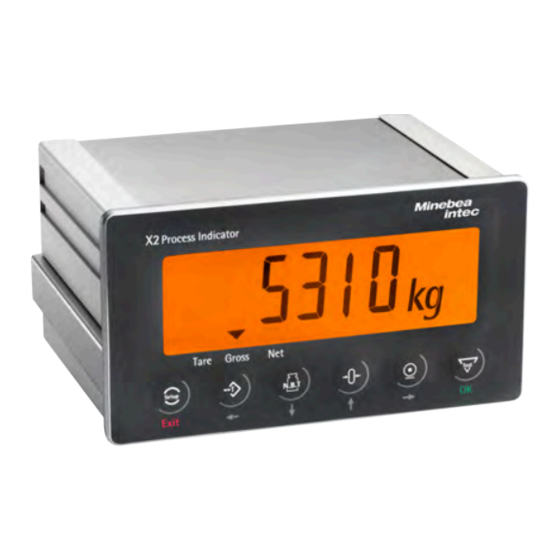
3. Device description | 16 3 Device description General information The indicator is equipped with a six-digit 7-segment display and additional status indication. Local operation is performed using 6 double-function keys. Overview of the device – Accuracy 6,000 d (acc. to OIML R76 Class III) for the weighing electronics –... -
Page 17: Communication Protocols
3. Device description | 3.3 - Housing | 17 3.2.1 Communication protocols For RS‑232-/RS‑485 interfaces: – Remote display protocol – Printer – SMA protocol – ModBus RTU protocol Field bus slave (options): ProfiBus‑DP – – DeviceNet – ProfiNet I/O – EtherNet/IP Housing 3.3.1... - Page 18 3. Device description | 3.3 - Housing | 18 Dimensions Rear view Side view all dimensions in mm all dimensions in mm Front view Control panel cut-out The control panel cut-out must be made be fore installing the device. all dimensions in mm all dimensions in mm...
- Page 19 3. Device description | 3.3 - Housing | 19 3.3.2 Table-top housing The keypad and the display form a unit with the front of the upper part of the housing. All cable connections are located inside the device. The cables are to be con nected via the cable glands located on the rear of the device.
- Page 20 3. Device description | 3.3 - Housing | 20 Front view Isometric view all dimensions in mm Side view Rear view all dimensions in mm all dimensions in mm...
-
Page 21: Indicator Front
3. Device description | 3.3 - Housing | 21 3.3.3 Indicator front Panel device Pos. Name 7-segment display Keypad... - Page 22 3. Device description | 3.3 - Housing | 22 Table-top device Pos. Name 7-segment display Keypad...
-
Page 23: Overview Of Connections
3. Device description | 3.3 - Housing | 23 3.3.4 Overview of connections 3.3.4.1 Panel device... - Page 24 3. Device description | 3.3 - Housing | 24 Connection Description Analog weighing electronics Analog weighing platforms and analog load cells can be connected (via a cable junction box). 3 digital inputs Contact inputs, for example, can be implemented. See Chapter Digital inputs for an example.
- Page 25 3. Device description | 3.3 - Housing | 25 3.3.4.2 Table-top device In principle, the cables can be fed through all the cable glands that match the cable diameter. The figure below shows a cabling suggestion. Pos. Connection Description Analog weighing electronics Analog weighing platforms and analog load cells can be connected (via a cable junction box).
- Page 26 3. Device description | 3.3 - Housing | 26 Pos. Connection Description Pressure compensation element It provides pressure equalization in the device. 3 digital outputs Current or voltage inputs, for example, can be im plemented. See Chapter Digital outputs for an ex ample.
- Page 27 3. Device description | 3.3 - Housing | 27 3.3.4.3 Plug-in cards Product Description Position PR 5310/20, ../21, ../ Analog output 16 Bits, 0/4-20 mA Slot 1 30, ../31 For more information see Chapter Analog output Analog output. PR 5310/23, ../24, ../ ProfiBus-DP-V0 Slave with 9,6 kbit/s to...
-
Page 28: Device Installation
4. Device installation | 28 4 Device installation General instructions Before starting work, please read Chapter 2 and follow all instructions. WARNING Warning of hazardous area and/or personal injury Installation work must be performed by trained and qualified personnel who are aware of and able to deal with the related hazards and take suitable measures for self-protection. -
Page 29: Mechanical Preparation
4. Device installation | 4.2 - Mechanical preparation | 29 Mechanical preparation 4.2.1 Storage and transport conditions NOTICE Material damage is possible. Unpacked devices may lose their precision due to strong vibrations; strong vibrations may impair the safety of the device. Do not subject the device to extreme temperatures, moisture, shocks, and vibrations. -
Page 30: Checking The Equipment Supplied
4. Device installation | 4.2 - Mechanical preparation | 30 4.2.4 Checking the equipment supplied – Indicator – Options and accessories in accordance with the delivery note – Safety instructions 4.2.5 Acclimatizing the device If a cold device is brought into a warm environment, condensation may form. Keep the device disconnected from the mains and allow it to acclimatize at room temperature for approx. two hours. - Page 31 4. Device installation | 4.2 - Mechanical preparation | 31 Table-top device The screen connection is made in the cable gland, see Chapter Installation of a cable with gland. NOTICE Material damage is possible. If a cable gland is not used, it must be equipped with one of the supplied plugs.
- Page 32 4. Device installation | 4.2 - Mechanical preparation | 32 1. Unscrew the sleeve screw cap (1). 2. Slide the cap (1) and plastic cone (3) onto the cable (2). 3. Guide the cable (5) through the gland (6). 4. Fold the cable screen (4) over the lower part of the terminal insert (3) (approx.
-
Page 33: Emc-Compliant Installation
4. Device installation | 4.2 - Mechanical preparation | 33 4.2.7 EMC-compliant installation 4.2.7.1 Connecting the screens and the equipotential bonding conductor Panel device Screens and potential equalization must be connected in the grounding ter minals (1). Table-top device Screens and potential equalization (1) must be connected in the cable gland (3), ground terminal (2) and in the plug connector (PE). -
Page 34: Hardware Construction
4. Device installation | 4.3 - Hardware construction | 34 Hardware construction 4.3.1 Main board The following components are located on the main board: Pos. Name Slot for analog weighing electronics board Slot for keypad Slot for display board Slot for plug-in cards (slot 1), see Chapter Plug-in cards Standard interface with RS-232, RS-485, digital inputs and outputs Lithium battery... -
Page 35: Analog Weighing Electronics Board
4. Device installation | 4.3 - Hardware construction | 35 4.3.2 Analog weighing electronics board Terminal contact Connection Description + Meas. + Signal/LC output - Meas. - Signal/LC output + Supply + Supply/excitation + Sense + Sense - Sense - Sense - Supply - Supply/excitation The analog weighing electronics board, including CAL switch, is located on... - Page 36 4. Device installation | 4.3 - Hardware construction | 36 Technical data Name Data Pin strip, 28‑pin Internal connection External connection Plug connector, 6-pin Switch cabinet device: screen connection on the grounding terminal Table-top device: screen connection in the cable gland 6‑wire or 4‑wire Number of channels Load cell supply...
-
Page 37: Connection Of Analog Load Cells And Platforms
4. Device installation | 4.3 - Hardware construction | 37 4.3.3 Connection of analog load cells and platforms 4.3.3.1 General instructions The device is equipped with an integrated connection for analog weighing electronics. The interface can be configured by software. Note: The load cell/platform cable is routed in the table-top unit through the cable gland to the plug connector and then connected, see chapter Table-top device... - Page 38 4. Device installation | 4.3 - Hardware construction | 38 Weight indicator terminal Terminal Connection Description Color contact Meas. Signal/LC output green – Meas. – Signal/LC output gray Supply Supply/excitation Sense Sense white – Sense – Sense black – Supply –...
- Page 39 4. Device installation | 4.3 - Hardware construction | 39 4.3.3.2 Connecting an analog weighing platform with a 6-wire cable Connection example Panel device ① Screen ② Potential equalization Connection example table-top device ① Screen ② Cable gland ③ Potential equalization...
- Page 40 4. Device installation | 4.3 - Hardware construction | 40 4.3.3.3 Connecting a load cell with a 4-wire cable Connection example panel device Provide the following links between the terminal contacts: ① from + Supply (+V) to + Sense (+S) ② from – Supply (-V) to – Sense (-S) Further connections: ③ Screen ④ Potential equalization...
- Page 41 4. Device installation | 4.3 - Hardware construction | 41 4.3.3.4 Connecting a load cell with a 6-wire cable Connection example panel device ① Screen ② Potential equalization Connection example table-top device ① Screen ② Cable gland ③ Potential equalization...
- Page 42 4. Device installation | 4.3 - Hardware construction | 42 4.3.3.5 Connecting between 2 and 8 load cells (650 Ω) using a 6-wire connection cable Connections are made via cable junction box PR 6130/.. using connection cable PR 6135/.. or PR 6136/..Recommendation –...
- Page 43 4. Device installation | 4.3 - Hardware construction | 43 Connection example panel device ① Cable junction box ② Screen ③ The cable screen is connected to the load cell housing. ④ Potential equalization...
- Page 44 4. Device installation | 4.3 - Hardware construction | 44 Connection example table-top device ① Cable junction box ② Screen ③ The cable screen is connected to the load cell housing. ④ Potential equalization ⑤ Cable gland...
- Page 45 4. Device installation | 4.3 - Hardware construction | 45 4.3.3.6 Connecting load cells of type series PR 6221 See installation manuals of PR 6221 and PR 6021/08, ../18, ../68S. 4.3.3.7 Testing the measuring circuit A simple test with the load cells connected can be carried out with a multimeter.
- Page 46 4. Device installation | 4.3 - Hardware construction | 46 4.3.3.8 Connecting load cells to an external supply If the total resistance of the load cells is ≤75 Ω (e.g., more than 4 load cells with 350 Ω), an external load cell supply is required. In this case, the internal supply is replaced by a potential-free external supply.
- Page 47 4. Device installation | 4.3 - Hardware construction | 47 Connection example ① + external supply ② 0 external supply ③ - external supply ④ Power supply U = 24 V 0,5 A ⑤ Potential-free ⑥ Potential equalization...
-
Page 48: 1×Rs-232 Interface Und 1×Rs-485 Interface
4. Device installation | 4.3 - Hardware construction | 48 4.3.4 1×RS-232 interface und 1×RS-485 interface The interfaces can be configured via the front-panel keys. RS-232 RS-485 Terminal con Connection Terminal contact Connection tact RS-232 - Tx RS-485 - RxA RS-232 - RTS RS-485 - RxB RS-232 - Rx... - Page 49 4. Device installation | 4.3 - Hardware construction | 49 4.3.4.1 RS-232 interface Technical data Name Data External connection Plug connector, 26-pin Number of channels RS‑232, full duplex Type Transfer rate 1200…38 K4 bit/s Parity None, odd, even Data bits 7/8 bits Input signal level Logic 1 (high) -3 to -15 V...
- Page 50 4. Device installation | 4.3 - Hardware construction | 50 Block diagram 4.3.4.1.1 Connection of a ticket printer via RS-232 The following printers can be connected: YDP05 YDP21...
- Page 51 4. Device installation | 4.3 - Hardware construction | 51 Connection example Panel device ① Screen ② Potential equalization ③ Printer Connection example table-top device ① Screen ② Potential equalization ③ Printer ④ Cable gland...
- Page 52 4. Device installation | 4.3 - Hardware construction | 52 Configuration example PR 5310 Configuration printer The configuration of the printer is not provid - [SI 070] [PrInt] [Port] [r S232] [ProtoC] [rtS.CtS] [b Aud] [9600] [PArIty] [nonE] [bit [StoP] [Coln 1…Coln 12] See also Chapter Configuring the serial in...
- Page 53 4. Device installation | 4.3 - Hardware construction | 53 Connection example table-top device ① D‑Sub 9-pin plug connector (male) ② 5-pin plug connector ③ Potential equalization ④ Cable gland ⑤ Screen Configuration example PR 5310 PR 5110 - [S1 071] [rENdSP] [Port] [r [oP 10] [LInE]...
- Page 54 4. Device installation | 4.3 - Hardware construction | 54 4.3.4.2 RS-485 interface Technical data Name Data External connection Plug connector, 26-pin Number of channels RS‑485, full duplex (4‑wire) Type RS‑485, half duplex (2‑wire) Transfer rate 1200…38 K4 bit/s Signals TxA, RxA, TxB, RxB Potential isolation Cable gauge...
- Page 55 4. Device installation | 4.3 - Hardware construction | 55 4.3.4.2.1 Connection of the remote display PR 5110 via RS-485 The PR 5110 remote display can be connected to the device via the internal RS-485 interface. Connection example panel device ① D‑Sub 9-pin plug connector (male) ② 5-pin plug connector ③ Potential equalization ④ Screen...
- Page 56 4. Device installation | 4.3 - Hardware construction | 56 Switch settings PR 5110 ON: S1, S2, S3 OFF: S4, S5 Configuration example PR 5310 PR 5110 - [SI 071] [rENdSP] [Port] [r [oP 10] [LInE] [rS485] S485] [bAud] [9600] [Mod...
- Page 57 4. Device installation | 4.3 - Hardware construction | 57 Connection example table-top device ① Screen ② Potential equalization ③ Indicator ④ Half duplex ⑤ Cable gland Configuration example - [S1 073] [ModbuS] [Port] [rS485] [bAud] [9600] [PArIty] [non [SLAV] [065] [ModE] [ HALF] Siehe auch Kapitel Configuring the serial interface for ModBus-RTU.
-
Page 58: Digital Inputs And Outputs (3 In/3 Out)
4. Device installation | 4.3 - Hardware construction | 58 4.3.5 Digital inputs and outputs (3 IN/3 OUT) The interfaces can be configured via the front-panel keys. Digital inputs Digital outputs Terminal contact Connection Terminal contact Connection CH 1 + CH 1C CH 1 - CH 2C... - Page 59 4. Device installation | 4.3 - Hardware construction | 59 Technical data Name Data Inputs Number of inputs 3 (CH 1, CH 2, CH 3) Input supply voltage Logic 0: U = 0…5 V or open Logic 1: U = 10…28 V Passive, external power supply required Input current <7 mA @ 24 V <3 mA @ 12 V...
- Page 60 4. Device installation | 4.3 - Hardware construction | 60 4.3.5.1 Digital inputs 3 passive opto-decoupled inputs are permanently built into the device for process control. Block diagram...
- Page 61 4. Device installation | 4.3 - Hardware construction | 61 Contact input Panel device Table-top device ① Screen ② Power supply U = 24 V 0.5 A...
- Page 62 4. Device installation | 4.3 - Hardware construction | 62 4.3.5.2 Digital outputs 3 relay outputs with potential-free change-over contacts for process control. Blockschaltbild...
- Page 63 4. Device installation | 4.3 - Hardware construction | 63 Connection example for relay control (current output) Panel device Table-top device ① Inductive load for free-wheel diode ② Screen ③ Power supply unit U = 24 V 0.5 A The relay switches when the output is active (true). To protect the output circuit, relays must be equipped with free-wheel diodes.
- Page 64 4. Device installation | 4.3 - Hardware construction | 64 Connection example for voltage output Panel device Table-top device ① 2,2 kΩ /1 kΩwith 24 V/12 V ② Screen ③ Power supply unit U = 24 V 0.5 A When the output is active (true), the output voltage drops from 24 V/12 V to 0 V.
-
Page 65: Analog Output
4. Device installation | 4.3 - Hardware construction | 65 4.3.6 Analog output An active analog output is integrated into the device. The interface can be configured by front keys. Terminal contact Connection Screen GNDI +0/4 to 20 mA... - Page 66 4. Device installation | 4.3 - Hardware construction | 66 Technical data Description Data External connection 3-pin plug connector (male) Number 1 active current output: 20 mA, 10 V output voltage via external 500 Ω resis Function Gross/Net weight/Transparent/Selected, config urable Range 0/4-20 mA, configurable Resolution Internal 16 bits binary = 20,000 counts, @ 20 mA Linearity error...
-
Page 67: Analog Output & Profibus-Dp Interface
4. Device installation | 4.3 - Hardware construction | 67 4.3.7 Analog output & Profibus-DP interface An active analog output and a Profibus-DP interface are integrated into the device. The interface can be conigured by front keys. Terminal contact Connection Screen GNDI +0/4-20 mA... -
Page 68: Profibus-Dp Interface
4. Device installation | 4.3 - Hardware construction | 68 4.3.8 ProfiBus-DP interface With the Profibus-DP a centrally directed data exchange between master and slaves is possible. The master (e.g. automation system PLC) carries out the cyclic exchange of process data with the slaves (drives, I/O) one after the other, in a fixed sequence. - Page 69 4. Device installation | 4.3 - Hardware construction | 69 Technical data Description Data D‑Sub 9-pin plug connector (female) External connection Transfer rate 9.6 kbit/s to 12 Mbit/s, baud rate auto-detection Connection mode ProfiBus network, connections can be made/re leased without affecting other stations. PROFIBUS-DP-V0 SLAVE to IEC 61158 Protocol –...
- Page 70 4. Device installation | 4.3 - Hardware construction | 70 ProfiBus connection The device is the only/last slave in the bus. The device is not the only/last slave in the bus. * screen on connector housing * screen on connector housing Allocation of the D-sub 9-pin plug connector Pin assignment Signal...
- Page 71 4. Device installation | 4.3 - Hardware construction | 71 4.3.8.1 ProfiBus adapter board for table-top devices Signal Color code Description Negative RxD/TxD-N to Green A-line RS-485 specification Send/receive data Positive RxD/TxD-P to RS-485 B-line specification Send/receive data The terminating resistor must be turned ON in the last slave.
- Page 72 4. Device installation | 4.3 - Hardware construction | 72 4.3.8.2 Connection diagram for a master with three slaves ① Master (PLC) ④ Terminating resistor ② Slave ON = switched on ③ last slave OFF = switched off...
-
Page 73: Devicenet Interface
4. Device installation | 4.3 - Hardware construction | 73 4.3.9 DeviceNet interface The DeviceNet fieldbus is a complete DeviceNet adapter (slave) with CAN controller. The interface can be configured by front keys. Technical data Description Data Pin strip, 50‑pin Internal connection External connection 5-pin plug connector (female) - Page 74 4. Device installation | 4.3 - Hardware construction | 74 Description Data Cable length Depends on cable type and transmission rate: 100 to 500 m Certificates – Compatible with DeviceNet specification Vol. 1: 2.0, Vol 2: 2.0 ODVA Certificate according to conformity test –...
- Page 75 4. Device installation | 4.3 - Hardware construction | 75 4.3.9.1 LEDs Identif. Description Network status LED Module status LED Network status (NS) LED status Description Comments Module is offline. No power Constant green Module is online. There are one or more con nections.
- Page 76 4. Device installation | 4.3 - Hardware construction | 76 Module status (MS) LED status Description Comments Module is not initialized. – No power – Module has the status "SETUP" or "NW_INIT". Constant green Module is initialized. Normal operation 1 Hz flashing green Missing or incomplete configu...
- Page 77 4. Device installation | 4.3 - Hardware construction | 77 4.3.9.2 Connection diagram for a master with three slaves ① Master (Transciever) ③ last slave ② Slave PR 5310/.. is energized with 33 mA from the DeviceNet bus supply.
-
Page 78: Ethernet/Ip Interface
4. Device installation | 4.3 - Hardware construction | 78 4.3.10 EtherNet/IP interface The EtherNet/IP fieldbus is a complete EtherNet/IP adapter (slave) for network connection. The interface can be configured by front keys. Technical data Description Data Pin strip, 50‑pin Internal connection Transfer rate 100 Mbit/s, full duplex... - Page 79 4. Device installation | 4.3 - Hardware construction | 79 4.3.10.1 LEDs Identif. Description Network status LED Module status LED Green: flashes when there is data traffic (ac tivity) Yellow: lights up when there is an existing con nection (link) Network status (NS) LED status Description...
- Page 80 4. Device installation | 4.3 - Hardware construction | 80 Module status (MS) LED status Description Comments Module is uninitialized – No power – Module has the status "SETUP" or "NW_INIT". Constant green Module is initialized Normal operation 1 Hz flashing green Error after test Error occurred after test.
-
Page 81: Profinet I/O Interface
4. Device installation | 4.3 - Hardware construction | 81 4.3.11 ProfiNet I/O interface The ProfiNet I/O fieldbus is a complete ProfiNet I/O adapter (slave) with CAN controller. The interface can be configured by front keys. Technical data Description Data Pin strip, 50‑pin Internal connection 2×... - Page 82 4. Device installation | 4.3 - Hardware construction | 82 Note: The XML file is available to download online: http://www.minebea-intec.com NOTICE Fieldbus parameters Recommendation for a Siemens S7, for example Fieldbus slave setting: Use DHCP [on] as per the default settings and activate the master as a DHCP server (W [Allocate IP adr via IO controller]).
- Page 83 4. Device installation | 4.3 - Hardware construction | 83 4.3.11.1 LEDs Identif. Description Network status LED Module status LED Green: flashes when there is data traffic (ac tivity) Yellow: lights up when there is an existing con nection (link) Network status (NS) LED status Description...
- Page 84 4. Device installation | 4.3 - Hardware construction | 84 Module status (MS) LED status Description Comments Module is not initialized. – No power – Module has the status "SETUP" or "NW_INIT". Constant green Module is initialized. Normal operation 1 Hz flashing green Error after test Error occurred after test.
-
Page 85: Getting Started
Switching on the device The device is started up via the key pad of the indicator. When the supply voltage is applied to the device, the following information is displayed: Device type PR 5310 Pr5310 Firmware release 01.00.00. Weight display 1350.50 kg... -
Page 86: Overwrite Protection
5. Getting started | 5.6 - Overwrite protection | 86 Overwrite protection 5.6.1 CAL switch Overwrite protection can be activated via a CAL switch to protect the metrological parameters against unauthorized access. Panel device The CAL switch (1) is located on the rear of the device. Table-top device CAL switch is located on the mainboard and is accessible on the rear of the device, see... -
Page 87: Performing A Factory Reset On The Device
5. Getting started | 5.7 - Performing a factory reset on the device | 87 Performing a factory reset on the device Note: A factory reset can only be performed if the CAL switch is open. Restarting has the following effects on the device –... -
Page 88: Operating
6. Operating | 88 6 Operating Operating and display elements 6.1.1 Indicator display 6‑digit weight values (digit height 18 mm) with the decimal points can be shown on the display. Pos. Description positive value negative value The gross weight value is within ±¼ d of zero Weight value Mass unit, possible are: t, kg, g, lb ▼... -
Page 89: Keypad
6. Operating | 6.1 - Operating and display elements | 89 6.1.2 Keypad Indicator keys Function Set tare The current gross weight is stored in the tare memory, provided that – the weight value is stable. – the device is not in error status. The function depends on the configuration. -
Page 90: Selecting Parameters
6. Operating | 6.1 - Operating and display elements | 90 Menu/navigation keys Function Setup Menu Access the setup menu. Exit Exit Exit the current menu. Confirm Confirm input/selection. Cursor left – Cursor to the left – Selection Cursor down Scroll down in the menu. -
Page 91: Configuration And Adjustment Via The Keypad
6. Operating | 6.2 - Configuration and adjustment via the keypad | 91 5. Press to make your selection. 6. Press to select the digit positions. 7. Press to increase/decrease the number. 8. Press "OK to confirm the input. 9. Press "Exit" to exit a menu. SAVE If a parameter has been changed, appears on the display. - Page 92 6. Operating | 6.2 - Configuration and adjustment via the keypad | 92 C P · Metrology parameters – 0 10 MEAtIM Measurement time – 0 11 FILtEr Digital filter – 0 12 FCut Filter frequency – 0 13 tStMod Test mode –...
- Page 93 6. Operating | 6.2 - Configuration and adjustment via the keypad | 93 1oF.Cnd Condition – 0 32 LIM.2on Limit 2 "on" 2on.VAL Value 2on.ACt Action 2on.Cnd Condition – 0 33 LIM.2oF Limit 2 "off" 2oF.VAL Value 2oF.ACt Action 2oF.Cnd Condition –...
- Page 94 6. Operating | 6.2 - Configuration and adjustment via the keypad | 94 – 0 46 InP.2oF Input 2 "off" 2oF.ACt Action 2oF.Cnd Condition – 0 47 InP.3on Input 3 "on" 3on.ACt Action 3on.Cnd Condition – 0 48 InP.3oF Input 3 "off" 3oF.ACt Action 3oF.Cnd...
- Page 95 6. Operating | 6.2 - Configuration and adjustment via the keypad | 95 – 0 56 Wgt-20 Weight at 20 mA – 0 57 CAL-04 Weight at 4 mA. Adjustment of the analog output, see Chapter Adapting the analog output. –...
- Page 96 6. Operating | 6.2 - Configuration and adjustment via the keypad | 96 S I · Serial ports parameter – 0 70 PrInt Printer: Configuring the interface, see Chapter Configuring the serial interface for the printer – 0 71 rEMdSP Remote display: Configuring the interface, see Chapter Configuring the serial interface for the remote display...
- Page 97 I F · Information – 0 90 SoFt.VE Software version – 0 91 SLot EMPty Empty or PR 5310 card type – 0 92 rS-232 Protocol assigned to the RS232 interface – 0 93 rS-485 Protocol assigned to the RS485 interface –...
-
Page 98: Date & Time
6. Operating | 6.2 - Configuration and adjustment via the keypad | 98 6.2.2 Date & time 1. Press and hold for 2–3 seconds. SEtuP appears on the display. 2. Press "OK". Cd 000 appears on the display ( flashes). dt 068 3. -
Page 99: New Adjustment Of The Internal Weighing Point
6. Operating | 6.2 - Configuration and adjustment via the keypad | 99 6.2.3 New adjustment of the internal weighing point Example: Max (max. capacity) 600 kg Scale interval 0.2 kg Set dead load with empty scale. Note: When a new adjustment is started, the device has the following default settings: Max 3000 kg Scale interval 1 kg... - Page 100 6. Operating | 6.2 - Configuration and adjustment via the keypad | 100 ------.kg appears on the display. -----.-kg 10. Press to move the decimal point one place to the left 11. Press "OK". 00300.0kg appears on the display ( flashes).
- Page 101 6. Operating | 6.2 - Configuration and adjustment via the keypad | 101 A weight value for the dead load appears on the display. 25. Press "OK". 00000.0kg The dead load is set. appears on the display. Defining the Span (Cd 004) 26.
- Page 102 6. Operating | 6.2 - Configuration and adjustment via the keypad | 102 Cd 005 appears on the display. 37. Press "OK". uVolt.d appears on the display. 38. Press "OK". The measuring signal in µV/d appears on the display. 39. Press "OK". Cd 006 appears on the display.
-
Page 103: Changing The Dead Load Of The Internal Wp
6. Operating | 6.2 - Configuration and adjustment via the keypad | 103 6.2.4 Changing the dead load of the internal WP If the dead load (weight of empty scale/empty container) has changed due to modifications to the mechanics, proceed as described below. WP = weighing point Start 1. - Page 104 6. Operating | 6.2 - Configuration and adjustment via the keypad | 104 Saving and exiting 14. Press "Exit". SAVE appears on the display. 15. Press "OK". appears on the display. 16. Press "OK". SAVE ... appears on the display while saving is in progress. 17.
- Page 105 6. Operating | 6.2 - Configuration and adjustment via the keypad | 105 Calculate dead load Voltage equivalent [mV/V] = dead load × load cell sensitivity C [mV/V]/ load cell capacity (maximum capacity E × number of load cells) Load cell sensitivity C = rated output C (see technical data for the load cell) Normally, calculation of the dead load (scale without load or empty vessel) is...
-
Page 106: Displaying Adjustment Data Of The Internal Wp
6. Operating | 6.2 - Configuration and adjustment via the keypad | 106 6.2.5 Displaying adjustment data of the internal WP WP = weighing point Procedure 1. Press and hold for 2–3 seconds. SEtuP appears on the display. 2. Press "OK". Cd 000 appears on the display ( flashes). - Page 107 6. Operating | 6.2 - Configuration and adjustment via the keypad | 107 dEAdLo appears on the display. 14. Press "OK". The mV/V value for the dead load appears on the display. 15. Press "OK". Cd 004 appears on the display. 16.
-
Page 108: Displaying Adjustment Data For Dead Load And Max
6. Operating | 6.2 - Configuration and adjustment via the keypad | 108 6.2.6 Displaying adjustment data for dead load and Max Normally, all device settings are documented/printed out upon commissioning. If a faulty device is replaced by a new one and no new adjustment is performed, the values for the dead load and the max. -
Page 109: Entering Metrology Parameters
6. Operating | 6.2 - Configuration and adjustment via the keypad | 109 13. Press "OK". The mV/V value for the max. capacity (Max) appears on the display. 14. Note the displayed value. 15. Press "Exit" to exit the setup menu. 6.2.7 Entering metrology parameters 1. - Page 110 6. Operating | 6.2 - Configuration and adjustment via the keypad | 110 The following includes examples of interference signals for the different filter types: Bessel filter Aperiodic filter Butterworth filter Tschebyscheff filter A digital filter can be switched on only with the measure time set to ≤160 ms.
- Page 111 6. Operating | 6.2 - Configuration and adjustment via the keypad | 111 [Cut-off frequency] CP 012 FCut The smaller the cutoff frequency, the slower the measurement and the more stable the measurement result. Input: 0.1…80.00 Hz The available options depend on the measure time. FCut The parameter can only be selected if the digital filter is switched on.
- Page 112 6. Operating | 6.2 - Configuration and adjustment via the keypad | 112 [Zerotrack step] CP 020 ZEtStP If a weight change exceeds the adjusted value, automatic tracking does not function any more. Setting range for automatic tracking increments: 0.25…10.00 d CP 021 ZEttIM [Zerotrack time] Time interval for automatic zerotrack.
-
Page 113: Limits
6. Operating | 6.2 - Configuration and adjustment via the keypad | 113 6.2.8 Limits 6.2.8.1 Functions of the limits Each limit consists of a switch-on and a switch-off point for definition of a hys teresis. The 3 pairs of values must be entered according to the same princi ple. - Page 114 6. Operating | 6.2 - Configuration and adjustment via the keypad | 114 Example 2: If limits 1 and 2 are the same for 'On' and 'Off' (on = off), – output 1 (Limit 1 out) switches ON if the weight (Wgt) exceeds the value. –...
- Page 115 6. Operating | 6.2 - Configuration and adjustment via the keypad | 115 6.2.8.2 Configuring limits 1. Press and hold for 2–3 seconds. SEtuP appears on the display. 2. Press "OK". Cd 000 appears on the display ( flashes). 3. Press 4.
- Page 116 6. Operating | 6.2 - Configuration and adjustment via the keypad | 116 [Limit 3 off] LI 035 LIM.3oF 3oF.VAL Input: Weight value under 3oF.ACt Selection: Action under , see Chapter Defining actions 3oF.Cnd Selection: Condition under , see Chapter Setting conditions 5.
-
Page 117: Configuring Digital Inputs
6. Operating | 6.2 - Configuration and adjustment via the keypad | 117 6.2.9 Configuring digital inputs For each of the 3 inputs, an action can be defined for the signal change from 0 to 1 (on) and from 1 to 0 (off), see Chapter Defining actions. - Page 118 6. Operating | 6.2 - Configuration and adjustment via the keypad | 118 nonE appears on the display. b16=1 10. Press to select the condition (in this case, condition limit 1 off = active), see Chapter Setting conditions. 11. Press "OK". dI 044 appears on the display.
- Page 119 6. Operating | 6.2 - Configuration and adjustment via the keypad | 119 6.2.9.1 Defining actions Actions can be selected (bits set) for all digital inputs (see table). SPM addresses for the digital inputs, see Chapter System data. Selection list for the actions Action SPM bit Description...
-
Page 120: Setting Conditions
6. Operating | 6.2 - Configuration and adjustment via the keypad | 120 6.2.10 Setting conditions 1on.Cnd 3on.Cnd The markers can also be linked to a condition under … 1oF.Cnd 3oF.Cnd … Selection list for the conditions Condition SPM bit Description none No condition... - Page 121 6. Operating | 6.2 - Configuration and adjustment via the keypad | 121 Condition SPM bit Description b65 = 0 X65 = 0 Marker bit 2 not set, markers are reset af ter power on. b66 = 0 X66 = 0 Marker bit 3 not set, markers are reset af...
-
Page 122: Configuring Digital Outputs
6. Operating | 6.2 - Configuration and adjustment via the keypad | 122 Condition SPM bit Description b66 = 1 X66 = 1 Marker bit 3 set, markers are reset after power on. 6.2.11 Configuring digital outputs The desired function for output 1 to output 3 is configured by selecting a signal from the list. - Page 123 6. Operating | 6.2 - Configuration and adjustment via the keypad | 123 Function SPM bit Description b57 = 0 X57 = 0 For internal use only. b58 = 0 X58 = 0 Indicator not tared. b64 = 0 X64 = 0 Marker bit 1 not set, markers are reset af...
- Page 124 6. Operating | 6.2 - Configuration and adjustment via the keypad | 124 Function SPM bit Description b64 = 1 X64 = 1 Marker bit 1 set, markers are reset after power on. b65 = 1 X65 = 1 Marker bit 2 set, markers are reset after power on.
- Page 125 6. Operating | 6.2 - Configuration and adjustment via the keypad | 125 1. Press and hold for 2–3 seconds. SEtuP appears on the display. 2. Press "OK". Cd 000 appears on the display ( flashes). do 040 3. Press (3×) to select 4.
-
Page 126: Configuring The Analog Output
6. Operating | 6.2 - Configuration and adjustment via the keypad | 126 6.2.12 Configuring the analog output Parameter table Parameter Selection Description [Mode] [Off] Analog output is unused. [Transparent] Value output in D30. Instrument is controlled via PLC. [Gross] Gross weight output in D8. - Page 127 6. Operating | 6.2 - Configuration and adjustment via the keypad | 127 Parameter Selection Description [On > Max] [linear] In the event of a weight >Max, the analog out put is retained. This is only possible if the out put value for Max is <20 mA.
- Page 128 6. Operating | 6.2 - Configuration and adjustment via the keypad | 128 GroSS appears on the display. 6. Press to select the corresponding mode, see parameter table. 7. Press "OK". Ao 051 appears on the display. 8. Press "OK". AnA.rnG appears on the display.
- Page 129 6. Operating | 6.2 - Configuration and adjustment via the keypad | 129 21. Press "OK". 20 MA appears on the display. 22. Press to select the corresponding output value, see parameter table. 23. Press "OK". Ao 055 appears on the display. 24.
- Page 130 6. Operating | 6.2 - Configuration and adjustment via the keypad | 130 6.2.12.1 Adapting the analog output The output current can be adjusted in small ranges. This is required if small deviations from the nominal value occur in a connected PLC. 1.
-
Page 131: Entering Operating Parameters
6. Operating | 6.2 - Configuration and adjustment via the keypad | 131 6.2.13 Entering operating parameters 1. Press and hold for 2–3 seconds. SEtuP appears on the display. 2. Press "OK". Cd 000 appears on the display ( flashes). 3. -
Page 132: Configuring Serial Interfaces
6. Operating | 6.2 - Configuration and adjustment via the keypad | 132 oP 067 tiMout [Timeout] Automatically exits the setup menu (in weighing mode) after a defined duration. Input: 00…59 4. Press "Exit" to exit the setup menu. 5. Save the changes. 6.2.14 Configuring serial interfaces 6.2.14.1... - Page 133 6. Operating | 6.2 - Configuration and adjustment via the keypad | 133 [Stop bits] StoP Units for transmission protocols Selection: 1, 2 Coln 1 Coln 12 Only with RS-232: [Line 1…12] … ModE Only with RS-485: [Mode] HALF FuLL Selection: [Half duplex] , full duplex with the lines Coln 1...
- Page 134 6. Operating | 6.2 - Configuration and adjustment via the keypad | 134 6.2.14.2 Configuring the serial interface for the remote display 1. Press and hold for 2–3 seconds. SEtuP appears on the display. 2. Press "OK". Cd 000 appears on the display ( flashes).
- Page 135 6. Operating | 6.2 - Configuration and adjustment via the keypad | 135 Port [Interface] nonE rS232 rS485 Selection: none , RS-232 , RS-485 bAud [Baud rate] Baud rate of the data transfer Selection: 1200, 2400, 4800, 9600 (default), 19200, 38400 ModE Only with RS-485: [Mode] HALF...
-
Page 136: Entering Fieldbus Parameters Using Front-Panel Keys
6. Operating | 6.2 - Configuration and adjustment via the keypad | 136 [Stop bits] StoP Units for transmission protocols Selection: 1, 2 ModE Only with RS-485: [Mode] HALF FuLL Selection: [Half duplex] , full duplex 6. Press "Exit" to exit the setup menu. 7. -
Page 137: Displaying System Information
3. Select the individual parameters and modify if required, see Chapters Parameter table (setup) Selecting parameters. IF 090 Soft.Ve [Software version] Display: Software Version IF 091 Slot [Interface] EMPtY Display: or PR 5310 card type IF 092 Rs-232 [RS-232 interface] Display: none, printer, remote display, SMA, ModBus-RTU... -
Page 138: Printing Configuration Data
6. Operating | 6.3 - Other functions via keypad | 138 [RS-485 interface] IF 093 Rs-485 Display: none, printer, remote display, SMA, ModBus-RTU IF 094 Rtc.bat [Battery status] bAt oK bAt nOt oK Display: OK , not OK 4. Press "Exit" to exit the setup menu. 6.2.17 Printing configuration data Note:... -
Page 139: Testing Digital Inputs
6. Operating | 6.3 - Other functions via keypad | 139 4. Press "OK". kEy-0 appears on the display. 5. Press the keys. The corresponding key ID appears on the display, see below. kEy-1 kEy-2 kEy-3 kEy-4 kEy-5 kEy-6 If the correct key ID is not shown for a key, the keypad is defective. 6. -
Page 140: Testing Digital Outputs
6. Operating | 6.3 - Other functions via keypad | 140 6. Switch on the inputs externally. The following appears on the display: Digital input Identifier 1 0 0 Input 1 on 0 1 0 Input 2 on 0 0 1 Input 3 on 1 1 1 Input 1–3 on... -
Page 141: Testing The Rs-232 Interface
6. Operating | 6.3 - Other functions via keypad | 141 6. Switch on the inputs externally. The following appears on the display: Digital input Identifier 1 0 0 Input 1 on 0 1 0 Input 2 on 0 0 1 Input 3 on 1 1 1 Input 1–3 on... -
Page 142: Testing The Rs-485 Interface
6. Operating | 6.3 - Other functions via keypad | 142 6.3.5 Testing the RS-485 interface 1. Press and hold for 2–3 seconds. SEtuP appears on the display. 2. Press tESt appears on the display. 3. Press "OK". appears on the display. 4. - Page 143 6. Operating | 6.3 - Other functions via keypad | 143 7. Press "OK". Pressing the key increases the counting in line with the parameter settings. Every time the "OK" key is pressed, 1,000 mA are added to the output (up to a maximum of 20,000 mA). 8.
-
Page 144: Modbus Protocol
7. ModBus protocol | 144 7 ModBus protocol General description The ModBus protocol implemented in the device enables rapid, simple, and reliable communication between a PC or PLC and up to a maximum of 99 de vices. The ModBus protocol allows access to all data published in the SPM table of the relevant application. -
Page 145: Sma Protocol
8. SMA protocol | 145 8 SMA protocol General description The protocol of the "Scale Manufacturers Association" (SMA) provides a sim ple access to the scale. It can be used for reading data, or for executing func tions. The RS-485 interface is used as an interface. Fixed interface settings are 8 bits, no parity and 1 stop bit. -
Page 146: Fieldbus Interface
9. Fieldbus interface | 146 9 Fieldbus interface General notes The PR 5310 can be included under a communication master (e.g. Siemens S7 ProfiBus) as a field bus slave. The update rate is 50 ms. The field bus exchanges its data cyclically with each slave. That means: In each cycle, the entire data range is written and read, even if there are no changes to the data content. -
Page 147: Data Exchange Range
9. Fieldbus interface | 9.2 - Scale protocol | 147 9.2.1 Data exchange range Overview Byte 0, 1, 2, 3 6, 7 MOSI Write data Read_Value_Select Write_Value_Select Control bits MISO Read data Read_Value_Selected Status bits Status bits Write window (MOSI) Byte Field Description... - Page 148 9. Fieldbus interface | 9.2 - Scale protocol | 148 Field Size Function Write data 4 bytes Data to be written as a binary 32-bit value with plus or minus sign. Data type: DINT Read_Value_Select 1 byte Function for selecting the read request Write_Value_Select 1 byte Function for selecting the write request...
- Page 149 9. Fieldbus interface | 9.2 - Scale protocol | 149 Read window (MISO) Byte Field Description Read data (MSB) Contains the data to be written, e.g. gross value. Read data Read data Read data (LSB) Read_Value_Selected Read_Value_Select (func tion) from the write win dow is mirrored if the data in "Read data"...
- Page 150 9. Fieldbus interface | 9.2 - Scale protocol | 150 Field Size Function CmdError 1 bit The device has interrupted the execution of a command (e.g., standstill could not be reached within the defined standstill time). The error number can be read from "LASTER ROR", see Chapter Function number 4: adjust...
-
Page 151: Reading And Writing Data With Function Numbers
9. Fieldbus interface | 9.2 - Scale protocol | 151 9.2.2 Reading and writing data with function numbers 9.2.2.1 Reading data Procedure: 1. Write the function number as Read_Value_Select in byte 4 of the write window (e.g., 9 = net weight). 2. - Page 152 9. Fieldbus interface | 9.2 - Scale protocol | 152 9.2.2.2 Writing data Procedure: 1. Wait until Write_Active = 0 in the read window (slave is ready to receive new data). 2. Write value in bytes 0-3 of the write window. 3.
-
Page 153: Reading And Writing Bits Directly
9. Fieldbus interface | 9.2 - Scale protocol | 153 9.2.2.3 Writing bits In addition to the control bits in bytes 6/7, further bits can be set and, if necessary, reset directly with Write_Value_Select. To set bits 80 to 124, the corresponding function number is written to Write_Value_Select (see Chapter Function numbers). - Page 154 9. Fieldbus interface | 9.2 - Scale protocol | 154 9.2.3.2 Writing control bits Some device functions can be executed by setting bits directly in bytes 6 and 7 (control bytes) of the write window. Action of the master Slave reaction Set bits in the control byte.
-
Page 155: Waiting For The Result Of The Action
9. Fieldbus interface | 9.2 - Scale protocol | 155 9.2.4 Waiting for the result of the action When an action requiring more time is started, the end of execution can also be waited for. Action of the master Slave reaction For setting bits, see Chapter Writ... -
Page 156: Function Numbers
9. Fieldbus interface | 9.2 - Scale protocol | 156 9.2.5 Function numbers Function numbers are written to MOSI by the master (SPS) and reflected in MISO by the PR 5310. – Function number 0: I/O status bits (read), see Chapter Function number 0: I/O status bits (read) –... - Page 157 9. Fieldbus interface | 9.2 - Scale protocol | 157 9.2.5.1 Function number 0: I/O status bits (read) Dynamic status Bit 7 Bit 6 Bit 5 Bit 4 Bit 3 Bit 2 Bit 1 Bit 0 Byte 0 Input 3 Input 2 Input 1 Byte 1...
- Page 158 9. Fieldbus interface | 9.2 - Scale protocol | 158 Field Function InsideZSR The gross weight value is within the zero setting range. Standstill The scale is stable. OutOfRange Below zero or above Max (FSD). The measuring signal is higher than the permissible range of 36 mV.
- Page 159 9. Fieldbus interface | 9.2 - Scale protocol | 159 9.2.5.3 Function number 2: state-controlled action bits (read) Display of signal state Bit 7 Bit 6 Bit 5 Bit 4 Bit 3 Bit 2 Bit 1 Bit 0 Byte 0 Byte 1 Byte 2 87: Get...
- Page 160 9. Fieldbus interface | 9.2 - Scale protocol | 160 Byte Description 1: UNIT One byte for the weight unit; content in decimal form: 0 to 2 = g (grams) 3 = kg (kilograms) 4 = t (tons) 5 = lb (pounds) 2: STEP One byte for the scale interval;...
- Page 161 9. Fieldbus interface | 9.2 - Scale protocol | 161 Byte Description Last error byte; see also CmdError bit, number of LASTER 3: LASTERROR ROR: 30 = weight < dead load 31 = no standstill was achieved (e.g., when taring). 35 = weight exceeds allowed range 40 = CAL switch locked 41 = transmitter not in calibration mode...
- Page 162 TYPE MSB Byte 1 TYPE LSB Byte 2 MAINVERSION Byte 3 SUBVERSION e.g.: PR 5310 Rel 1.23 = 53100123 9.2.5.7 Function number 6: serial number of the weighing point (read) Bit 7 Bit 6 Bit 5 Bit 4 Bit 3...
- Page 163 9. Fieldbus interface | 9.2 - Scale protocol | 163 9.2.5.9 Function number 8–22: weight data (read) The gross, net, and tare weight are stored as a DINT fix point. The real data value is derived from DINT and EXPO as follows: (-EXPO) Value = reading...
- Page 164 9. Fieldbus interface | 9.2 - Scale protocol | 164 9.2.5.11 Function number 30, 31: Fixed values (Read/Write) Function number 30 Fixed value for analog output, value (num) 0 20000 corresponds to 20 mA Fixed value for preset tare, see also SetFixTare, Get Function number 31 FixTare in Chapter Data exchange...
- Page 165 9. Fieldbus interface | 9.2 - Scale protocol | 165 9.2.5.13 Function number 112–124: transition-controlled action bits (write) For setting bits, see Chapter Writing bits As soon as the bit has been set, it is reset internally and the process is carried out;...
-
Page 166: Example: Reading The Gross Weight
9. Fieldbus interface | 9.2 - Scale protocol | 166 9.2.6 Example: reading the gross weight Input range (MOSI) Byte Value Description Read the gross weight (for function number 8, see Chapter Function number 8–22: weight data (read)) - Page 167 9. Fieldbus interface | 9.2 - Scale protocol | 167 Output range (MISO) Byte Value Description Gross weight - byte 0 (MSB) Gross weight - byte 1 Gross weight - byte 2 Gross weight - byte 3 (LSB) Gross weight request de tected.
-
Page 168: Special Note For Devicenet And Ethernet/Ip
9. Fieldbus interface | 9.2 - Scale protocol | 168 9.2.7 Special note for DeviceNet and EtherNet/IP With these fieldbus types, the sequence of the bytes (only applicable for words and individual bytes) is inverted. With long words, this problem does not arise due to compensation by the firmware. -
Page 169: 0 Spm
10. SPM | 169 10 SPM 10.1 General notes The memory accessible to the user is the SPM (Scratch Pad Memory). This memory is used to store lots of internal data from which weights, statuses and reports can be read and control data can be written. The SPM table can be accessed via ModBus communication and fieldbus with SPM interface. -
Page 170: Addressing
10. SPM | 10.3 - Addressing | 170 Data type Description Value range DATE_AND_TIME date and time of day see DATE and TIME_OF_DAY STRING variable-long charac max. 255 characters (ISO) ter string WSTRING variable-long wide max. 255 characters (Uni character string code) BYTE bit-sequence 8... -
Page 171: System Data
10. SPM | 10.4 - System data | 171 10.4 System data SPM address Data type Function X0–X2 BOOL Digital input 1–3 X8–10 BOOL Digital output 1–3 X16–18 BOOL Output limit 1 1–3 BYTE Indicator status BOOL ADC error BOOL >Max (max. - Page 172 10. SPM | 10.4 - System data | 172 SPM address Data type Function BOOL Read/write marker bit 1 BOOL Read/write marker bit 2 BOOL Read/write marker bit 3 BOOL Switch D11 to net weight. X112 BOOL Zero device. X113 BOOL Tare device X114 BOOL Reset the tare of the device...
- Page 173 10. SPM | 10.4 - System data | 173 SPM address Data type Function UDINT Serial number (board number) Counter will be increased for every measured value. DINT Current gross weight DINT Current net weight DINT Current tare weight DINT Current gross/net weight selected with X72 DINT Max.
-
Page 174: 11 Error Messages
11. Error messages | 174 11 Error messages 11.1 Error messages measuring circuit The internal weighing electronics can generate error messages, which are shown on the display. Display Error Possible cause Error 1 Internal arithmetic overflow – Faulty calibration values. Error 2 The measuring signal is higher than –... -
Page 175: General Error Messages
11. Error messages | 11.2 - General error messages | 175 11.2 General error messages Display Error and Possible Cause Err 10 Test is active, no gross weight. Err 11 No weight value (e.g. wrong string input). Err 12 Weighingpoint is not started/in standby. Err 14 Weighingpoint is busy for a time, dont show error message. - Page 176 11. Error messages | 11.2 - General error messages | 176 Display Error and Possible Cause Err 71 A weight error occurs during calibration via the front panel if the connection to the weighing point is interrupted. Err 73 Dead load <-0.1 mV/V Err 74 Arithmetic overflow Err 75...
-
Page 177: Error Numbers @ "Last_Error
11. Error messages | 11.3 - Error numbers @ "LAST_ERROR" | 177 11.3 Error numbers @ "LAST_ERROR" 11.3.1 Weighing point errors Number Display Cause test active Test is active, no weights. cal active Adjustment is active, no weights. no standstill No standstill of the scale. -
Page 178: 2 Maintenance/Repairs/Cleaning
12. Maintenance/repairs/cleaning | 178 12 Maintenance/repairs/cleaning 12.1 Maintenance Maintenance work may only be carried out by authorized technical personnel with expert knowledge of the hazards involved and the required precautions. Maintain and check the device regularly. The periods must be determined by the operator, but should not exceed one year. -
Page 179: Replacing The Battery For Date/Time
12. Maintenance/repairs/cleaning | 12.3 - Solder work | 179 12.2.2 Replacing the battery for date/time If the voltage drops below the specified minimum, or in case of defect, the battery must be replaced by Minebea Intec customer service or by an equivalent trained technician. -
Page 180: 3 Safety Inspection
13. Safety inspection | 180 13 Safety inspection Safe operation of the scale (weighing platform/weighing facility + weighing indicator) is no longer ensured, – if there is visible damage to the connection cable. – if the weighing platform/weighing facility and weighing indicator no longer work. -
Page 181: 4 Disposal
(www.minebea-intec.com). Should you have any further questions, please contact your local service rep resentative or our service center. Minebea Intec GmbH Repair center Meiendorfer Strasse 205 A 22145 Hamburg, Germany Phone: +49.40.67960.333... -
Page 182: 5 Specification
15. Specification | 182 15 Specification 15.1 Equipment supplied Ser. no. Name Process Indicator Safety instructions 9499 059 40001 15.2 General technical data The following characteristics are valid after a warm-up time of at least 60 minutes (reference temperature 23 °C). 15.2.1 Date/time buffer The lithium battery as a buffer for the date/time chip and as a buffer for the supply voltage so the device can be switched on again. -
Page 183: 5.2.3 Supply Voltage Connection Version 24 V Dc
15. Specification | 15.3 - Effect of ambient conditions | 183 15.2.3 Supply voltage connection version 24 V DC Panel indicator Supply voltage = 24 V ±20 % Max. power consumption Primary fuse 1 AT; 250 V; 5×20 mm Table-top indicator Supply voltage = 24 V ±10 % Max. -
Page 184: 5.3.2 Electromagnetic Compatibility (Emc)
15. Specification | 15.3 - Effect of ambient conditions | 184 15.3.2 Electromagnetic Compatibility (EMC) All data in compliance with EN 61326 industrial section Housing High frequency electromagnetic EN 61000-4-3 10 V/m fields (80…2000 MHz) Electrostatic discharge (ESD) EN 61000-4-2 4/8 kV Signal and control Fast transients (burst) EN 61000-4-4 1 kV... -
Page 185: 5.4 Weighing Electronics Data
15. Specification | 15.4 - Weighing electronics data | 185 15.4 Weighing electronics data 15.4.1 Load cells Load cell type Strain gauge 6 or 4-wire connection possible. load cells Supply voltage = 12 V – for I = 160 mA – for max. 8 load cells, each with 650 Ω... -
Page 186: 5.4.3 Accuracy And Stability
15. Specification | 15.4 - Weighing electronics data | 186 15.4.3 Accuracy and stability Accuracy* ≤6,000 d, acc. to OIML R76 Klasse III Min. measuring signal * ≥0.1 mV/V = 1.2 mV corr. to 0.2 µV/d für 6,000 d Linearity* <0,003 % Zero point stability error <0.05 µV/K RTI ≤0.004 %/10 K @ 1 mV/V... -
Page 187: Mechanics
15. Specification | 15.5 - Mechanics | 187 15.5 Mechanics 15.5.1 Housing Panel housing Material Housing Aliminum Steel Rear panel Steel Dimensions See Chapter Housing Weight Net weight 1.15 kg Shipping weight 2.00 kg Table-top housing Material Housing Stainless steel Top section Stainless steel Bottom section... -
Page 188: 6 Appendix
Order information 16.1.1 Ordering numbers Panel devices Model Order no. Description PR 5310/01 9405 1 5310 01 1 Basic, 24 V DC PR 5310/21 9405 1 5310 21 1 Basic, analog output, 24 V DC PR 5310/24 9405 1 5310 24 1 Basic, Profibus-DP &... - Page 189 16. Appendix | 16.1 - Order information | 189 Table-top devices Model Order no. Description PR 5310/11 9405 1 5310 11 1 Basic, 24 V DC PR 5310/31 9405 1 5310 31 1 Basic, analog output, 24 V DC PR 5310/34 9405 1 5310 34 1 Basic, Profibus-DP &...
-
Page 190: 6.1.2 Order Numbers, For India Only
16. Appendix | 16.1 - Order information | 190 16.1.2 Order numbers, for India only Panel devices Model Order no. Description PR 5310/01 9407 1 5310 01 1 Basic, 24 V DC PR 5310/21 9407 1 5310 21 1 Basic, analog output, 24 V DC PR 5310/24 9407 1 5310 24 1 Basic, Profibus-DP &... - Page 191 16. Appendix | 16.1 - Order information | 191 Ex devices Model Order no. Description PR 5310/12 9407 1 5310 12 1 Basic, 24 V DC, table-top de vice, Zone 2/22 PR 5310/32 9407 1 5310 32 1 Basic, analog output, 24 V DC...
-
Page 192: 6.1.3 Order Numbers, For China Only
16. Appendix | 16.1 - Order information | 192 16.1.3 Order numbers, for China only Panel devices Model Order no. Description PR 5310/01 9407 1 5310 01 2 Basic, 24 V DC PR 5310/21 9407 1 5310 21 2 Basic, analog output, 24 V DC PR 5310/24 9407 1 5310 24 2 Basic, Profibus-DP &... -
Page 193: Certificates
16. Appendix | 16.2 - Certificates | 193 Ex devices Model Order no. Description PR 5310/12 9407 1 5310 12 2 Basic, 24 V DC, table-top de vice, Zone 2/22 PR 5310/32 9407 1 5310 32 2 Basic, analog output, 24 V DC... -
Page 194: 6.2.1 Meu23007
16. Appendix | 16.2 - Certificates | 194... - Page 195 16. Appendix | 16.2 - Certificates | 195 български (bg) čeština (cs) dansk (da) Декларация за съответствие Prohlášení o shodě Overensstemmelseserklæring 1. Модел на продукта / Номер на продукта / 1. Model výrobku / číslo výrobku / platné pouze 1. Produktmodel / produktnummer / gælder kun валидно...
- Page 196 16. Appendix | 16.2 - Certificates | 196 Deutsch (de) Eλληνικά (el) español (es) Konformitätserklärung Δήλωση συμμόρφωσης Declaración de conformidad 1. Produktmodell / Produktnummer / gilt 1. Μοντέλο προϊόντος / αριθμός προϊόντος / 1. Modelo de producto/número de producto / ausschließlich für Projekt-Nr.: ισχύει...
- Page 197 16. Appendix | 16.2 - Certificates | 197 eesti keel (et) français (fr) hrvatski (hr) Vastavusdeklaratsioon Déclaration de conformité Izjava o sukladnosti 1. Tootemudel / tootenumber / kehtib vaid 1. Modèle / numéro de produit / valable 1. Model proizvoda / broj proizvoda / vrijedi järgmise projekti puhul: uniquement pour le numéro de projet: samo za broj projekta:...
- Page 198 16. Appendix | 16.2 - Certificates | 198 latviešu valoda (lv) malti (mt) nederlands (nl) Atbilstības deklarācija Dikjarazzjoni ta’ konformità Conformiteitsverklaring 1. Produkta modelis / produkta numurs / derīgs 1. Mudell tal-prodott / numru tal-prodott / validu 1. Productmodel / productnummer / uitsluitend tikai projektam Nr.: biss għan-numru tal-proġett: geldig voor projectnummer:...
-
Page 199: Muk23003
16. Appendix | 16.2 - Certificates | 199... - Page 200 Published by Minebea Intec GmbH Meiendorfer Strasse 205 A | 22145 Hamburg, Germany Phone: +49.40.67960.303 | Email: info@minebea-intec.com www.minebea-intec.com...
Need help?
Do you have a question about the PR 5310 and is the answer not in the manual?
Questions and answers