Table of Contents

Subscribe to Our Youtube Channel
Related Manuals for OPTIKON ASSISTANT


Summary of Contents for OPTIKON ASSISTANT
- Page 1 Cod. 121008S Rev. D ASSISTANT COMBINED EYE-SURGERY SYSTEM SERVICE MANUAL OPTIKON 2000 S.p.A. Via del Casale di Settebagni, 13 - 00138 Rome Italy Phone +39 06 8888355 - Fax. +39 06 8888440 e-mail mailto:sales@optikon.com - www.optikon.com...
- Page 2 Date of print 2009-07-24 OPTIKON ASSISTANT Product Optikon 2000 S.p.A. via del Casale di Settebagni 13 Manufacturer I -00138 Rome, Italy Optikon 2000 SpA is an ISO 9001 and ISO 13485 certified company which manufactures surgical diagnostic devices ophthalmology. Its products are manufactured to satisfy the requirements of...
-
Page 3: Table Of Contents
SENSORS AND AIR BOARD 391120 ........... 6-23 6.3.3 VACUUM SIGNAL FILTER 369130 ............6-28 6.3.4 THE ASSISTANT POWER BOARD 393130 ......... 6-30 CHECKS AND CALIBRATIONS ............7-1 7.1 POWER SUPPLY BOARD 393130 ........... 7-1 7.2 CONTROL BOARD 393200 ............... 7-1 7.3 U/S DRIVER 347888 ................. - Page 4 THIS PAGE IS INTENTIONALLY BLANK...
-
Page 5: Disclaimer
Assistant Service Manual OPTIKON 2000 1. DISCLAIMER OPTIKON 2000 S.p.A. requires the user of this system to carefully read specific warnings found in this manual. Optikon 2000 S.p.A. declares to be liable for safety, reliability and performance only if: • upgrades, calibrations, repairs are carried out by OPTIKON 2000 S.P.A. - Page 6 Assistant Service Manual OPTIKON 2000 THIS PAGE IS INTENTIONALLY BLANK Code 121008S Rev. D...
-
Page 7: Technical Specifications
Assistant Service Manual OPTIKON 2000 2. TECHNICAL SPECIFICATIONS PARAMETER SPECIFICATION Manufacturer:....... OPTIKON 2000 S.p.a. via del Casale di Settebagni, 13 00138 Rome - Italy Model: ........ ASSISTANT Regulatory compliance: ..93/42/EEC Medical Devices Directive (MDD) Technical standards: ....EN 60601-1 ; EN 60601-1-1 ; EN 60601-1-2 ; EN... - Page 8 Assistant Service Manual OPTIKON 2000 PARAMETER SPECIFICATION Flow: ......... at least 30 normal litre/minute @ 500mmHg Default vacuum level: ..... user programmable Available vacuum range: ..5 to 500 mmHg Default flow rate: ....user programmable Available flow rate range: ..
- Page 9 Diathermy cable: ....poles, gauges, ohm, steam autoclavable. Use only original OPTIKON 2000 S.P.A. diathermy cable Control: ......system footswitch ILLUM (ILLUMINATION) Source type: ......dual independent HID lamps Power: ......
- Page 10 Assistant Service Manual OPTIKON 2000 Power: ....... panel or linear control of the U/S power via system footswitch depression. U/S Mode: ......Linear or Panel; Continuous, Short Pulse, Single Burst, Multi-Burst, Continuous Burst, Programmable Emission Mode U/S Timer: ......from 0.00 minutes to 9.59 minutes – Equivalent...
-
Page 11: Diathermy Power Characteristics
Assistant Service Manual OPTIKON 2000 2.1 DIATHERMY POWER CHARACTERISTICS ANTARES ASSISTANT DIATHERMY POWER vs LOAD 100 150 200 250 300 350 400 450 500 550 600 650 700 750 Preset=100% Preset=50% Diathermy Power vs load ASSISTANT ANTARES DIATHERMY POWER vs PRESET... - Page 12 Assistant Service Manual OPTIKON 2000 THIS PAGE IS INTENTIONALLY BLANK Code 121008S Rev. D...
-
Page 13: Warnings
WILL BE EXPOSED TO HEATING EQUIPMENT OR RADIATORS, DIRECT SUNLIGHT, OR ANY OTHER SOURCE OF EXTREMELY HIGH TEMPERATURES. 7) DO NOT INSTALL THE ASSISTANT SYSTEM IN SUCH A WAY THAT THE VENTILATING OPENINGS ARE BLOCKED. 8) BE SURE THAT THE POWER SWITCH ON THE CONTROL CONSOLE IS OFF WHEN PLUGGING IN, OR REMOVING THE POWER CABLE FROM A WALL OUTLET. - Page 14 Assistant Service Manual OPTIKON 2000 11) SEVERE RF BURNS CAN RESULT IF THE DIATHERMY OUTPUT CURRENT IS DIVERTED TO THE OPERATOR BY CARELESS HANDLING. 12) WHEN THE BIPOLAR DIATHERMY HANDPIECE AND A MONITORING SYSTEM ARE USED AT THE SAME TIME, ALL THE ELECTRODES OF THE MONITORING SYSTEM...
- Page 15 TIP. PROLONGED EXPOSURE TO OR DIRECT CONTACT WITH THE VIBRATING TIP MAY CAUSE DAMAGE TO HEALTHY TISSUE. 35) THE PHACO HANDPIECE MUST BE CONNECTED TO THE ASSISTANT IRRIGATION- ASPIRATION SYSTEM AND MUST NOT BE USED WITHOUT IT. 36) AN EXTERNAL STERILIZING FILTER MUST BE INSERTED TO THE AIR SOCKET TO PREVENT INFECTIONS.
- Page 16 LAMP ON. DO NOT POWER ON THE LIGHT IF THE ILLUMINATION MODULE WIRING IS DISCONNECTED.. 47) THE HID LAMPS OF THE ASSISTANT CONTAIN GAS AT A VERY HIGH PRESSURE. THEY MAY EXPLODE CAUSING SERIOUS INJURIES TO THE EYES: WEAR PROTECTIVE GOGGLES DURING BULB REPLACEMENT AND CALIBRATION. HANDLE WITH EXTREME CARE.
-
Page 17: General Information
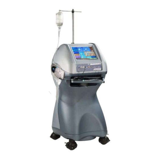
Assistant Service Manual OPTIKON 2000 4. GENERAL INFORMATION 4.1 EQUIPMENT LAYOUT This section contains information on the equipment layout. All operating controls and adjustments are identified and described further on. Sockets and other elements on the front panel are described in Fig. 1. Left side (pump side) of the equipment is described in Figure 2. - Page 18 Assistant Service Manual OPTIKON 2000 1) I/A SYSTEM Disposable I/A tubing set and dual pump cassette. 2) LCD TOUCH-SCREEN DISPLAY By means of this LCD touch-screen the user can - activate the proper functions - setup all parameters - read all actual and preset values...
-
Page 19: Left Side View (Fig.2)
It also prevents sudden vacuum surges, thus stabilizing the anterior chamber. 4) PERISTALTIC PUMP This pump allows peristaltic aspiration in the ASSISTANT. The pump rotor is automatically moved to allow tubing installation and/or Venturi aspiration. 5) I/A CASSETTE RELEASE BUTTON This button allows the I/A cassette to be mounted and removed. -
Page 20: Rear Panel (Figg. 3A & 3B)
2) REMOTE CONTROL This is the remote control connector (for future use). 3) PC UPLINK This is the ASSISTANT-PC interface for data download/upload and software upgrade 4) POWER (ON/OFF MAINS SWITCH ASSEMBLY) The power switch is used to switch on/off the unit. - Page 21 Compressed air supply at a pressure of 500-800 KPa must be (72 to 116 PSI) connected to this input. This air is used by the ASSISTANT to operate Venturi pump and vitrectomy cutter. 3) IV POLE FOOTSWITCH The footswitch controlling the IV pole movement must be connected to this socket.
- Page 22 Assistant Service Manual OPTIKON 2000 LINEAR = Linear control mode (Linear footswitch control). SLOW = Slow vacuum rise time MED = Standard vacuum rise time FAST = Fast vacuum rise time VIT = Vitrectomy Code 121008S Rev. D...
-
Page 23: Internal View
Assistant Service Manual OPTIKON 2000 5. INTERNAL VIEW Fig. 4: Internal view, pneumatics 1 ) SENSORS BOARD ( 391120 ) This board hosts the pressure sensor monitoring input pressure, the electronics and the pressure sensor for the low pressure air tamponade system. - Page 24 Assistant Service Manual OPTIKON 2000 3 ) SILICONE STOP VALVE This valve allows delivering air from the Proportional valve to the Silicone injection connector on the front panel. 4 ) PROPORTIONAL VALVE This electronic valve regulates the pressure of the input compressed air to be delivered to the silicone injection system and to the aspiration Venturi pump under the control of the microprocessor.
- Page 25 Fig. 4a: Internal view, boards location 14) ASSISTANT POWER SUPPLY BOARD (393130) This board generates all the AC and DC voltages needed by the Assistant to operate. 15) ASSISTANT CONTROL BOARD (393200) This board controls all the surgical functions of the Assistant system and it interfaces with the system footswitch and the GUI.
- Page 26 Assistant Service Manual OPTIKON 2000 Fig. 4b-Lamp power supply Code 121008S Rev. D...
- Page 27 Assistant Service Manual OPTIKON 2000 Fig. 4c Internal view, the pump plate, rear 1) CONNECTION TO VENTURI PUMP The silicone tube from the Venturi pump connects to this tube holder. The disposable cassette tank connects at the other side of the tube holder.
- Page 28 Assistant Service Manual OPTIKON 2000 4) STEPPER MOTOR This motor moves the peristaltic pump head to allow I/A cassette installation/removal and activate Venturi pump installation. 5) PERISTALTIC PUMP MOTOR The peristaltic pump DC motor and gearbox is directly connected to the pump rotor.
- Page 29 Assistant Service Manual OPTIKON 2000 FIG.4d Internal view, The GUI hardware Code 121008S Rev. D...
- Page 30 Assistant Service Manual OPTIKON 2000 1) TOUCH SCREEN CONTROLLER BOARD (391160000) This board provides interface between the touch screen and the PS2 input of the PC board. 2) PC BOARD This board is an embedded PC system that includes all the peripherals (RS232, USB, LPT, VGA, PS2, etc.) which are necessary for the GUI.
-
Page 31: Principles Of Operation
6. PRINCIPLES OF OPERATION 6.1 INTRODUCTION The OPTIKON ASSISTANT is a state of the art system designed for both cataract extraction and retinal surgery. The use of a multiple microprocessor architecture combined with some Large Scale Integration circuits (LSI), allows concentrating high technology and top performances in a small and compact unit. - Page 32 Assistant Service Manual OPTIKON 2000 analogical inputs go to the microprocessor (which is capable of up to eight analog inputs and over forty digital I/O lines) and all the digital and analog control outputs are generated by the same microprocessor. Software establishes the links.
- Page 33 Assistant Service Manual OPTIKON 2000 Code 121008S Rev. D...
- Page 34 Assistant Service Manual OPTIKON 2000 Code 121008S Rev. D...
-
Page 35: Control Board 393200
2. Sheet 3/5 contains a series of optocouplers designed to electrically separate the signal circuitry of the microprocessor from the power Darlington transistors that drive the various valves of the ASSISTANT. Sheet 4/5 contains: - The electronic driver of the peristaltic pump. The pump is driven by a 12Vdc motor connected to J12. -
Page 36: Graphic User Interface
- A watch dog circuit to monitor the microprocessor activity. In case of microprocessor failure, this watch dog disables outputs of U6 and U16 TTL latches that control system outputs, putting the ASSISTANT in a safe state. - A serial DAC (MAX5250) that generates the dc voltages to control the pressure preset of the air injection tamponade system and the preset of Ultrasound power. - Page 37 Assistant Service Manual OPTIKON 2000 The relevant connector is J7. The Control Board and the GUI exchanges data using a proprietary eight bit protocol. The correctness of data flow is continuously monitored by both the Control Board software and the GUI software, a rotating logo in the lower part of the user screen ensures that the two software are communicating properly.
- Page 38 Assistant Service Manual OPTIKON 2000 Code 121008S Rev. D...
- Page 39 Assistant Service Manual OPTIKON 2000 Code 121008S Rev. D...
- Page 40 Assistant Service Manual OPTIKON 2000 Code 121008S 6-10 Rev. D...
- Page 41 Assistant Service Manual OPTIKON 2000 Code 121008S 6-11 Rev. D...
- Page 42 Assistant Service Manual OPTIKON 2000 Code 121008S 6-12 Rev. D...
- Page 43 Assistant Service Manual OPTIKON 2000 Code 121008S 6-13 Rev. D...
-
Page 44: U/S Driver 347888
Assistant Service Manual OPTIKON 2000 6.3.1 U/S DRIVER 347888 INTERFACE TO 393200 INTERFACE TO 369140 CONTROL LOGIC ADJUSTABLE DIATHERMY ULTRASOUND POWER SUPPLY The operating philosophy of the U/S Driver 347888 is shown by the block diagram above. The board contains both the U/S driver and the Diathermy driver, they share the same adjustable power supply and they are both controlled by the same microprocessor (NEC’s 78F0078). - Page 45 Assistant Service Manual OPTIKON 2000 controls the VCO, to dynamically correct possible changes, due to changes in the load, of the handpiece resonating frequency. Piezo handpiece is connected to J1 card connector and is driven by a sinusoidal voltage of variable frequency and amplitude. The frequency of the voltage supplied to the handpiece is automatically adjusted by the control circuit in order to match the resonating frequency of the acoustic vibrator.
- Page 46 Assistant Service Manual OPTIKON 2000 U/S Amplifier Section The sinusoidal voltage supplied to the handpiece is picked up at the secondary winding of L1 transformer and filtered through L3 and C9. L1 primary winding is the load of the U/S amplifier, consisting of the two power MOSFET (Q2 and Q3), operated by the U5 driver.
- Page 47 Assistant Service Manual OPTIKON 2000 Amplitude control section and Minimal Stress circuitry Amplitude of sinusoidal signal applied to handpiece is proportional to the direct voltage present at the central tap of primary winding of L1 transformer. It is the output of switching regulator made up by U18,CR2,L2,C4.
- Page 48 Assistant Service Manual OPTIKON 2000 Diathermy driver section (Sheet 2/2) Bipolar diathermy driver generates a voltage of an approximately sinusoidal form, at a fixed frequency of 2 MHz. The maximum output power is 7W on 450 Ohm load. The output of diathermy if floating (insulated from any other voltage or ground), current can flow only between the two opposite poles.
- Page 49 Assistant Service Manual OPTIKON 2000 If a malfunction is detected (i.e. U/S or Diathermy are emitted when not required or a wrong power level), The Control Board stops any power emission driving U/S_SIG and DIA_SIG to a low level. These signal lines are connected to J5.
- Page 50 Assistant Service Manual OPTIKON 2000 Code 121008S 6-20 Rev. D...
- Page 51 Assistant Service Manual OPTIKON 2000 Code 121008S 6-21 Rev. D...
- Page 52 Assistant Service Manual OPTIKON 2000 U/S & Diathermy driver 347888rev.K Code 121008S 6-22 Rev. D...
-
Page 53: Sensors And Air Board 391120
This sheet contains: - The circuitry of the pressure sensor (mounted on the board) used to monitor the ASSISTANT input pressure. The balanced output of the strain gauge sensor is voltage buffered by U1-A-B, then delivered to the differential amplifier U1-C. - Page 54 Assistant Service Manual OPTIKON 2000 Code 121008S 6-24 Rev. D...
- Page 55 Assistant Service Manual OPTIKON 2000 Code 121008S 6-25 Rev. D...
- Page 56 Assistant Service Manual OPTIKON 2000 Code 121008S 6-26 Rev. D...
- Page 57 Assistant Service Manual OPTIKON 2000 NOTE: P3 MOUNTED ON 369130 VACUUM SIGNAL FILTER Code 121008S 6-27 Rev. D...
-
Page 58: Vacuum Signal Filter 369130
(in the ACS3 system of the Dual Pump Disposable Cassette). The board and sensor assembly is located inside the Assistant, on the metal plate that supports the Disposable Cassette and the peristaltic pump. - Page 59 Assistant Service Manual OPTIKON 2000 Code 121008S 6-29 Rev. D...
-
Page 60: The Assistant Power Board 393130
OPTIKON 2000 6.3.4 THE ASSISTANT POWER BOARD 393130 This board generates all the DC voltages needed by the ASSISTANT to operate. The 26Vac-3A secondary of the power transformer (protected by F3 PTC) is rectified by D5 and clipped by Z1 to generate the Power Fail signal. It is also... - Page 61 Assistant Service Manual OPTIKON 2000 Code 121008S 6-31 Rev. D...
- Page 62 Assistant Service Manual OPTIKON 2000 Code 121008S 6-32 Rev. D...
- Page 63 Assistant Service Manual OPTIKON 2000 Code 121008S 6-33 Rev. D...
- Page 64 Assistant Service Manual OPTIKON 2000 Code 121008S 6-34 Rev. D...
- Page 65 Assistant Service Manual OPTIKON 2000 Code 121008S 6-35 Rev. D...
- Page 66 Assistant Service Manual OPTIKON 2000 Code 121008S 6-36 Rev. D...
- Page 67 Assistant Service Manual OPTIKON 2000 Code 121008S 6-37 Rev. D...
- Page 68 Assistant Service Manual OPTIKON 2000 Code 121008S 6-38 Rev. D...
- Page 69 Assistant Service Manual OPTIKON 2000 Code 121008S 6-39 Rev. D...
-
Page 70: Checks And Calibrations
+12 ± 0.5V (Signal) Pin 12 (Signal Ground) Switch the Assistant off and re-connect all the output connectors ( J2 , J4 , J5 ) to the Power Supply Board. 7.2 CONTROL BOARD 393200 Check of reference voltages -Connect multimeter between TP1 and GNDs VAREF 4 ( ±0.1 )Vdc... -
Page 71: U/S Driver 347888
Assistant Service Manual OPTIKON 2000 7.3 U/S DRIVER 347888 Check of reference voltages -Connect multimeter between TP6 and TP3 (GNDs) VREF (2.42÷2.58) Vdc -Connect multimeter between TP7 and TP3 (GNDs) VREF (3.85÷4.15) Vdc -Connect multimeter between TP5 and TP3 (GNDs) Vsupply 10 (9.59÷10.49) Vdc... -
Page 72: The System Calibration Software
• Select Save as • Type in Quit Phaco <enter> The Assistant will exit the normal working software and it will show the Windows CE desktop. • Double tap the Tools icon of “Calibrations” on the desktop. Code 121008S Rev. D... - Page 73 Assistant Service Manual OPTIKON 2000 The System Calibration Software window will appear in the middle of the screen. Fig.5 - The System Calibration Software Code 121008S Rev. D...
- Page 74 Assistant Service Manual OPTIKON 2000 CALIBRATION SOFTWARE INTERFACE DESCRIPTION The Calibration Software User interface is divided in five frames: 1. Mode frame. Allows selection of - Calibration mode - Lookup table construction The Calibration mode allows the various system calibrations described below, The Lookup table construction mode enables the automatic build up of a lookup table for the voltage vs.
- Page 75 Assistant Service Manual OPTIKON 2000 CAUTION: The pressure regulator has a noticeable hysteresis, after each adjustment of the knob position, shortly depress the main paddle of the footswitch beyond position #2 to activate air flow. 4. Remove the pressure gauge from the Main Pressure connector and plug-in the plastic occluder.
- Page 76 Assistant Service Manual OPTIKON 2000 1. Disconnect the Assistant from the external air supply and remove the red plug (fig.4,no.7) to vent residual air from the system. 2. Adjust R47 on the 391120 Sensors board (rotating counter clockwise to decrease) to read 0 mBar on the ASSISTANT display ( External pressure ).
-
Page 77: System Tests And Calibrations
(I/A). To exit the System Calibration Software, restart the system by switching the ASSISTANT off and then back on. 7.6 SYSTEM TESTS AND CALIBRATIONS The tests and calibrations below are performed while in standard mode (standard user software). - Page 78 Assistant Service Manual OPTIKON 2000 80mmHg (step 10mmHg), at each setting verify that the actual reading of the gauge corresponds to the preset value within ± ± ± ± 2 mmHg. Stop the air injection. 2. SILICONE TAMPONADE Connect a pressure gauge with a full scale of at the least 5bar and a resolution equal or better of 0.1bar.
- Page 79 25 to 100. Verify that the diaphragm wheel works correcltly. Repeat the above test for light2. 11. ELECTRIC I.V. POLE Switch the equipment on. Verify that the ASSISTANT tests the pole moving it slightly up and down. Once in the Code 121008S 7-10 Rev. D...
- Page 80 Assistant Service Manual OPTIKON 2000 working program, verify that the pole height can be adjusted with the arrow keys in the Irrigation window and that the actual position of the pole appears in the relevant display. Code 121008S 7-11 Rev. D...
-
Page 81: Illumination Module Test And Calibration
Assistant Service Manual OPTIKON 2000 7.7 ILLUMINATION MODULE TEST AND CALIBRATION Fig. 6a/6b – Illumination module Code 121008S 7-12 Rev. D... -
Page 82: Optical Alignment
Assistant Service Manual OPTIKON 2000 Switch on the lamp by touching the “Light” soft key on the Assistant GUI. The HID lamp s should switch on immediately and it should reach its maximum intensity within 10 to 15 seconds. CAUTION! A very high voltage (20Kv) is delivered to the lamp at power on for ignition: do not touch inner cable and wiring while switching the lamp on. - Page 83 Assistant Service Manual OPTIKON 2000 Select all light intensies from 25% on: the light intensity should increase evenly according to the selection. Code 121008S 7-14 Rev. D...
-
Page 84: Thermostat Verification
Assistant Service Manual OPTIKON 2000 7.7.2 THERMOSTAT VERIFICATION Disconnect J3 connector from the Lamps Control board. The fan should stop. Switch the light on. Wait approximately 15 minutes; the light should switch off automatically. Connect J3 back to the Control bord: the light should return within 10 minutes. - Page 85 Assistant Service Manual OPTIKON 2000 THIS PAGE IS INTENTIONALLY BLANK Code 121008S 7-16 Rev. D...
-
Page 86: Troubleshooting
8. TROUBLESHOOTING 8.1 WARNING AND ERROR MESSAGES The ASSISTANT console delivers warning and error messages on the LCD to inform the operator of situations which may require special attention. A window pops up in the middle of the LCD giving full explanation of the warning or error, if operation can continue, an OK button appears on the window. - Page 87 Err 02: Low input pressure This message is generated by the closure of the pressure switch (Fig.4a, ref.5). The ASSISTANT should be supplied with a pressure in the 5-8 bar range (72.5-116PSI). If the input pressure goes outside this range (less than 4.5 or more than 9bar, 65.29-130.6PSI)), Err 2 is delivered.
- Page 88 Err 26: Diath enable/reading failure, Err 27: Diathermy enable failure The ASSISTANT tests its capability to start/stop diathermy emission both with the standard software enable/disable and with the safety hardware disable. If a malfunction is found Err26 or Err27 are generated.
- Page 89 • Err 30: Power supply/reference mismatch The microprocessor measures the correct values of +5V, ±12V and Vref. If an incorrect voltage is found, the ASSISTANT delivers Err 30 and halts all functions. PRIMING ERRORS The errors described below are only delivered during the priming procedure.
- Page 90 • Err 15: Minor leakage Once the lines are completely filled with fluids, the ASSISTANT closes the irrigation valve to built 300mmHg of vacuum. If this level cannot be reached, there is a minor leakage in the I/A system: a) I/A connectors are not fully engaged in the handpiece connectors.
- Page 91 Assistant Service Manual OPTIKON 2000 THIS PAGE IS INTENTIONALLY BLANK Code 121008S Rev. D...
-
Page 92: Available Spare Parts
Touch screen controller board 391180 Step up board for TFT illumination 391507 Silicone panel connector 391588 Terminal cap for I/A valve 393130 Assistant Power supply board 394120 I.V. Pole Controller Board 394140 Mixer 394150 Pump head driver 394160 Dual lamp controller... - Page 93 Assistant Service Manual OPTIKON 2000 546034 3 way valve (for silicone, Venturi pump and Vit exhaust) 556014 I.V. Pole footswitch cable (3m) 616031 12,1” TFT display 800x600 623040 Mains power transformer 639054 SODIMM SDRAM 64Mb 744058 Gas internal blue tube (2m)
-
Page 94: System Upgrade And Calibration
Assistant Service Manual OPTIKON 2000 10. SYSTEM UPGRADE AND CALIBRATION 10.1 STEP 1 - REGISTER “FLOW MAX” VALUE Enter the System Calibration Software: • Enter Program mode • Select Save as • Type in Quit Phaco <enter> Fig.7 The unit will exit the normal working mode and it will show the Windows CE desktop. - Page 95 Assistant Service Manual OPTIKON 2000 Fig.8 The System Calibration Software window will appear in the middle of the screen. Code 121008S 10-2 Rev. D...
- Page 96 Assistant Service Manual OPTIKON 2000 The System Calibration Software interface Write down the following value before performing next step (fig.9): FLOW MAX Fig.9 Code 121008S 10-3 Rev. D...
-
Page 97: Step 2 - Install Programmer Device
Assistant Service Manual OPTIKON 2000 10.2 STEP 2 - INSTALL PROGRAMMER DEVICE • Do not connect the programmer to the computer • Insert the CDROM supplied in your cd-driver. A main menu page should appear automatically within few seconds. If it does not show automatically, with "My computer"... -
Page 98: Step 3 - Upload Microprocessor Software
Connect the USB connector from the programmer to your USB port. Windows should recognize and install the new device automatically. When you read "The new hardware is ready for use" switch the Assistant ON. 10.3 STEP 3 - UPLOAD MICROPROCESSOR SOFTWARE •... - Page 99 Assistant Service Manual OPTIKON 2000 Fig.12 Code 121008S 10-6 Rev. D...
- Page 100 OPTIKON 2000 In one of the first lines of this window, you should read "Device=PIC18F6520". This is the microprocessor used in the Assistant . If you do not see this message, in the "Tools" menu, select "Check communication". Make a backup copy of the software installed in the equipment: •...
-
Page 101: Step 4 - Install The New Software
Push Write and wait until the programming and verification process are completed. The background of the message frame in the Program window should turn green and indicate the process was successful. • Unplug the programming tool from the Assistant and restart the equipment. Code 121008S 10-8 Rev. D... -
Page 102: Step 5 - Upload User Interface
OPTIKON 2000 10.5 STEP 5 - UPLOAD USER INTERFACE • Install “File Upload” software on the PC. • Connect the ASSISTANT to the PC using the Uplink cable (fig.15). Fig.15 • Launch the “File Upload” on the PC (fig.16). Code 121008S 10-9 Rev. - Page 103 Assistant Service Manual OPTIKON 2000 ig.16 • From the Windows CE desktop (refer to step 1 for getting there) launch the “SWDownload” (fig.17). Fig.17 Code 121008S 10-10 Rev. D...
- Page 104 Assistant Service Manual OPTIKON 2000 • Press “Start” (fig.18). Fig.18 • Save on the Desktop the *.opk file relevant to the upgrade • From the file upload software choose (“Select file”) on the Desktop the new program file and click OK (fig.19) Fig.19...
- Page 105 Assistant Service Manual OPTIKON 2000 • Press “Start Upload” (fig.20), The PC will start data communication with the surgical unit. Wait until the software has been successfully downloaded. Fig.20 Code 121008S 10-12 Rev. D...
-
Page 106: Step 6 - Calibration
Service Manual OPTIKON 2000 10.6 STEP 6 - CALIBRATION • Insert the special calibration cassette supplied by Optikon. • In the system calibration software interface after pressing “CALIBRATION” set the FLOW MAX to the value previously taken (step 1). •...
Need help?
Do you have a question about the ASSISTANT and is the answer not in the manual?
Questions and answers