Table of Contents
Advertisement
Advertisement
Table of Contents

Related Manuals for OPTIKON CRYO-LINE


Summary of Contents for OPTIKON CRYO-LINE
- Page 1 Code 131002EN 2014-02-06 Rev. F CRYO-LINE SYSTEM FOR CRYOSURGERY IN OPHTHALMOLOGY MANUAL FOR INSTALLATION AND USE OPTIKON 2000 S.p.A. Via del Casale di Settebagni 13 - 00138 Rome – Italy Tel. +39 06 8888355 – Fax. +39 06 8888440 e-mail: sales@optikon.com...
- Page 2 OPTIKON 2000 S.p.A. is an ISO 9001 and ISO 13485 certified company that produces surgical and diagnostic devices for ophthalmology. All OPTIKON 2000 products are manufactured in compliance with the requirements of Directive 93/42/EEC on medical devices.
-
Page 3: Table Of Contents
CONTENTS DISCLAIMER ................ 1-1 LIMITED WARRANTY CONDITIONS ..........2-1 WARNINGS ................. 3-1 SYMBOLS ................4-1 GENERAL INFORMATION ............5-1 THEORY OF OPERATION ..............5-1 DESCRIPTION OF THE SYSTEM ............5-1 TECHNICAL SPECIFICATIONS............5-2 EMC TABLES ................5-3 5.4.1 ELECTROMAGNETIC EMISSIONS ................5-3 5.4.2 ELECTROMAGNETIC IMMUNITY ................ - Page 4 11.1 RECOMMENDED ACCESSORIES ............11-1 11.2 AVAILABLE CRYOSURGICAL PROBES ..........11-2 11.3 SPARE PARTS ................11-3 12. INDEX ................12-1...
-
Page 5: Disclaimer
It is the responsibility of the operator to guarantee the assigned personnel a thorough knowledge of the instrument’s operation before use. In no case is OPTIKON 2000 S.p.A. liable for any burns or accidental or consequential damage caused to the buyer, operators or patients following the use of the product. - Page 6 CRYO-LINE Manual for installation and use OPTIKON 2000 THIS PAGE HAS BEEN INTENTIONALLY LEFT BLANK Code 131002 EN 2014-02-06 Rev.F...
-
Page 7: Limited Warranty Conditions
OPTIKON S.p.A. technical service. OPTIKON 2000 S.p.A. reserves the right to verify, in case of failures, if the instrument and/or its accessories have been modified or tampered with in any way, or if they have been damaged by improper use. - Page 8 CRYO-LINE Manual for installation and use OPTIKON 2000 THIS PAGE HAS BEEN INTENTIONALLY LEFT BLANK Code 131002 EN 2014-02-06 Rev.F...
-
Page 9: Warnings
Manual for installation and use OPTIKON 2000 3. WARNINGS The care required in handling the CRYO-LINE surgical system constitutes one of the basic operating room principles which should always be adhered to, and no list of warnings can replace such care. - Page 10 CRYO-LINE Manual for installation and use OPTIKON 2000 • Before using a surgical or non-surgical accessory with the CRYO-LINE unit, verify its compatibility with the CRYO-LINE apparatus, declared on the documents attached to the individual accessories. • The sound emission capacity of the apparatus is checked at the start-up. Verify that an acoustic signal is emitted during system initialization.
- Page 11 • Before connecting the unit to the mains, or disconnecting it, make sure that the main switch of the console is off. • When the CRYO-LINE unit is not in use, keep the main switch turned off. • To allow cooling, the fuses must be replaced after the main switch has been turned off for a few minutes.
- Page 12 CRYO-LINE Manual for installation and use OPTIKON 2000 THIS PAGE HAS BEEN INTENTIONALLY LEFT BLANK Code 131002 EN 2014-02-06 Rev.F...
-
Page 13: Symbols
At times two or more symbols are combined together in order to obtain special meanings. These are the symbols used on the CRYO-LINE label. Before using the unit, familiarize yourself with the symbols and definitions provided in the table. - Page 14 CRYO-LINE Manual for installation and use OPTIKON 2000 THIS PAGE HAS BEEN INTENTIONALLY LEFT BLANK Code 131002 EN 2014-02-06 Rev.F...
-
Page 15: General Information
The equation that governs this principle is the following: ∂ µ ∂ where µ represents the Joule Thomson coefficient. The gases used with the CRYO-LINE system are Nitrogen Protoxide (N O) and Carbon Dioxide (CO ), both with a positive Joule Thomson coefficient at room temperature. -
Page 16: Technical Specifications
CRYO-LINE Manual for installation and use OPTIKON 2000 5.3 TECHNICAL SPECIFICATIONS PARAMETER SPECIFICATIONS Manufacturer:....... OPTIKON 2000 S.p.A. via del Casale di Settebagni, 13 00138 Rome - Italy Model:........ CRYO-LINE Regulatory conformity: .... 93/42/EEC Directive on medical devices Technical standards: .... -
Page 17: Emc Tables
5.4.1 GUIDANCE AND MANUFACTURER’S DECLARATION – ELECTROMAGNETIC EMISSIONS The Cryo-Line is intended for use in the electromagnetic environment specified below. The customer or the user of the Cryo-Line should assure that it is used in such an environment. Emissions test Compliance Electromagnetic Environment –... -
Page 18: Recommended Separation Distances
AND MANUFACTURER’S DECLARATION – ELECTROMAGNETIC IMMUNITY The Cryo-Line is intended for use in the electromagnetic environment specified below. The customer or the user of the Cryo-Line should assure that it is used in such an environment. Immunity test IEC 60601 test level... - Page 19 If the measured field strength in the location in which the Cryo-Line is used exceeds the applicable RF compliance level above, the Cryo-Line should be observed to verify normal operation. If abnormal performance is observed, additional measures may be necessary, such as re-orienting or relocating the Cryo-Line unit.
-
Page 20: Wiring Diagrams
Manual for installation and use OPTIKON 2000 5.5 WIRING DIAGRAMS On request, OPTIKON 2000 S.p.A. provides wiring diagrams, component lists, descriptions, calibration instructions or other information that may help the operator’s trained technical personnel during repair of the repairable elements of the apparatus. -
Page 21: Installation And Maintenance
If the package or contents are damaged, notify the carrier (post office, railway or shipping agent) and Optikon 2000 as soon as possible. Check that the contents correspond to those indicated on the attached shipping documents. Immediately report any discrepancies to Optikon 2000. - Page 22 12. Switch the instrument on by pressing the button located on the rear panel and check that it is on. 13. Lower, at the same time, the control footswitch and the safety pin interlock to expel the dust particles from the CRYO-LINE system. CAUTION NITROGEN PROTOXIDE IS TOXIC!
-
Page 23: Operation Of The Apparatus
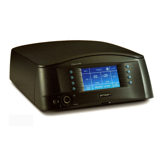
7.1 DESCRIPTION OF THE APPARATUS 7.1.1 DISPLAY The CRYO-LINE unit is equipped with an LCD display which displays the most important operation data of system (Pressure, Temperature, Application time), the alarms and the data defined by the operator (Application Temperature, Application Time). Using the two rows of buttons located on the sides of the display, it is possible to activate and deactivate the functions of the instrument. -
Page 24: Application Time Control
CRYO-LINE Manual for installation and use OPTIKON 2000 The temperature control occurs when the relative procedure (TEMP CTRL) is activated by pressing the key next to the symbol on the display. In this state, pressing the footswitch activates the freezing procedure of the probe until the set temperature is reached. -
Page 25: Configuration Of The Unit
CRYO-LINE Manual for installation and use OPTIKON 2000 7.2 CONFIGURATION OF THE UNIT This section contains information on the configuration of the unit. All the operational controls adjustments identified described below. The connectors and other elements of the instrument are described in Figure 1. The connectors of the rear panel and other elements are described in Figure 2. - Page 26 This is the port for the connector of the footswitch that, when pressed, activates the functions of the CRYO-LINE unit. 6) SERIAL CONNECTOR This connector allows to connect the CRYO-LINE unit to a PC through a serial connection. This connector is used for technical servicing of the instrument. 7) EQUIPOTENTIALITY CONNECTION Connector for the verification of the zero potential of the instrument.
-
Page 27: User Interface
Manual for installation and use OPTIKON 2000 7.3 USER INTERFACE The user interface of the CRYO-LINE unit consists in a backlit LCD display and 8 buttons located on the sides of the display. Figure 3. Display Graphics The graphics of the display have been divided into functional areas: System information for the user 1) System state and error messages. -
Page 28: Sound Messages
For this reason, the CRYO-LINE unit is equipped with an audio frequency synthesizer that can generate suitable sounds. The sound messages are associated with: 1. -
Page 29: User Interface
CRYO-LINE Manual for installation and use OPTIKON 2000 8. USER INTERFACE 8.1 LANGUAGE SELECTION Approximately three seconds after turning on the instrument it is possible to access the language selection interface by pressing one of the silicone buttons on the front panel. -
Page 30: Application Time Control
CRYO-LINE Manual for installation and use OPTIKON 2000 4. To freeze the tip of the probe (Freezing), press the footswitch connected to the instrument. When the footswitch is pressed, the timer activates to count the time of application. 5. To defrost the tip of the probe (Defrosting), release the footswitch connected to the instrument. -
Page 31: Application Temperature Control
CRYO-LINE Manual for installation and use OPTIKON 2000 NOTE Screw the probe connector onto the console until it is fully tightened. 3. Wait for the probe cleaning phase (Purge) to finish before beginning the surgical procedure. The end of the purge phase is accompanied by a sound signal. - Page 32 CRYO-LINE Manual for installation and use OPTIKON 2000 CAUTION This type of procedure works only with cryosurgical probes equipped with a thermocouple. The use of inappropriate probes may cause damage to the system and the patient. Operation 1. Select a cryosurgical probe 2.
-
Page 33: System Test
5. Insert a cryosurgical probe into the probe connection. 6. If operations 1-5 have been carried out properly, start the circuit test. 7. If one of these tests fails, contact the service centre or your Optikon distributor. Code 131002 EN... -
Page 34: Shutdown Procedure
OPTIKON 2000 8.6 SHUTDOWN PROCEDURE NOTE If the Cryo-Line surgical system is not used for an extended period, follow the procedure described below. 1) Press the “POWER” switch to turn off the console. 2) Close the valve on the cylinder or the centralized system outlet. -
Page 35: Cleaning, Sterilization And Maintanence
For the cleaning, decontamination and sterilization of reusable surgical instruments of the CRYO-LINE device, consult their respective user instructions. The console, footswitch and cart cannot be sterilized but can be cleaned according the instructions provided below. -
Page 36: Sterilization
9.3 MAINTENANCE 9.3.1 UNIT 1) Store the CRYO-LINE cryosurgery system in a clean dry location at room temperature. 2) After use, disconnect the hose of the cylinder. 3) Periodically replace the cylinder filter. 4) To maintain optimal performance for the entire life of the equipment, an annual maintenance and calibration program must be defined. - Page 37 CRYO-LINE Manual for installation and use OPTIKON 2000 CAUTION 1) Do not use synthetic detergents or oil-based soaps. 2) Make certain that the probe’s console connector is completely dry before using it; any humidity present may compromise the freezing efficiency.
- Page 38 CRYO-LINE Manual for installation and use OPTIKON 2000 THIS PAGE HAS BEEN INTENTIONALLY LEFT BLANK Code 131002 EN 2014-02-06 Rev.F...
-
Page 39: Troubleshooting Guide
10.1 WARNINGS AND ERROR MESSAGES On the LCD display, the CRYO-LINE unit displays warnings and error messages to inform the operator of situations the may require special attention. The code and relative meaning of the error appear in the top centre part of the LCD display. -
Page 40: Miscellaneous Problems
Defective valve. Call the Optikon technical service. Leak from the probe Defective probe. Send the probe to Optikon for repair. 10-2 Code 131002 EN 2014-02-06 Rev.F... - Page 41 High pressure. Do not use the instrument in this condition. Check the type of gas used or the operating Err 06 pressure of the system to which the OPTIKON Cryo- Line is connected. Low pressure. Do not use the instrument in this condition.
- Page 42 CRYO-LINE Manual for installation and use OPTIKON 2000 THIS PAGE HAS BEEN INTENTIONALLY LEFT BLANK 10-4 Code 131002 EN 2014-02-06 Rev.F...
-
Page 43: Accessories
CRYO-LINE Manual for installation and use OPTIKON 2000 11. ACCESSORIES 11.1 RECOMMENDED ACCESSORIES CODE DESCRIPTION PICTURE 183001 Instrument cart with cylinder holder 11-1 Code 131002 EN 2014-02-06 Rev.F... -
Page 44: Available Cryosurgical Probes
CRYO-LINE Manual for installation and use OPTIKON 2000 11.2 AVAILABLE CRYOSURGICAL PROBES CODE DESCRIPTION PICTURE 133001 Cataract cryosurgical probe 133002 Retina cryosurgical probe, spherical 133003 Retina cryosurgical probe, spatula 133004 Retina cryosurgical probe, “T” 133005 Retina cryosurgical probe, “Bonnet” 133006... -
Page 45: Spare Parts
CRYO-LINE Manual for installation and use OPTIKON 2000 11.3 SPARE PARTS NOTE The maintenance operations that can be carried out by the user must be limited to the replacement of the parts listed below. The warranty will not be considered valid if work is carried out on any other part. - Page 46 CRYO-LINE Manual for installation and use OPTIKON 2000 THIS PAGE HAS BEEN INTENTIONALLY LEFT BLANK 11-4 Code 131002 EN 2014-02-06 Rev.F...
-
Page 47: Index
CRYO-LINE Manual for installation and use OPTIKON 2000 12. INDEX Application time control ....8-2 Maximum cylinder pressure .... 3-1 Backlit lcd display ......7-3 Nitrogen Protoxide evacuation ..3-2 Current consumption ....5-2 Probe cable winding ..... 3-2 Cylinder securing ......3-1 Purification of the probe ....
Need help?
Do you have a question about the CRYO-LINE and is the answer not in the manual?
Questions and answers