Table of Contents

Subscribe to Our Youtube Channel
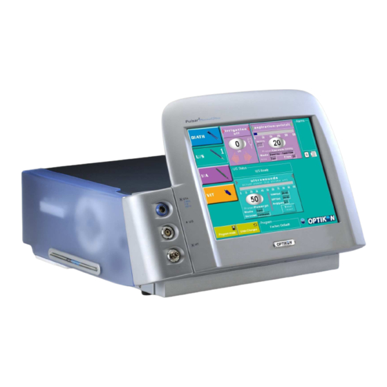
Related Manuals for OPTIKON PULSAR 2


Summary of Contents for OPTIKON PULSAR 2
- Page 1 Cod. 111004S - Rev. D PULSAR SURGERY SYSTEM SERVICE MANUAL OPTIKON 2000 S.p.A. Via del Casale di Settebagni, 13 - 00138 Rome Italy Phone +39 06 8888355 - Fax. +39 06 8888440 e-mail mailto:sales@optikon.com - www.optikon.com...
- Page 2 Optikon 2000 SpA is an ISO 9001 and ISO 13485 certified company which manufactures surgical and diagnostic devices for ophthalmology. Its products are manufactured to satisfy the requirements of 93/42/EEC Medical Devices Directive.
-
Page 3: Table Of Contents
TABLE OF CONTENTS DISCLAIMER ............ 1-1 TECHNICAL SPECIFICATIONS ........ 2-1 2.1 DIATHERMY POWER CHARACTERISTICS........2-5 WARNINGS ............3-1 GENERAL INFORMATION ........4-1 4.1 EQUIPMENT LAYOUT ............4-1 4.1.1 FRONT VIEW (FIG.1) ..............4-1 4.1.2 LEFT SIDE VIEW (FIG. 2) ............... 4-2 4.1.3 REAR PANEL (FIG. - Page 4 THIS PAGE IS INTENTIONALLY BLANK...
-
Page 5: Disclaimer
Pulsar Service Manual OPTIKON 2000 1. DISCLAIMER OPTIKON 2000 S.p.A. requires the user of this system to carefully read specific warnings found in this manual. Optikon 2000 S.p.A. declares to be liable for safety, reliability and performance only if: • upgrades, calibrations, repairs are carried out by OPTIKON 2000 S.P.A. - Page 6 Pulsar Service Manual OPTIKON 2000 THIS PAGE IS INTENTIONALLY BLANK Cod. 111004SEN Rev.C...
-
Page 7: Technical Specifications
Pulsar Service Manual OPTIKON 2000 2. TECHNICAL SPECIFICATIONS PARAMETER SPECIFICATION Manufacturer:....... OPTIKON 2000 S.p.a. via del Casale di Settebagni, 13 00138 Rome - Italy Model: ........ PULSAR Regulatory compliance: ..93/42/EEC Medical Devices Directive (MDD) Technical standards: ....EN 60601-1 ; EN 60601-1-1 ;... - Page 8 Pulsar Service Manual OPTIKON 2000 PARAMETER SPECIFICATION Flow: ......... at least 30 normal litre/minute @ 500mmHg Default vacuum level: ..... user programmable Available vacuum range: ..5 to 500 mmHg Default flow rate: ....user programmable Available flow rate range: ..
- Page 9 Handpiece type: ....bipolar microforceps, slim stat pencil eraser, intraocular diathermy pencils Diathermy cable: ....poles, gauges, ohm, steam autoclavable. Use only original OPTIKON 2000 S.P.A. diathermy cable Control: ......system footswitch PHACOEMULSIFIER Handpiece type: ....piezoelectric Frequency: ......approx. 40KHz Tip stroke: ......
- Page 10 Pulsar Service Manual OPTIKON 2000 IEC 60601-1 EQUIPMENT CLASSIFICATION ACCORDING TO Type of protection against electric shock: ...... class I Degree of protection against electric shock: Diathermy: ......Type BF, floating both at high and low frequencies U/S: ........Type B Degree of protection against harmful ingress of water (unit) : .
-
Page 11: Diathermy Power Characteristics
Pulsar Service Manual OPTIKON 2000 2.1 DIATHERMY POWER CHARACTERISTICS ANTARES PULSAR DIATHERMY POWER vs LOAD 100 150 200 250 300 350 400 450 500 550 600 650 700 750 Preset=100% Preset=50% Diathermy Power vs load ANTARES PULSAR DIATHERMY POWER vs PRESET... - Page 12 Pulsar Service Manual OPTIKON 2000 THIS PAGE IS INTENTIONALLY BLANK Cod. 111004SEN Rev.C...
-
Page 13: Warnings
OF PUBLICATION, BUT IS PROVIDED WITHOUT WARRANTY OF ANY KIND AND WE ASSUME NO RESPONSIBILITY WITH RESPECT THERETO. 1) SERVICE AND REPAIR OF THE SYSTEM SHOULD BE RESTRICTED QUALIFIED TECHNICAL PERSONNEL AUTHORIZED BY OPTIKON 2000. 2) THE "OPTIKON PULSAR " CONTROL CONSOLE IS PROVIDED WITH A VOLTAGE CHANGER. - Page 14 Pulsar Service Manual OPTIKON 2000 THAT ARE NOT PROTECTED BY RESISTORS OR HIGH FREQUENCY INDUCTORS SHOULD BE PLACED AS FAR AWAY AS POSSIBLE FROM THE DIATHERMY ELECTRODES. 13) THE CABLE OF THE BIPOLAR DIATHERMY HANDPIECE SHOULD NOT TOUCH THE PATIENT OR OTHER CABLES.
- Page 15 Pulsar Service Manual OPTIKON 2000 29) HANDPIECES AND OTHER NON DISPOSABLE ACCESSORIES ARE SUPPLIED NON STERILE. THEY MUST BE FIRST CLEANED, THEN STERILIZED IN AUTOCLAVE AS INDICATED ON THE RELATIVE INSTRUCTIONS. THEY COULD BE DAMAGED BY THE USE OF OTHER STERILIZATION METHODS, LIKE HOT AIR OR "CHEMCLAVE"...
- Page 16 Pulsar Service Manual OPTIKON 2000 THIS PAGE IS INTENTIONALLY BLANK Cod. 111004SEN Rev.C...
-
Page 17: General Information
Pulsar Service Manual OPTIKON 2000 4. GENERAL INFORMATION 4.1 EQUIPMENT LAYOUT This section contains information on the equipment layout. All operating controls and adjustments are identified and described further on. Sockets and other elements on the front panel are described in Fig. 1 Left side (pump side) of the instrument is described in Figure 2. -
Page 18: Left Side View (Fig. 2)
It also prevents sudden vacuum surges, thus stabilizing the anterior chamber. 4) PERISTALTIC PUMP This pump allows peristaltic aspiration in the PULSAR 2. The pump rotor is automatically moved vertically to allow tubing installation and/or Venturi aspiration. 5) WASTE COLLECTION TANK SUPPORTS These two brackets support and hold in place the waste collection rigid tank at the end of the aspiration path. -
Page 19: Rear Panel (Fig. 3)
Pulsar Service Manual OPTIKON 2000 4.1.3 REAR PANEL (FIG. 3) 1) COOLING FAN Removes hot air from the unit. CONNECTOR FOR VIDEO OVERLAY This connector makes it possible the connection to the "Eclipse" Video Overlay device, which allows you to superimpose the main parameters on the video shot during surgery. - Page 20 This is the discharge valve for the humidity condensed in the gas filter. Gently depress the valve to evacuate water from the filter polycarbonate container. 12) I.V. POLE CONNECTOR This connector provides a direct interface to the OPTIKON AUTOMATIC I.V. POLE. 13) POWER (ON/OFF MAINS SWITCH ASSEMBLY) The power switch is used to switch on/off the unit.
-
Page 21: Internal View (Fig.4)
Pulsar Service Manual OPTIKON 2000 4.1.4 INTERNAL VIEW (FIG.4) 1 ) SENSORS BOARD This board hosts the “External” pressure sensor monitoring pressure at the output of the primary regulator (for the “Low Pressure” alarm), the electronics for the vacuum sensor. - Page 22 Pulsar Service Manual OPTIKON 2000 This connector allows monitoring the air pressure at the output of the main pressure regulator. To remove the red plug (occluder), push down the black ring around the base of the plug while pulling this out.
-
Page 23: Side Plate
Pulsar Service Manual OPTIKON 2000 4.1.5 SIDE PLATE 1) CONNECTION TO VENTURI PUMP The silicone tube from the Venturi pump connects to this tube holder. The disposable cassette tank connects at the other side of the tube holder. 2) VACUUM SIGNAL FILTER (369130000) This is the vacuum sensor and amplifier/filter board for closed system vacuum reading in the disposable cassette. - Page 24 Pulsar Service Manual OPTIKON 2000 6) WATER LEVEL I.R. SENSOR This Infra Red emitter and sensor detects the presence of the I/A waste collection cassette and the water level in it. 7) REFLUX VALVE When the plunger of this soleneoid valve retracts, the aspiration line is put in communication with the irrigation line from the drip chamber.
-
Page 25: Under The Monitor
Pulsar Service Manual OPTIKON 2000 4.1.6 UNDER THE MONITOR 1) LVDS RECEIVER MODULE FOR TFT DISPLAY (391140000) The LVDS receiver decodes the LVDS video signals from the PC board translating them in TTL signals to drive the TFT LCD. 2) TOUCH SCREEN CONTROLLER BOARD (391160000) This board provides interface between the touch screen and the PS2 input of the PC board. - Page 26 Pulsar Service Manual OPTIKON 2000 1) PC BOARD This board is an embedded PC system that includes all the peripherals (RS232, USB, LPT, VGA, PS2, etc.) which are necessary for the GUI. 2) SOLID STATE HARD DISK (DOM) (391170000) The solid state HD contains all the Graphic User Interface software; this includes the operating system, the graphic control software, the user settings (programs) and other configuration parameters.
-
Page 27: Principles Of Operation
OPTIKON 2000 5. PRINCIPLES OF OPERATION 5.1 INTRODUCTION The OPTIKON PULSAR is a state of the art system designed for cataract extraction. The use of a multiple microprocessor architecture combined with some Large Scale Integration circuits (LSI), allows concentrating high technology and top performances in a small and compact unit. - Page 28 Pulsar Service Manual OPTIKON 2000 Cod. 111004SEN Rev.C...
- Page 29 Pulsar Service Manual OPTIKON 2000 Cod. 111004SEN Rev.C...
- Page 30 Pulsar Service Manual OPTIKON 2000 Cod. 111004SEN Rev.C...
- Page 31 Pulsar Service Manual OPTIKON 2000 Cod. 111004SEN Rev.C...
-
Page 32: Control Board 393200
Pulsar Service Manual OPTIKON 2000 5.2 CONTROL BOARD 393200 The 393200 Control board schematics have been logically divided in five sheets: 1. Sheet contain logic part board: - The main microprocessor 18F6520 with its reset circuitry. The 18F6520 is a powerful single chip processor produced by Microchip. -
Page 33: Graphic User Interface
Pulsar Service Manual OPTIKON 2000 a square wave of variable duty cycle is output, the higher is the duty cycle the optocoupler that higher will be the pump speed. The square wave is applied to U19 replicates the same waveform at the input of U18B (U19 allows to maintain electric separation between GNDs and GNDp). - Page 34 Pulsar Service Manual OPTIKON 2000 Cod. 111004SEN Rev.C...
- Page 35 Pulsar Service Manual OPTIKON 2000 Cod. 111004SEN Rev.C...
- Page 36 Pulsar Service Manual OPTIKON 2000 5-10 Cod. 111004SEN Rev.C...
- Page 37 Pulsar Service Manual OPTIKON 2000 5-11 Cod. 111004SEN Rev.C...
- Page 38 Pulsar Service Manual OPTIKON 2000 5-12 Cod. 111004SEN Rev.C...
- Page 39 Pulsar Service Manual OPTIKON 2000 Notes: On solderings side, 1- Solder a 10K 1/4W resistor between Pin2 and 6 of U21 2- Solder a 100K 1/4W resistor in parallel to D14 3- Pulsar , do not mount Q8 and short circuit collector and emitter...
-
Page 40: U/S Driver 347150
Pulsar Service Manual OPTIKON 2000 5.4 U/S DRIVER 347150 INTERFACE TO 393200 INTERFACE TO 369140 CONTROL LOGIC ADJUSTABLE DIATHERMY ULTRASOUND POWER SUPPLY The operating philosophy of the U/S Driver 347150 is shown by the block diagram above. The board contains both the U/S driver and the Diathermy driver, they share the same adjustable power supply and they are both controlled by the same microprocessor (NEC’s 78F0078). - Page 41 Pulsar Service Manual OPTIKON 2000 signal. This quick response enables the microprocessor, that controls the VCO, to dynamically correct possible changes, due to changes in the load, of the handpiece resonating frequency. Piezo handpiece is connected to J1 card connector and is driven by a sinusoidal voltage of variable frequency and amplitude.
- Page 42 Pulsar Service Manual OPTIKON 2000 The CR3, C66 and CR4, C69 components limit the peak voltage upon switching. The signals controlling the MOSFET U5 driver are two square waves of opposite phase picked up from PLD ( Programmable Logic Device) U10 ( DRV1 and DRV2 signals).
-
Page 43: Diathermy Driver Section (Sheet 2/2)
Pulsar Service Manual OPTIKON 2000 Reference voltage Vb can be varied by the microprocessor by the means of DAC U3. The information conveyed by micro to DAC U3 is determined by the means of a patented electronic circuit named “Minimal Stress” (ESS module in the schematics). - Page 44 Pulsar Service Manual OPTIKON 2000 U8C and U8D are used as gates to apply the two square waves to the MC3452 (U16) MOSFET driver only when the control signal ENDIA, from the microprocessor, is low (0 Vdc). Two power MOSFET, Q4 and Q5, are operated by the MC3452 driver, their drain is connected to the primary winding of L5 which provides insulation from the part applied to the patient.
- Page 45 Pulsar Service Manual OPTIKON 2000 5-19 Cod. 111004SEN Rev.C...
- Page 46 Pulsar Service Manual OPTIKON 2000 5-20 Cod. 111004SEN Rev.C...
- Page 47 Pulsar Service Manual OPTIKON 2000 U/S & Diathermy driver 347150rev.J 5-21 Cod. 111004SEN Rev.C...
-
Page 48: Sensors Board 393120
Pulsar Service Manual OPTIKON 2000 5.5 SENSORS BOARD 393120 The 393120 Sensors board: contains: The circuitry of the pressure sensor (mounted on the board) used to monitor the output pressure of the primary regulator. The balanced output of the strain gauge sensor is voltage buffered by U1-A-B, then delivered to the differential amplifier U1-C. - Page 49 Pulsar Service Manual OPTIKON 2000 5-23 Cod. 111004SEN Rev.C...
- Page 50 Pulsar Service Manual OPTIKON 2000 5-24 Cod. 111004SEN Rev.C...
-
Page 51: Vacuum Signal Filter 369130
Pulsar Service Manual OPTIKON 2000 5.6 VACUUM SIGNAL FILTER 369130 This small board is assembled directly behind the 141PC15G vacuum sensor used to monitor the vacuum in the aspiration line (in the ACS3 system of the Dual Pump Disposable Cassette). The board and sensor assembly is located inside the PULSAR2, on the metal plate that supports the Disposable Cassette and the peristaltic pump. - Page 52 Pulsar Service Manual OPTIKON 2000 5-26 Cod. 111004SEN Rev.C...
-
Page 53: The Pulsar Power Board 391110
Pulsar Service Manual OPTIKON 2000 5.7 THE PULSAR POWER BOARD 391110 This board generates all the DC voltages needed by the PULSAR2 to operate. The 26Vac-3A secondary of the power transformer (protected by F3 5AT fuse) is rectified by D5 and clipped by Z1 to generate the Power Fail signal. It is also... - Page 54 Pulsar Service Manual OPTIKON 2000 5-28 Cod. 111004SEN Rev.C...
- Page 55 Pulsar Service Manual OPTIKON 2000 5-29 Cod. 111004SEN Rev.C...
-
Page 56: Checks And Calibrations
Pulsar Service Manual OPTIKON 2000 CHECKS AND CALIBRATIONS 6.1 POWER SUPPLY BOARD 391110 Disconnect all output cables from the board (J2, J4, J5). Connect the PULSAR2 to the mains and switch it on. Verify, with a digital voltage meter, the output voltages of the board on the... -
Page 57: The System Calibration Software
Pulsar Service Manual OPTIKON 2000 U/S adjustable power supply check Connect an Ultrasonic handpiece and tune it by depressing the footswitch beyond position #3, while keeping the tip in water. 1. Set MODE to SURGEON, connect an oscilloscope between TP8 and TP9 (GNDs) and preset U/S power to 100%. - Page 58 Pulsar Service Manual OPTIKON 2000 • Type in Quit Phaco <enter> The PULSAR2 will exit the normal working software and it will show the Windows CE desktop. • Double tap the Tools icon of “Calibrations” on the desktop. The System Calibration Software window will appear in the middle of the screen.
-
Page 59: Calibration Software Interface Description
Pulsar Service Manual OPTIKON 2000 6.4.1 CALIBRATION SOFTWARE INTERFACE DESCRIPTION The Calibration Software User interface is divided in seven frames: Mode frame. Allows selection of - Calibration mode - Lookup table construction The Calibration mode allows the various system calibrations described below, The Lookup table construction mode enables the automatic build up of a lookup table for the voltage vs. -
Page 60: External Pressure Sensor And Main Press.regulator Calibration
Pulsar Service Manual OPTIKON 2000 Restore Backup Restores all the user programs (settings) to the status before last change was done. This function can be used to restore programs which have been deleted or modified by mistake. Close Exits the Calibration tool service program. -
Page 61: Secondary Pressure Regulator Calibration
Pulsar Service Manual OPTIKON 2000 6.4.3 SECONDARY PRESSURE REGULATOR CALIBRATION The secondary pressure regulator (Fig.4, ref.5) adjusts the output pressure for the pneumatic vitreous cutter and microscissors. This calibration is performed in Vitrectomy mode. 1. Connect a pressure gauge (at the least 5bar, 72.5PSI full scale) to the Vit output. -
Page 62: Vacuum Sensor Calibration
Pulsar Service Manual OPTIKON 2000 6.4.5 VACUUM SENSOR CALIBRATION This sensor monitors the vacuum level in the aspiration line connected to the surgical handpiece. DO NOT INSTALL THE I/A TUBING for this calibration. NOTE: select “Calibration” in the “Mode” frame! 1. -
Page 63: Peristaltic Pump Flow Calibration
Pulsar Service Manual OPTIKON 2000 6.4.7 PERISTALTIC PUMP FLOW CALIBRATION Mount around the peristaltic pump the appropriate measuring set, run the section of tube from the rear side of the pump to a graduated cylinder positioned at the same level of the equipment, dip the tube from the front slot of the peristaltic pump in a container filled with water. - Page 64 Pulsar Service Manual OPTIKON 2000 3. VENTURI PUMP AND VALVES Select I/A mode, install the I/A tubing, select Venturi aspiration mode and a vacuum of 100mmHg or more. Verify that: Irrigation valve (close to the front of the equipment) is activated (de- energized) at switch #1 of the footswitch.
- Page 65 Pulsar Service Manual OPTIKON 2000 ELECTRIC I.V. POLE (if available) Switch the PULSAR2 off, conne ct the electric I.V. pole cable to the rear panel connector. Switch the equipment (and the cart) on. Verify that the PULSAR2 tests the pole moving it slightly up and down.
-
Page 66: Touch Screen Calibration
Pulsar Service Manual OPTIKON 2000 6.5 TOUCH SCREEN CALIBRATION The User can input commands to the ASSISTANT GUI through its resistive touch screen. If the touch screen, with the monitor frame, is replaced or if the PC board is replaced, it may be necessary to recalibrate the touch screen. -
Page 67: Troubleshooting
Pulsar Service Manual OPTIKON 2000 7. TROUBLESHOOTING 7.1 WARNING AND ERROR MESSAGES The PULSAR console delivers warning and error messages on the LCD to inform the operator of situations which may require special attention. A window pops up in the middle of the LCD giving full explanation of the warning or error, if operation can continue, an OK button appears on the window. - Page 68 Pulsar Service Manual OPTIKON 2000 Understanding the meaning of the above error messages may help in troubleshooting PULSAR malfunctions. • Err 01: Serial comunication fault The User interface software checks the correct serial communication between the 391130 PC board that controls the graphic interface and the 393200 Control board controlling the surgical functions of the equipment.
- Page 69 Pulsar Service Manual OPTIKON 2000 with the standard software enable/disable and with the safety hardware disable. If a malfunction is found Err26 or Err27 are generated. This could be due to a malfunction of the 347888000 (347150) or to a missing connection between J10 of the Control board and J5 of the U/S and Diathermy driver.
- Page 70 The handpiece and/or tip have not been properly cleaned before sterilization. b) The aspiration line is bent or occluded. c) The tip used is a high-vacuum low-flow non OPTIKON® tip. d) The equipment is not connected to the electric pole in the cart and the bottle is too low.
-
Page 71: Mains Supply Related Errors
Pulsar Service Manual OPTIKON 2000 • Err 15: Minor leakage Once the lines are completely filled with fluids, the Pulsar2 closes the irrigation valve to built 300mmHg of vacuum. If this level cannot be reached, there is a minor leakage in the I/A system: a) I/A connectors are not fully engaged in the handpiece connectors. - Page 72 Pulsar Service Manual OPTIKON 2000 OTHER ERRORS If the equipment is not used for long time (more than 3 months), the RTC/CMOS battery discharges partially and it may cause the equipment not to start normal operation at power on (screen remains black).
- Page 73 Pulsar Service Manual OPTIKON 2000 THIS PAGE IS INTENTIONALLY BLANK Cod. 111004SEN Rev.C...
-
Page 74: Available Spare Parts
Pulsar Service Manual OPTIKON 2000 8. AVAILABLE SPARE PARTS CODE DESCRIPTION 347888000 U/S and Diathermy driver Board 393200000 Pulsar2 Control Board 391110000 Pulsar2 Power supply board 393120000 Sensors board 369130000 Vacuum sensor board 391130000 PC board 391170000 Solid state HD (DOM) 64Mb...
Need help?
Do you have a question about the PULSAR 2 and is the answer not in the manual?
Questions and answers