Advertisement
Quick Links
FEBRUARY 2021
™
VesseLINK
Installation Guide for Certus 350 and Certus 200
This document contains technology controlled for export by the U.S. Department of
Commerce in accordance with Export Administration Regulations. Diversion contrary to
U.S. law prohibited.
COPYRIGHT © 2021
THALES DEFENSE & SECURITY, INC.
i
ALL RIGHTS RESERVED
Installation Guide 84464 Rev. E
COPYRIGHT © 2017
THALES DEFENSE & SECURITY, INC.
ALL RIGHTS RESERVED
Advertisement

Related Manuals for Thales VesseLINK Certus 350


Summary of Contents for Thales VesseLINK Certus 350
- Page 1 This document contains technology controlled for export by the U.S. Department of Commerce in accordance with Export Administration Regulations. Diversion contrary to U.S. law prohibited. COPYRIGHT © 2021 THALES DEFENSE & SECURITY, INC. ALL RIGHTS RESERVED Installation Guide 84464 Rev. E COPYRIGHT © 2017 THALES DEFENSE &...
- Page 2 RECORD OF CHANGES Date Description of Change Author Rev A July 2018 Initial Release SJacques Rev B Sept 2018 ECN 42140 SJacques Update based on Beta user feedback and testing Rev C Jan 2020 ECN 43090 SJacques Update includes mounting hardware kit corrections kbps Added 700...
- Page 3 Installation Guide 84464 Rev. E...
- Page 4 TABLE OF CONTENTS INTRODUCTION..................1-1 ......................... 1-1 NTRODUCTION ......................1-1 QUIPMENT VERVIEW Below Deck Unit (BDU) ..................... 1-2 Above Deck Unit (ADU) / Antenna ..................1-5 LINK K ..............1-6 ESSE ONTENTS AND CCESSORIES INSTALLATION ................... 2-1 ......................2-1 ENERAL UIDELINES ..............
- Page 5 1-1 T LINK S .............. 1-1 IGURE HALES ESSE YSTEM WITH CCESSORIES 1-2 B (BDU) ..................... 1-2 IGURE ELOW 1-3 B (BDU) LED ................... 1-3 IGURE ELOW 1-4 B (BDU) F ..............1-4 IGURE ELOW RONT ANEL ETAIL 1-5 B (BDU) B ..............
- Page 6 1-1 B (BDU) LED S ..............1-3 ABLE ELOW TATUS 1-2 S LINK C 350, L ......1-6 ABLE TANDARD ESSE ERTUS IST OF QUIPMENT 1-3 B LINK C 350, L ........1-7 ABLE ESSE ERTUS IST OF QUIPMENT 1-4 B 200, L ........
- Page 7 The Thales VesseLINK system should only be installed by a qualified professional installer of Maritime electronic systems. Improper installation could lead to system failure or could result in injury to personnel on board the vessel. The following are general safety precautions and warnings that all personnel must read and understand prior to installation, operation and maintenance of the VesseLINK system.
- Page 8 ANTENNA RADIATION HAZARDS To comply with FCC Radio Frequency radiation exposure limits, the antenna must be installed at a minimum safe distance as shown below. WARNING During operation, the antenna radiates high power at microwave frequencies that can be harmful to individuals. While the unit is operating, personnel should maintain a minimum safe distance from the antenna.
- Page 9 Certus 350 FCC Identifier: OKCVF350BM Contains FCC ID: OKCWROOM32U NOTE Certus 200 FCC Identifier: OKCVF200BM Contains FCC ID: OKCWROOM32U NOTE Changes or modifications not expressly approved by the authority to operate the equipment. Note: This equipment has been tested and found to comply with the limits for a Class B digital device, pursuant to part 15 of the FCC Rules.
- Page 10 Industry Canada Information Certus 350 Industry Canada: 473C-VF350BM Contains IC: 473C-WROOM32U NOTE Certus 200 Industry Canada: 473C-VF200BM Contains IC: 473C-WROOM32U NOTE Under Industry Canada regulations, this radio transmitter may only operate using an antenna of a type and maximum (or lesser) gain approved for the transmitter by Industry Canada. To reduce potential radio interference to other users, the antenna type and its gain should be so chosen that the equivalent isotropically radiated power (e.i.r.p.) is not more than that necessary for successful communication.
- Page 11 Installation Guide 84464 Rev. E...
- Page 12 Installation Guide 84464 Rev. E...
- Page 13 301-489-17. Effective and efficient use of radio spectrum in order avoid harmful interference is met by conforming to the ETSI EN 301-441standard. Manufacturer Thales Defense & Security, Inc. 22605 Gateway Center Drive Clarksburg, Maryland 20871 U.S.A. Place and Date Clarksburg,...
- Page 14 After initial start-up, for more detailed operational procedures, refer to the VesseLINK User Manual (Document # 84469) located on the Thales website and also accessible through the BDU Management Portal.
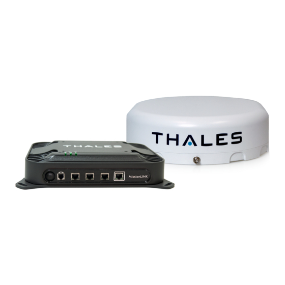
- Page 15 The Below Deck Unit (BDU) supports voice and data communications in a marine environment. The BDU is capable of supporting wireless voice and data that links the user with the Iridium satellite network. As a wireless access point, the BDU provides Wi-Fi (802.11) access for data and Voice over IP (VoIP) calls.
- Page 16 The BDU has three status LEDs on the top of the unit that indicate status of system power-up, satellite connection and the Wi-Fi. Indicator Description System Solid GREEN System functioning properly Flashing GREEN System busy (Booting up) Solid RED Fault (minor issue) Flashing RED Critical fault (major issue) Satellite...
- Page 17 The BDU front panel (left to right) has a main power button, one RJ-14 jack for POTS (Plain Old Telephone Service) Phone(s), three PoE (Power over Ethernet) RJ-45 connections for VoIP phones or Ethernet-based devices, and one WAN (Wide Area Network) connection primarily used to connect an external cellular modem or VSAT.
- Page 18 The Above Deck Unit (ADU) or Antenna is a standalone unit that connects to the BDU through a single coaxial cable. DC power, RF transmit and receive signals, control data and GPS data are communicated between the ADU and BDU using this single coaxial cable. Installation Guide 84464 Rev.
- Page 19 The following tables list the kits available for purchase and their contents as well as accessories and spare parts that can be purchased separately. Part Number Description VF350BM Standard Kit, VesseLINK Certus 350** Part Number Description Kit, Below Deck Unit (BDU), Mounting 1100789-501...
- Page 20 Part Number Description VF350BM-1 Base Kit, VesseLINK Certus 350 Part Number Description 1600901-1 Above Deck Unit / Antenna, Certus 350 3402131-1 Quick Start Guide (QSG) VesseLINK 3900011-1 Mounting Template, BDU 3900014-1 Mounting Template, Antenna 4102947-511 BDU VesseLINK 85728-001 Wi-Fi Antenna, 2.4 GHz Dipole 2 dBi...
- Page 21 Description Part Number 1100796-501 Thales SureLINK IP Handset Kit 1100818-501 Kit, Below Deck Unit (BDU), Mounting Hardware 1100789-501 Kit, Antenna Maritime Mounting Hardware (Certus 350 1100791-501 only) Mounting Template, BDU 3900011-1 Mounting Template, Antenna (Certus 350 only) 3900014-1 Power Supply, AC/DC 12V 160W...
- Page 22 3. Conduct an inventory of all components and parts using the equipment packing list provided with the equipment. Any missing items and/or shipping damage should be reported immediately to Thales Customer Service Department (Tel: (800) 324-6089 or email customer.service@thalesdsi.com). Installation Guide 84464 Rev. E...
- Page 23 The following steps should be followed to prevent damage to the equipment: 1. Keep dust cover over the SIM Card, once installed. 2. Do not disassemble or modify parts in installation kit unless instructed to do so. 3. Keep mounting hardware covered and protected until needed. Stay minimum distance indicated in the SAFETY section from the antenna when powered on.
- Page 24 Installation Guide 84464 Rev. E...
- Page 25 Distance d = 2.0m for S-Band up to 50kW d = 4.0m for X & C-Bands up to 50kW Installation Guide 84464 Rev. E...
- Page 26 NOTE The Certus 350 VesseLINK antenna is designed to fit the two optional Thales stainless steel antenna mounting kits (see Table 1-5). These pole mount kits contain instructions and all the hardware necessary for installation of the antenna. If replacing an existing L-band system, it may be possible to use the mounting plate and hardware that is already in place.
- Page 27 Installation Guide 84464 Rev. E...
- Page 28 The Antenna Mounting Template is provided in Appendix A for use in fabricating a custom plate. A mounting plate is not included in the kit, but Thales offers two pole mount brackets as NOTE accessory items. (Refer to Appendix C.) The antenna is mounted with either four M6 (torque to 6 N*m (4.4 ft.-lbs.)) or four M10 (torque...
- Page 29 Mounting using M6 Hardware 1. Use the template information provided in Appendix A to create the appropriate hole pattern in the desired mounting surface for the chosen mounting hardware. Hole sizing and provided hardware are shown for through hole mounting as shown in Appendix A. User may mount antenna with other hardware at their discretion and own risk.
- Page 30 6. Assemble screws (1) with flat washers (3) and split lock washers (2) as shown in Figure 2-6 and torque to requirements. 7. Run coaxial cable to approximate location of the BDU. Item Description Part Number Number Screw, Button HD Socket Cap M6x1x20mm A4-70 SS 82771-001 Washer, Split M6 (DIN 127B) A4 L/W SS 71300-001...
- Page 31 Mounting Hardware Installation Kit (PN 1100791-501) may contain additional hardware spares. The quantity listed in the above table reflects what is required for installation. NOTE Mounting using M10 Hardware 1. Use the template information provided in Appendix A to create the appropriate hole pattern in the desired mounting surface for the chosen mounting hardware.
- Page 32 Item Description Part Number Number Screw, Button HD Socket Cap M10x1.5x25mm A4-70 82770-001 (ISO 7380) SS Screw, Button HD Socket Cap M10x1.5x30mm A4-70 82770-002 (ISO 7380) SS Washer, Split M10 MED L/W A4 (DIN 127B) SS 71302-001 Washer, Flat M10 (DIN 125) 71301-001 Anti-Seize Lubricant, Loctite C5A Paste 91383-001...
- Page 33 M18 nuts for mounting the antenna to a custom made plate or an available accessory kit from Thales. The Thales accessory pole mount kit part number is 1100855-501 Note: When making a custom mounting plate or drilling a hole in an existing plate, the hole should optimally be 19mm in diameter.
- Page 34 2-13 Installation Guide 84464 Rev. E...
- Page 35 The VesseLINK Below Deck Unit is designed for ease of installation with four corner mounting locations for direct mounting. Figure 2-11 and Table 2-3 show the Thales BDU mounting kit with part number 1100789-501. It is strongly recommended that the BDU be grounded to vessel ground or earth ground for added protection against surges and static discharge.
- Page 36 Item Description Part Number Number Screw Phil Pan HD 18-8 M6x1x20mm SS 82768-001 BLK Oxide Washer Split Lock M6 (DIN 127B) A4 SS 71304-001 BLK Oxide Washer Flat M6 6.4mm ID x 12mm OD x 71298-001 1.6mm THK SS BLK Oxide Nut Lock w/Nylon Insert M6x1 18-8 SS 75656-001 1.
- Page 37 BDU can be mounted in any orientation but for best performance, it is recommended that it is mounted horizontally with the Thales logo facing up. This will give the best NOTE protection against any spills or dripping water and allows for the best heat transfer.
- Page 38 d. Secure the SIM Card cover once the SIM Card has been locked into place to prevent moisture or dust intrusion. (Figure 2-14) 5. Connect the provided RF cable that goes to the antenna. The BDU should be grounded. Use a 14 AWG (or larger) ground wire to connect the BDU to earth ground during normal use.
- Page 39 The BDU has two power connections available: AC Operation: The external AC/DC supply (Part #: 84670-001) with power cord. (See Figure 2-15) To safely disconnect the BDU from the power source, unplug the unit from the power outlet. NOTE When installing the BDU, the power outlet should be near the BDU and be easily accessible.
- Page 40 Installations using the DC power cable (PN 855024-020) should use the red and black primary power wires as well as the yellow remote wire as the ON/OFF switching source. The BDU will turn OFF with the ignition switch when the yellow remote line is connected, so it is important to make that connection in the vessel if desired (see Figure 2-16).
- Page 41 Now that the system installation is complete, press the power button on the BDU. In Figure 2-18, LEDs from left to right are: System (Overall System Status), Satellite (Satellite Connection Status) and Wi-Fi (Wireless Network Status). Table 2-4 describes the LED states. 2-20 Installation Guide 84464 Rev.
- Page 42 Indicator Description System Solid GREEN System functioning properly Flashing GREEN System busy (Booting up) Solid RED Fault (minor issue) Flashing RED Critical fault (major issue) Satellite Solid BLUE Connected and passing data (over satellite) Solid GREEN System functioning properly Flashing GREEN Acquiring satellite Solid RED Fault (minor issue)
- Page 43 THIS PAGE INTENTIONALLY LEFT BLANK 2-22 Installation Guide 84464 Rev. E...
- Page 44 PROBLEM SOLUTION Flashing GREEN light indicates that it is acquiring the satellite. If it continues to flash for more than 5 minutes, check that the Satellite LED Flashing antenna has a clear view of the sky. GREEN Reboot BDU. Critical Fault Detected. Open Management Portal http://portal.thaleslink (or https://portal.thaleslink) and check Alerts.
- Page 45 PROBLEM SOLUTION You may need to clear your browser cache. Ensure Terminal Unit is powered ON Ensure Wi-Fi is enabled and connected to ThalesLINK (or renamed SSID). If using a Wi-Fi enabled device, the Wi-Fi LED on the BDU should be solid GREEN. If not using Wi-Fi, ensure Cat 5 cable is connected to one of the three Ethernet ports (NOT WAN or POTS Port).
- Page 46 PROBLEM SOLUTION Check signal bars at the top of the Management Portal. If no bars are highlighted, the satellite is not being detected. Wait a few minutes to see if the signal strength improves as another satellite comes into view. Check antenna connection at the BDU and antenna.
- Page 47 PROBLEM SOLUTION Check LED status on BDU or on Management Portal. Make sure there are no RED LEDs. Check for Alerts in Management Portal by selecting the Alerts menu item Reboot the system and recheck for any Alerts that may have been generated.
- Page 48 Description Parameters Technical Uplink (TX) 1616 to 1626.5 MHz Frequency of Operation Downlink (RX) 1616 to 1626.5 MHz FDMA spacing 41.667 KHz Channelization TDMA Timing 8.3ms Slot in a 90ms window Channels Available 240 channels Certus 200 Certus 350 Voice 9 dBW 9 dBW Data Certus 2xC8 QPSK...
- Page 49 Environmental Description Certus 200 Certus 350 Operating Temp -30°C to +55°C IP Rating IP67 Operating Temp -30°C to +55°C IP Rating IP31 Mechanical Certus 200 Certus 350 5" D x 5.5" H 14.5" x 7.8" Dimensions (12.5 cm x 14 cm) (36.8cm x 19.8cm) Weight 1 lb.
- Page 50 The DB-15 connector with Pin out shown in Figure 4-1. See User Manual for more details. Pin No Name Description GND1 Ground Audio_In + Radio Gateway functionality, differential (+) Hi-Z Audio Input from external Radio Audio_Out + Radio Gateway functionality, Differential (+) Low-Z Audio Output to external radio (mic input) RadioCOR Radio Gateway functionality, Radio initiated voice into terminal...
- Page 51 Type: KPPX-4x connector (or similar) shown in Figure 4-2. Type: 684M7W2103L201 connector (or similar) shown in Figure 4-3. A1 = V+ /10-32VDC A2 =V- /GND Pin 5 = Ignition Installation Guide 84464 Rev. E...
- Page 52 Acronym Description Above Deck Unit Antenna Application Programming Interface Broadband Active Antenna Broadband Application Electronics Broadband Core Transceiver Below Deck Unit Terminal Unit Built In Test DTMF Dual Tone Multi-Frequency Enhanced Broadband ETSI European Telecommunications Standards Institute GPIO General Purpose Inputs/Outputs High Gain Antenna HRLP High Speed Radio Link Protocol...
- Page 53 Acronym Description Satellite Vehicle Transmission Control Protocol Terminal Unit User Datagram Protocol UL/DL Uplink/Downlink VLAN Virtual Local Area Network VOIP Voice of Internet Protocol Wide Area Network WI-FI Wireless Network WPA2-PSK Wi-Fi Protected Access 2 Pre-Shared Key Acronym Description Application Programming The Management Portal provides API to allow for the Interface connection to the terminal remotely.
- Page 54 Acronym Description Low Gain Antenna External antenna that connects to the BDU via a coaxial Certus Certus cable. The LGA supports 100 and 200 capabilities Management Management Portal: A web page served from the Portal Terminal Unit that brings together the diverse status and configuration information of the LMC 350 in one place.
- Page 55 THIS PAGE INTENTIONALLY LEFT BLANK Installation Guide 84464 Rev. E...
- Page 56 Acronyms / Glossary........................5-1 Connector Details BDU 10-32VDC Connector ..................... 4-4 BDU 12V Connector........................ 4-4 General Purpose Inputs/Outputs (GPIO) ................. 4-3 Equipment Overview ........................1-1 Installation Antenna Dimensions and Hole Pattern ..................2-6 Connecting Power to the BDU ....................2-18 General Guidelines........................
- Page 57 System Overview Above Deck Antenna Unit ....................... 1-5 Below Deck Unit (BDU) ......................1-2 Technical Specifications ......................4-1 Index-2 Installation Guide 84464 Rev. E...
- Page 58 Installation Guide 84464 Rev. E...
- Page 59 Installation Guide 84464 Rev. E...
- Page 60 An optional 316 stainless steel antenna mounting bracket is available. Antenna Pole Mount M6 (PN 85736-001)) Antenna Pole Mount M10 (PN 85739-001) The bracket is designed to work on standard 1.9-inch (with included bushing), 52mm and 3-inch poles (poles not included). This bracket has mounting holes that match the mounting points on the bottom of the antenna (M6 or M10).
- Page 61 Number Blue Loctite Apply to item 8, 9 S.S. Hub 52mm-ID for Metric 52mm Tube S. S. Bracket for Thales Antenna Nylon Bushing, ID.25, 24SW0250 S. S. Washer .275 x .5 x .062 S. S. Button Hd Bolt M6x20 Recommended Torque 8 Nm S.
- Page 62 Number Blue Loctite Apply to item 8, 9 , 12 S.S. Hub 52mm-ID fo Metric 52mm Tube S. S. Bracket for Thales Antenna Nylon Bushing, ID.25, 24SW0250 Plastic Reducer Bushing for S. S. Button Hd Bolt M6x20 Recommended Torque 6 Nm S.
- Page 63 Installation Guide 84464 Rev. E...
Need help?
Do you have a question about the VesseLINK Certus 350 and is the answer not in the manual?
Questions and answers