Table of Contents
Advertisement
Quick Links
Advertisement
Table of Contents

Subscribe to Our Youtube Channel
Related Manuals for FRANKLINWH aPbox


Summary of Contents for FRANKLINWH aPbox
- Page 1 Installation and Operations Manual Version 1.1 Issued on: December 22, 2022...
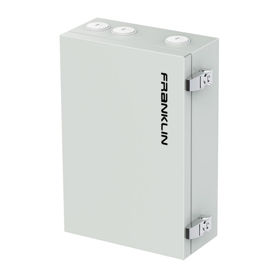
- Page 2 Product Information The FranklinWH aPbox provides the functions of an electrical meter and the ability to remotely disconnect from and connect to PV systems, controlled by the aGate X.
- Page 3 Installation and Operations Manual FCC Compliance This equipment has been tested and found to comply with the limits for a Class B digital device, pursuant to part 15 of the FCC Rules. These limits are designed to provide reasonable protection against harmful interference in a residential installation.
-
Page 4: Table Of Contents
PV on the line side of the FHP ........................... 10 aPbox Installation ............................. 11 Preparation ................................11 Installation ................................12 Unboxing ..............................12 Open the aPbox door .......................... 13 Cable Access ............................14 aPbox wall installation......................... 16 Wiring ..................................18 Make AC power connections ......................18 Communications connections ...................... - Page 5 Installation and Operations Manual aPbox Setting ................................. 26 Technical Support ............................. 28...
-
Page 6: Safety Statements
Safety Statements Important Information The FranklinWH aPbox is an electrical device. Please read this entire document to ensure proper use. Failure to follow this may void the warranty. Please strictly follow the safety instructions described in this manual during operation, otherwise it may result in equipment malfunction, electrical shock, serious injury or death. -
Page 7: Safety Instructions
It is strictly forbidden to install, maintain or handle aPbox units outdoors during bad weather such as thunder, rain, snow and high winds. It is strictly forbidden to work on or operate an aPbox alone. For safety, make sure that there is someone around you who can help. - Page 8 Installation and Operations Manual During the installation, use, storage, and transport of equipment: DANGER: Keep away from flammable and explosive materials. DANGER: Additional protective measures should be taken to protect equipment from access by children. WARNING: Install in dry, cool and well-ventilated location for satisfactory performance.
-
Page 9: Warranty Statement
To meet warranty requirements, FranklinWH aPbox products must be installed and operated properly according to the instructions in related FranklinWH documents. To secure the full warranty, the FranklinWH aPbox products must be reliably connected to Franklin Home Power (FHP) system to access remote services provided by FranklinWH. -
Page 10: Service And Maintenance
Installation and Operations Manual Service and Maintenance Service • Keep the equipment away from leaves or other foreign materials, especially keep objects from the top of the unit and keep the space clear between the unit and the back wall. -
Page 11: Product Overview
Installation and Operations Manual Product Overview The aPbox can be used to measure the amount of electricity generated by a PV system, and can also be used as a disconnect to sever the connection to the PV system when the photovoltaic over-generation is triggered. It supports access of up to two PV systems with a total current of no more than 65A. -
Page 12: Components
(Communications) • Control System: Consisting of a DC Power, a relay and a contactor, executing the command from the aGate X that allows the aPbox to disconnect from or reconnect to the PV system. • Metering System: Metering the PV production by a built-in meter and CTs. The CTs collect current data from the PV system and forward that data to the meter for analysis and reporting to the aGate X. -
Page 13: Application
While the aGate X has a PV breaker as an optional component, there are some situations in which the PV system cannot be connected through the breaker or where there are multiple PV connections needed. In those instances, an aPbox can be used to connect the solar source to the aGate X or the grid. -
Page 14: Pv On The Load Side Of The Fhp
Installation and Operations Manual PV on the load side of the FHP Installation of an aPbox is required to meter the production of and cutoff the connection to an individual PV system installed on the load side of the FHP system due to: •... -
Page 15: Pv On The Line Side Of The Fhp
Installation and Operations Manual PV on the line side of the FHP The installation of an aPbox is to monitor the generation of the PV system and provide data to the FHP system. In this scenario, one aGate X only supports one aPbox connection. -
Page 16: Apbox Installation
• Socket wrench, extension bar and 4pcs 1/4" expansion bolts The tools is for installing expansion bolts. • Torque wrench With various slotted screwdriver heads for mounting the aPbox on the wall connector cables and checking torque. • Torque wrench extension rod 6”... -
Page 17: Installation
Installation and Operations Manual Installation The length of the communications wire between the aGate X and the aPbox should not exceed 328 feet (100 meters). Unboxing Step 1 Inspect the packaging for damage. Step 2 Use a retractable utility knife to cut open the sealing tape of the package box, with the knife blade shorter than 0.3 inch to avoid damaging the aPbox case. -
Page 18: Open The Apbox Door
Installation and Operations Manual Open the aPbox door Use the key from the accessary bag to open the clasp locks, release the clas p and open the door, as shown in the following figure. Flip the door... -
Page 19: Cable Access
Cable Access Based on the preplanned installation position and electric conduit arrangements, choose which knockouts and plugs in the aPbox should be removed. Remove the plugs Open the door, then turn the selected plug nut counterclockwise by hand, until the n ut is removed. - Page 20 Installation and Operations Manual Remove the knockouts Step 1 Place a 1/4”X4” straight screwdriver against the black spot printed on the knockout hole, and then knock it with a hammer. Hammer until the knockout plug is angled out. Step 2 Using a needle-nose plier, twist the plug back and forth until the attachment points snap.
-
Page 21: Apbox Wall Installation
Step 1 Place the guide board at the planned installation position (refer to the local laws, regulations and codes for building construction to set the minimum height of aPbox). Use a spirit level to adjust the guide board, and then make marks at the four holes on the guide board. - Page 22 Step 4 Fasten the aPbox to the wall using the 1/4” water-tight washers (from the accessary bag), spring washers, and nuts in sequence. Use a torque wrench with an extension rod to check that the torque is 4.42 foot pounds.
-
Page 23: Wiring
Installation and Operations Manual Wiring DANGER Before wiring, check that all circuits to be connected to the aPbox are completely de-energized, and lock out any associated circuits breakers and disconnect switches. Make AC power connections NOTE • TB1 must be connected to the grid or an equivalent 240 Volt, 60Hz AC power source. - Page 24 Mark an appropriate length for later stripping. Step 2 Pull the wires out of the aPbox enclosure, cut off the wires from the marker point and strip the ends according to Table 1.
-
Page 25: Communications Connections
One aPbox connected to an aGate X When one unit is connected to an aGate X, the 485A and 485B terminals on the aPbox TB3 module are connected to the RS485 A1 and B1 terminals on the aGate X, respectively, DO+ and DO- terminals to the aGate DO terminals (without distinguishing the polarity) . - Page 26 Installation and Operations Manual 2)When one aPbox is installed on the line side of the FHP system, the communications wiring figure is as follows. Make sure the DO- and DO+ short connector of TB3 are reliably connected, otherwise the equipment will not work properly.
- Page 27 Installation and Operations Manual Two aPbox's connected to an aGate X One aGate X supports up to two aPbox connections on the load side of the FHP system. When two units are connected in parallel to an aGate X: •...
- Page 28 • Use twisted pair cables for RS485 conductors. • The DO- DO+ terminals of the two aPbox's should be connected in parallel. Make sure that they are not interchanged with one another. • When two units are connected to an aGate X, use 20AWG cables for...
-
Page 29: App Settings
Installation and Operations Manual App settings The aPbox works with the FranklinWH app. Keep the app up to date for normal operation. You can install the latest version of FranklinWH App from the Apple App Store and Google Play Store. - Page 30 Installation and Operations Manual Step 3 Click “Add Accessory” to add aPbox accessories. Step 4 Select "aPbox" from the drop-down box. Scan the device QR code or manually enter the "Serial number" and "Key", and click "Complete".
- Page 31 Installation and Operations Manual aPbox Setting Step 1 Click “Settings” to enter the Setting screen. Step 2 Click “Solar” to setting. Step 3 Input the proximal solar rated power value. Enable the Remote solar access feature before setting the Remote solar, then select the appropriate access mode according to the requirements.
- Page 32 Installation and Operations Manual Step 4 For both grid-side and load-side, input the solar power value. For load-side, also select the number of the connected solar systems. The following images show the different screens for the Grid-side and the Load-side access modes. Then click on Complete.
- Page 33 Please be prepared to provide the following information before you contact FranklinWH: • Owner name • Your preferred desired contact method (name, phone number, email) • The serial number of your aPbox (as shown in the figure below) • A brief description of your problem Serial number...
Need help?
Do you have a question about the aPbox and is the answer not in the manual?
Questions and answers