Table of Contents
Advertisement
Quick Links
Advertisement
Table of Contents

Related Manuals for Thinklogical Q Series

Summary of Contents for Thinklogical Q Series
- Page 1 ® High Reliability, Rack-Space Saving, Video Extension Solutions Q-Series Video Modules For use in the Q-4300, Q-2300 & Q-1300 Chassis Thinklogical, LLC ® 100 Washington Street Milford, Connecticut 06460 U.S.A. Telephone: 1-203-647-8700 Fax: 1-203-783-9949 www.thinklogical.com...
- Page 2 Copyright Notice Copyright Notice Copyright Notice Copyright Notice Copyright © 2014. All rights reserved. Printed in the U.S.A. Thinklogical, LLC ® 100 Washington Street Milford, Connecticut 06460 U.S.A. Telephone: 1-203-647-8700 All trademarks and service marks are property of their respective owners.
-
Page 3: Table Of Contents
Table of Contents PREFACE About Thinklogical Note and Warning Symbols 1. INTRODUCTION 1.1 Product Overview 2. SYSTEM FEATURES 2.1 General System Features 2.2 The Q-Series Chassis Line 3. THE Q-SERIES VIDEO SYSTEM 3.1. Types of Connectors 3.1.1. Fiber Cable 3.1.2. Transmitter 3.1.3. -
Page 4: Preface
PREFACE About Thinklogical Thinklogical is the leading manufacturer and provider of fiber optic KVM, video, audio, and peripheral extension and switching solutions used in video-rich, big-data computing environments. Thinklogical offers the only fiber optic KVM matrix switches and routers in the world that are accredited to The Common Criteria, EAL4 and TEMPEST. -
Page 5: Note And Warning Symbols
Note and Warning Symbols Throughout this manual you will notice certain symbols that bring your attention to important information. These are Notes and Warnings. Examples are shown below. Note: Important Notes appear in blue text preceded by a yellow exclamation point symbol, as shown here. -
Page 6: Introduction
Product Overview MRTS Technology 6.25 Gbps. allows for Full Frame Rate Transmission of uncompressed DVI or RGB video. Powered by Thinklogical’s cutting edge, patent-pending MRTS (Multi Rate Transmission ® System) Technology, our video extension systems transport every frame of a DVI or RGB video stream seamlessly with no compression or dropped frames. -
Page 7: System Features
Each module is hot swappable and, in addition, the standard SFP+ optics (with LC connectors) are hot swappable/hot pluggable. Every module is fully compatible with all of Thinklogical’s VXRouter line of products. 2.2 The Q-Series Chassis Line... -
Page 8: The Q-Series Video System
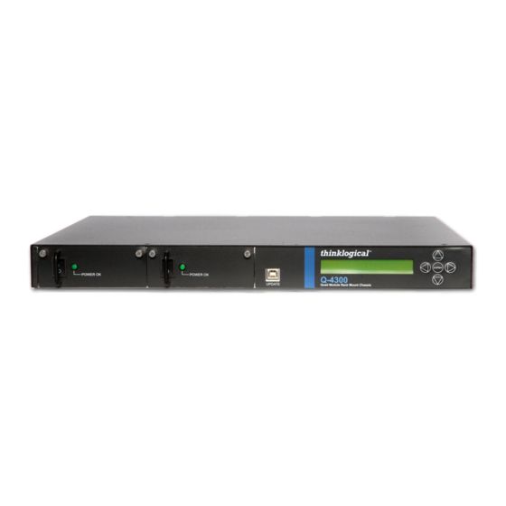
The Q-Series Video System 3.1. Types of Connections All physical connections to the product use industry-standard connectors. Non-supplied cables that may be needed are commercially available. All connections are found on the front panels of the modules. All models are connected via fiber optic cables (see paragraph 4.3. on page 17) to provide communications to and from the transmitter. - Page 9 Q-4300 Receiver Modules’ DDC OUT Displays Q-4300 Transmitter Modules’ Local Displays The VQM-3 Fiber Extension System- Up to 4 Single-Link DVI video signals can be extended in 1 RU Q-4300: Four VQM-3V Receiver Modules (VQM-00V003-LCRX) DVI Fibers: L1: Video & Data Tx to Rx L2: Data Rx to Tx Q-4300: Four VQM-3V Transmitter Modules...
- Page 10 Q-4300: 4 VQM-3R Redundant Receiver Modules (VQM-00R003-LCRX) Fiber Optic Cables: L1/L1': Video & Data Tx to Rx/ Video & DataTx to Rx' L2/L2': Data Rx to Tx/Data Rx to Tx’ Q-4300: 4 VQM-3R Redundant Transmitter Modules (VQM-00R003-LCTX) The VQM-3R Fiber Extension System- Up to 4 Single-Link DVI video signals can be extended in 1 RU with 4 Redundant Fiber Paths The VQM-6 Fiber Extension System- Up to 4 Single-Link DVI video signals can be extended in 1 RU Q - S e r i e s V i d e o M o d u l e s P r o d u c t M a n u a l , R e v .
- Page 11 Q-4300 (1) RX Network Device Module’s Destinations Source CPU 2 to Q-4300 (2) Active TX Module Network Vel- Active Vel- 3AN+ RX Network 3AN+ TX Module Vel- Module Vel- 3AN+ TX 3AN+ RX Module Module Q-4300 Q-4300 Stereo 3-D Coax IN Data Video Network...
-
Page 12: The Q-Series Video Modules
4. The Q-Series Video Modules This section lists the various DVI and RGB/DVI Modules designed to work with the Q- Series Video and Audio Extension System. Supported video formats include DVI and RGB/DVI single- link and dual-link. Models are also available with Audio (AV+, AH) and Network (AN+, NH) options. - Page 13 VQM-3V, TX VQM-3V, RX VQM-3R, TX VQM-3R, RX VQM-3 AV+ and VQM-3 AN+ Tx and Rx DVI Family of Modules: VQM-3 AV+, TX VQM-3 AV+, RX VQM-3V AV+, TX Q - S e r i e s V i d e o M o d u l e s P r o d u c t M a n u a l , R e v . H Page 13...
- Page 14 VQM-3V AV+, RX VQM-3R AV+, TX VQM-3R AV+, RX VQM-3 AN+, TX VQM-3 AN+, RX Q - S e r i e s V i d e o M o d u l e s P r o d u c t M a n u a l , R e v . H Page 14...
- Page 15 VQM-3V AN+, TX VQM-3V AN+, RX VQM-3R AN+, TX VQM-3R AN+, RX VQM-6, VQM-6 AV+ and VQM-6 AN+ Tx and Rx DVI Modules: (Pictured on page 15) VQM-6, VQM-6 AV+ and VQM-6 AN+ module features: • Supports all Single-Link and Dual-Link DVI video resolutions •...
- Page 16 VQM-6, TX VQM-6, RX VQM-6 AV+, TX VQM-6 AV+, RX VQM-6 AN+, TX VQM-6 AN+, RX Q - S e r i e s V i d e o M o d u l e s P r o d u c t M a n u a l , R e v . H Page 16...
-
Page 17: Velocity Q-Series Hdcp Compliant Video Modules
VQM-10 AV+ Tx and Rx RGB/DVI Modules: VQM-10AV+ module features: • Supports all Single-Link DVI and most common RGB video resolutions • MRTS technology 6.25Gbps allows for full frame rate transmission of uncompressed RGB/DVI • Signal transmission via fiber optic cable; no RF interference •... -
Page 18: Velocity Q-Series Hdcp Compliant Video Module Part Numbers
4.2.1. Velocity Q-Series HDCP Compliant Module Part Numbers: VQM-0H0003-LCRX VQM-3, Single Link DVI, DDC, HDCP Compliant, RX, LC VQM-0H0003-LCTX VQM-3, Single Link DVI, DDC, HDCP Compliant, TX, LC VQM-AH0003-LCRX VQM-3 AV+, Single Link DVI, DDC, Audio, Serial, HDCP Compliant, RX, LC VQM-AH0003-LCTX VQM-3 AV+, Single Link DVI, DDC, Audio, Serial, HDCP Compliant, TX, LC VQM-NH0003-LCRX... -
Page 19: Fiber Connections To The Q-Series Video Modules
The unit will operate with a single fiber from the TX to the RX. In this mode of operation the TX can transmit video and data to the RX over fiber L1. The RX cannot send any information to the TX. Also, DDC information can only be gathered from the TX local port or the Thinklogical default EDID table. -
Page 20: Two And Three Fiber Operation, Dual-Link Video
RX back to the TX. 4.4. Supplied Cables Depending on the customer-specified system configuration, power, video and peripheral cables from the following list will be supplied by Thinklogical in quantities specific to each configuration: 4.4.1 3.5mm to 3.5mm Audio Cable, 6 Feet (CBL000016-006FR) 3.5mm... - Page 21 4.4.5. BNC Male to Male, 50 , 6 Feet (CBL000018-006FR) 4.4.6. RJ45M to RJ45M CAT5, 2 Meters (CBL000001-002M) 4.4.7. VGA Male to DVI-A Male, 2 Meters (CBL000022-002MR) 4.4.8 . Domestic AC Power Cord (PWR-00006-R) 4.4.9. Adapters: RJ45 to DB9F (ADP-000025), RJ45 to DB9M (ADP-000019) RJ45 to RJ45 to DB9F ADPT...
-
Page 22: Dry Contact Alarm
4.5 Dry Contact Alarm Dry contact alarms are located on each of the individual modules. The relay is energized when there is an alarm condition, such as over temperature or power regulation. The dry contact alarm is a Form C contact with the following ratings: Nominal switching capacity: 1A, 30V DC Max. -
Page 23: Q-Series Video Modules Technical Specifications
4.7 Q-Series Video Modules Technical Specifications Module Specifications Power Consumption: 10 watts per unit VQM-3, VQM-3A, Dimensions: VQM-3N, VQM-3R, Height: 1.592” (40.43 mm) VQM-3H, VQM-3AH, Depth: 6.366" (161.69 mm) VQM-3NH,VQM-3V, Width: 3.693" (93.80 mm) VQM-3HV, VQM-AHV, (Tolerance: ± .039"; 1 mm) VQM-6, VQM-10AV+ Dimensions: VQM-3 AV+... -
Page 24: Status Indicator Leds
4.8 Status Indicator LEDs Q - S e r i e s V i d e o M o d u l e s P r o d u c t M a n u a l , R e v . H Page 24... -
Page 25: Firmware And Fpga Updates
4.9 Firmware and FPGA Updates Upgrades are available through Thinklogical . For technical assistance, please call us at: ® 1-203-647-8700. • To update the Chassis firmware, use the KM Download Procedure described below. Firmware Upgrade: USB Cable from CPU to UPDATE Port... -
Page 26: Regulatory & Safety Compliance
This is a Class A product. In a domestic environment this product may cause radio interference, in which case the user may be required to take adequate measures. European Union Declaration of Conformity Manufacturer’s Name & Address: Thinklogical, LLC ® 100 Washington Street Milford, Connecticut 06460 USA Telephone: 1-203-647-8700 These products comply with the requirements of the Low Voltage Directive 72/23/EEC and the EMC Directive 89/336/EEC. -
Page 27: Supplementary Information
Electromagnetic Immunity EN55024: 1998 Information Technology Equipment-Immunity Characteristics EN61000-4-2: 1995 Electro-Static Discharge Test EN61000-4-3: 1996 Radiated Immunity Field Test EN61000-4-4: 1995 Electrical Fast Transient Test EN61000-4-5: 1995 Power Supply Surge Test EN61000-4-6: 1996 Conducted Immunity Test EN61000-4-8: 1993 Magnetic Field Test EN61000-4-11: 1994 Voltage Dips &... -
Page 28: Connection To The Product
Monday through Friday from 8:30am to 5:00pm, Eastern Time Zone. We will ® try to respond to your email inquiries promptly, use the following email addresses for your different needs: info@thinklogical.com – Information on Thinklogical and our products. ® sales@thinklogical.com – Sales Department - orders, questions or issues. -
Page 29: Telephone
Defect remedy shall be the repair or replacement of the product, provided that the defective product is returned to the authorized dealer within a year from the date of delivery. If you wish to return your device, contact the Thinklogical, LLC authorized dealer where you purchased ®... -
Page 30: Return Authorization
Return Material Authorization. ® Our Address If you have any product issues or questions or need technical assistance with your Thinklogical system, ® please call us at 1-800-291-3211 (USA only) or 1-203-647-8700 and let us help. If you need to write us... -
Page 31: Appendix A: Quick Start Guides
QUICK-START GUIDE STEP 7: Connect the Controller Cards’ LAN Ports QUICK-START GUIDE STEP 1: Connect the Q-Series Receiver Modules to your Controller CPU with CAT5 cables. to the VX160 using multi-mode fiber-optic cables (CPU IP address: 192.168.13.9) (up to 1000 meters). Connect fiber to any SFP’s As used with the router... - Page 32 As used with Thinklogical’s Q-Series QUICK-START GUIDE QUICK-START GUIDE ® Velocitydvi-3 Video Extension Systems Complete Steps 1-8 to connect to the VX80 Router: with VQM-3V Dual Video Transmitter & Receiver Modules STEP 1: Connect the VQM-3V Receiver Modules to the VX80 Router using multi-mode fiber-optic cables (up to 1000 meters).
- Page 33 Q - S e r i e s V i d e o M o d u l e s P r o d u c t M a n u a l , R e v . H Page 33...
- Page 34 Q - S e r i e s V i d e o M o d u l e s P r o d u c t M a n u a l , R e v . H Page 34...
-
Page 35: Appendix B: Vqm-10 Av+ Supported Analog Resolutions
Appendix B. Thinklogical VQM-10 AV+ Supported Analog Resolutions Total Vertical Horizontal Pixel Clock Active Resolution Video Standard Lines Freq (Hz) Freq (kHz) Freq (MHz) Pixels Lines 31.2 Honeywell 31.5 25.175 Industry Standard 37.9 31.5 VESA 37.5 31.5 VESA 43.3 VESA 31.5... -
Page 36: Appendix C: Vqm-10 Av+ Lcd Menu Options (Q-4300 & Q-2300 Chassis)
Appendix C: Thinklogical VQM-10 AV+ LCD Menu Options (Q-4300 & Q-2300 Chassis) * *Q-Series LCD menus operate the same as on VelocityRGB-10AV+ Stand-Alone units. Transmitter LCD Menus: Q - S e r i e s V i d e o M o d u l e s P r o d u c t M a n u a l , R e v . H... - Page 37 VQM-10AV+ TX Front Panel LCD Display Modifiable Description Scroll Right or Left within the *Remote SFP’s menu to scroll through SFPs 1-9. Toggle Up & Down (between Tx & Rx) within each individual Remote SFP. Page 2 of 8, Appendix C Q - S e r i e s V i d e o M o d u l e s P r o d u c t M a n u a l , R e v .
- Page 38 Modifiable VQM-10AV+ TX Front Panel LCD Display Description Scroll Right or Left within the *Local SFP’s menu. (If the unit has more than one SFP, additional menus for each (SFP_L2, _L3 ) will be available.) The SFP vendor’s name Receiver’s power consumption in milliwatts Transmitter’s power consumption in milliwatts Optical wavelength in nanometers Vendor’s current revision...
- Page 39 Q - S e r i e s V i d e o M o d u l e s P r o d u c t M a n u a l , R e v . H Page 39...
- Page 40 Receiver LCD Menus: VQM-10AV+ RX Front Panel LCD Display Modifiable Description Displays current rev. (Scroll Up or Down to access top level *Menus.) Scroll Right or Left within the *System menu Low Speed Data Channel connection status Currently installed revision of connected Transmitter Currently installed revision of Receiver This unit’s serial number _ _ _ _ _ _ _ _ _ _ _ _ _...
- Page 41 VQM-10AV+ RX Front Panel LCD Display Modifiable Description Scroll Right or Left within the *Remote SFP’s menu to scroll through SFPs 1-9. Toggle Up & Down (between Tx & Rx) within each individual Remote SFP. Page 6 of 8, Appendix C Q - S e r i e s V i d e o M o d u l e s P r o d u c t M a n u a l , R e v .
- Page 42 VQM-10AV+ RX Front Panel LCD Display Modifiable Description Scroll Right or Left within the *Local SFP’s menu. (If the unit has more than one SFP, additional menus for each (SFP 2, SFP 3 ) will be available.) The SFP vendor’s name Receiver’s power consumption in milliwatts Transmitter’s power consumption in milliwatts Optical wavelength in nanometers...
- Page 43 VQM-10AV+ RX Front Panel LCD Display Modifiable Description Scroll Right or Left within the *Video parameters menu Resolution of video input Horizontal frequency in Hertz Reconfigures current Analog to Digital conversion parameters Phase Lock Loop Width of the Horizontal Sync Output Clock at which Data Enable signal begins Width of Data Enable signal Clock at which horizontal video signal begins...
-
Page 44: Appendix D: Rj45 To Db9 Adapter Pin-Outs
Appendix D: RJ45 to DB9 Adapter Pin-outs VQM-Receiver VQM-Transmitter Q - S e r i e s V i d e o M o d u l e s P r o d u c t M a n u a l , R e v . H Page 44... -
Page 45: Appendix E: Edid And Ddc For Standard And Hdcp Modules
Appendix E: EDID and DDC for Standard and HDCP Modules Q - S e r i e s V i d e o M o d u l e s P r o d u c t M a n u a l , R e v . H Page 45... - Page 46 The unit acts as a direct connection between the RX and TX. In this mode DDC data is read at the RX and sent to the TX. Once verified at the TX the information is written into a PROM on the TX and provided to the CPU video card.
- Page 47 The unit acts as a direct connection between the RX and TX. In this mode DDC data is read at the RX and sent to the TX. Once verified at the TX the information is written into a PROM on the TX and provided to the CPU video card.
Need help?
Do you have a question about the Q Series and is the answer not in the manual?
Questions and answers