Table of Contents

Related Manuals for Kongsberg HPR 400


Summary of Contents for Kongsberg HPR 400
- Page 1 Installation Manual 130314 HPR 400 Transceiver Unit This document describes the installation of the HPR 400 Transceiver Unit. This unit is used with all HPR 400 Series Hydroacoustic Positioning Reference systems. 130314 / F...
- Page 2 Updated layout. Minor corrections in the text. Copyright © 2008 Kongsberg Maritime AS. All rights reserved. The information contained in this document remains the sole property of Kongsberg Maritime. No part of this document may be copied or reproduced in any form or by any means, and the information contained within it is not to be communicated to a third party, without the prior written consent of Kongsberg Maritime.
- Page 3 Installation Manual High voltage safety warning The voltages used to power this equipment are potentially lethal. Even 110 volts can kill. Whenever possible, the following precautionary measures should be taken before any work is carried out inside the equipment: • Switch off all high-voltage power supplies. •...
-
Page 4: Table Of Contents
HPR 400 Transceiver Unit Contents INTRODUCTION .......... -
Page 5: Introduction
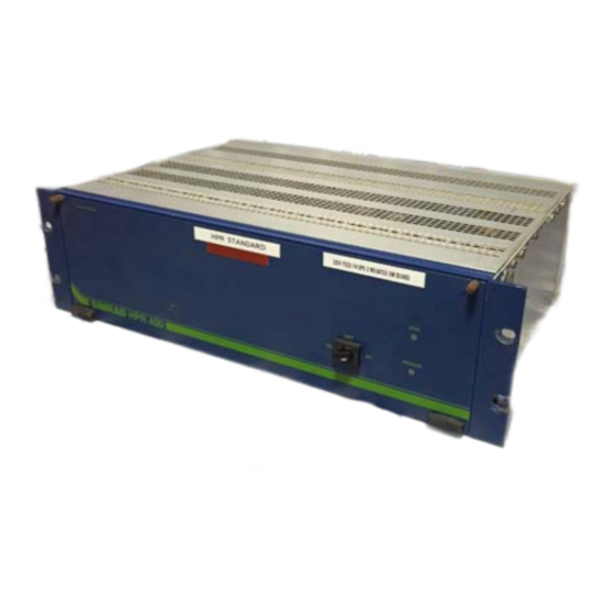
Installation Manual INTRODUCTION This document describes the installation of the HPR 400 Transceiver Unit. The Transceiver Unit contains the transmission and reception electronics for the system, and will normally be located in the sonar room next to the hull unit. -
Page 6: Technical Specifications
HPR 400 Transceiver Unit TECHNICAL SPECIFICATIONS Transceiver Unit Height 135 mm Width 483 mm Depth 310 mm Weight Approximately 20 kg 6U cabinet Height 371 mm Width 600 mm Depth 480 mm Weight Approximately 43 kg Refer to drawing no. 830-102971 in the drawing file for further details of the 6U cabinet dimensions. - Page 7 80% relative Degree of protection (in cabinet) IP 22 If the HPR 400 Transceiver Unit is mounted in a 19” rack, the appropriate protection must be prepared by the installation personnel. The unit must be kept in an operational environment with the room temperature and humidity within the specified limits, and in a dust-free atmosphere.
-
Page 8: Installation
The HPR 400 system computer (APC 10), keyboard and display may be mounted into the same 19” rack. The HPR 400 Transceiver Unit can be supplied installed in a small 19” rack with height 6U. It may also be mounted in an operator console with an integrated keyboard, joystick and display. -
Page 9: Procedures
Installation Manual Procedures 19” rack Introduction The 19” rack is normally a free standing unit, designed to hold a variety of electronic units. The electronic units will normally be positioned in retractable draws or on shelves, or have runners attached directly to them to allow their easy withdrawal from the rack. - Page 10 HPR 400 Transceiver Unit 19” rack installation Note Kongsberg Maritime AS will normally not supply the 19” rack. Any drawings and detailed instructions for installation should therefore be available from the rack supplier. Remove all electronic units before attempting to install the rack.
- Page 11 Installation Manual Position a rectangular threaded strip behind the captive nuts, and screw the brass collar screws into the threaded strip for two or three turns. Position the assembled shelf/slide unit into the rack, locating the lugs on the mounting brackets between the captive nuts and the threaded strips.
-
Page 12: 6U Cabinet
HPR 400 Transceiver Unit 6U cabinet Introduction The 6U cabinet is constructed of formed and welded steel plates, and has a rectangular base. The cabinet has a lockable front door, and divided vertically towards the rear such that it can be hinged open to the left to enable access to the rear of the transceiver unit. - Page 13 Installation Manual Referring to the Cabling and the Cable layout and interconnections sections, fit the required cables through the appropriate cable glands and connect the cable cores into the appropriate terminal blocks within the cabinet. Ensure enough slack is left to enable maintenance to be performed on the unit.
-
Page 14: Cabling
HPR 400 Transceiver Unit CABLING General information All cables to and from the transceiver unit are terminated in plugs on the rear of the unit. If the transceiver unit is mounted in a rack, operator console or other unit mounted on shock absorbers, ensure that 10 cm of slack cable is provided outside the cabinet to allow the unit to move on its shock absorbers without damaging the cable. -
Page 15: Connections
Figure 1 Connectors on the HPR Transceiver Unit’s rear panel The transceiver unit holds the following connectors and fuses used with a HPR 400 P system (top to bottom, left to right when looking at the rear panel): Standard 3-pin, 230 Vac, 50/60 Hz mains power in. - Page 16 HPR 400 Transceiver Unit - This connector is not used with the HPR 400 P. 25-pin D-connector for Parallel input. - This connector is not used with the HPR 400 P. 25-pin D-connector for Analogue input/output. - This connector is used to connect an analogue Vertical Reference Unit.
-
Page 17: Transceiver Unit Pin Allocations
Serial 1 The “Serial 1” socket is a 9-pin delta connector. It is located on the rear panel of the HPR 400 Transceiver Unit, and is identified with the label “SERIAL 1”. It is used for communication with the computer. The inputs and outputs are optically isolated. -
Page 18: Serial 4
Refer to figure 2. Serial 4 The “Serial 4” socket is a 9-pin delta connector. It is located on the rear panel of the HPR 400 Transceiver Unit, and is identified with the label “SERIAL 4”. The serial line is used for synchronization. -
Page 19: Parallel
Installation Manual The “Serial 5” socket is a 9-pin delta connector. It is located on the rear panel of the HPR 400 Transceiver Unit, and is identified with the label “SERIAL 5”. The serial line is used for communication with the APC 10 C computer. -
Page 20: Analogue I/O
HPR 400 Transceiver Unit Analogue I/O The “Analogue” socket is a 25-pin delta connector. It is located on the rear panel of the HPR 400 Transceiver Unit, and is identified with the label “ANALOG IO/”. The pins are allocated as follows:... -
Page 21: Responder 1 - 4
Responder 1 - 4 The Responder 1 to 4 connectors are 4-pin AMP sockets. They are located on the rear panel of the HPR 400 Transceiver Unit, and are identified with the label “TRANSPONDER 1-4”. Figure 5 Responder connector, seen from... -
Page 22: Drawing File
HPR 400 Transceiver Unit DRAWING FILE Overview This section contains drawings referred to in various sections in this manual. The drawings are based on the original system drawings and wiring diagrams. • The original drawings are available in electronic format on request. - Page 23 Installation Manual Note: All measurements are in mm. Cd31167 Page 1 of 1 The drawing is not in scale. 830-088652 Rev.C 130314 / F...
- Page 24 HPR 400 Transceiver Unit Note: All measurements are in mm. Cd31168 Page 1 of 1 The drawing is not in scale. 830-102971 Rev.B 130314 / F...
- Page 25 Installation Manual Note: All measurements are in mm. Cd31169 Page 1 of 1 The drawing is not in scale. 380-088990 Rev.D 130314 / F...
- Page 26 HPR 400 Transceiver Unit 130314 / F...
Need help?
Do you have a question about the HPR 400 and is the answer not in the manual?
Questions and answers