Table of Contents
Advertisement
Quick Links
Advertisement
Table of Contents

Summary of Contents for Nanda NA300 Series
-
Page 2: Table Of Contents
NA300 Series Programmable Logic Controller Technical Specifications and User Manual CONTENT 0 Preface ..........................- 3 - 1 Hardware System Overview ....................7 1.1 Component and Structure of NA300 Hardware System ..........8 1.2 Technical Features of NA300 ..................8 1.3 NA300 System Specifications ..................9 1.4 Product List of NA300 .................... - Page 3 NA300 Series Programmable Logic Controller Technical Specifications and User Manual 6 High Speed Count Module ....................- 88 - 6.1 High-Speed Count Module HCM301-0302 ............- 88 - 6.2 High-Speed Count Module HCM301-0801 ............- 95 - 7 Communication Module ..................... - 105 - 7.1 Serial Communication Module CMM301-0401 ..........- 106 -...
-
Page 4: Preface
NA300 Series Programmable Logic Controller Technical Specifications and User Manual 0 Preface The NA series Programmable Logic Controllers (NA-PLC) are designed and developed independently by Nanda Automation Technology Co., Ltd. NA-PLC draws on the successful experiences of the international main stream PLCs to improve their deficiencies, aims at the latest development of today’s PLC, and adopts a combined... - Page 5 NA300 Series Programmable Logic Controller Technical Specifications and User Manual components do not require significant interruption to the system and there will be no interference to other input and output. CPU boundaries, I/O boundaries, communication network boundaries and Power supply are electrically isolated.These isolation boundaries are examined and approved as providing safe separation.
- Page 6 NA300 Series Programmable Logic Controller Technical Specifications and User Manual control modules, standard functions, but also practical and cost effective functions such as PID, SOE (Sequence of Event) to meet the demand for high-end applications with low costs. Integrating a hardware watch-dog to give a wide range of fault monitoring and diagnosis.
- Page 7 NA300 Series Programmable Logic Controller Technical Specifications and User Manual Various programming languages such as LD, IL, ST, SCC, FBD are supported. English-Chinese bilingual programming makes the code more readable. Friendly GUI with both intelligent graphic and textual edit function.
-
Page 8: Hardware System Overview
NA300 Series Programmable Logic Controller Technical Specifications and User Manual 1 Hardware System Overview □ Synopsis NA300 PLC is a new series of products based on years of Nanda proud extension in PLC research and development experience. Products using low-power embedded processors, fast processing,large memory, communication interface rich,... -
Page 9: Component And Structure Of Na300 Hardware System
1.1 Component and Structure of NA300 Hardware System The hardware system of NA300 series PLC consists of controller modules, sequence of events modules, general I/O modules, communication modules, backplane and system power supply. All modules are installed on the backplane. -
Page 10: Na300 System Specifications
NA300 Series Programmable Logic Controller Technical Specifications and User Manual The program software NAPRO not only supports the four program languages complying with the international standard IEC61131-3, which are Ladder Diagram(LD), Instruction List(IL), Structured Text(ST), and Function Block Diagram(FBD), but also supports the Sequential Control Charts(SCC), which is the most classical language used in sequential control process. - Page 11 NA300 Series Programmable Logic Controller Technical Specifications and User Manual Immunity CISPR 16-2-3 2006 30~230MHz 10m Quasi-peak value < Radiated Interference 40dB(µV/m) Measure 230~1000MHz 10m Quasi-peak value Electromagn etic <47dB(µV/m) Radiation CISPR 16-2-1 2005 Interference 0.15~0.5MHz Quasi-peak value < Conducted Interference 79dB(µV) Average value <66dB(µV)
-
Page 12: Product List Of Na300
NA300 Series Programmable Logic Controller Technical Specifications and User Manual 1.4 Product List of NA300 NA300 PLC hardware product is composed of CPU modules, communication modules, I/O modules, backplane and power supply modules. I/O modules and communication modules can be divided into several types according to the functions. - Page 13 NA300 Series Programmable Logic Controller Technical Specifications and User Manual 300CMM3010109 Profinet Slave 40W,external power supply 24V DC 300PWM3010401 Power Supply Module 300PWM3010403 40W,N+1 Redundant Power supply 24V DC 300BKM3010801 8-slot backplane 300BKM3011201 12-slot backplane Communication Expanding Cable,1m 300CNL3010101 Communication Expanding Cable,2m 300CNL3010201 Communication Expanding Cable,3m...
-
Page 14: Hardware System Configuration Of Na300
NA300 Series Programmable Logic Controller Technical Specifications and User Manual 1.5 Hardware System Configuration of NA300 1.5.1 Power Capacity Check and Configuration For safety considerations, it is suggested that the total power consumption of all modules is less than 70% of the consumption of the selected power supply. -
Page 15: Network Connection
NA300 Series Programmable Logic Controller Technical Specifications and User Manual AOM301-0401 5VDC 520mA 2.6W CMM301-0401 5VDC 350mA 1.75W CMM301-0103 5VDC 400mA CMM301-0204 5VDC 450mA 2.25W CMM301-0118 5VDC 790mA 3.95W CMM301-0109 5VDC 400mA 1.5.2 Network connection Ethernet NA300 CPU has a built-in dual link Ethernet interface, which complies with IEEE802.3/u standard and which is 10/100Mbps self-adapted. -
Page 16: Na300 Software Support
NA300 Series Programmable Logic Controller Technical Specifications and User Manual intelligent devices. It not only saves cables and modules, but also avails inspection and maintenance. CAN Communication Interface CAN communication interface connects NA300 series PLC with external CAN intelligent devices. It not only saves cables and modules, but also avails inspection and maintenance. - Page 17 NA300 Series Programmable Logic Controller Technical Specifications and User Manual Features of NAPro programming software are as following: Comply with IEC-61131 international standard NAPro complies with IEC-61131 international standard, which provides an uniform and effective system configuration environment which makes it possible for the engineers to “learn once, and use everywhere”.
- Page 18 NA300 Series Programmable Logic Controller Technical Specifications and User Manual NAPro supports all five programming languages specified in IEC61131-3. Different languages could be used within a project and could be called by each other. These five languages include: LD:Ladder Diagram ST:Structured text...
- Page 19 NA300 Series Programmable Logic Controller Technical Specifications and User Manual Friendly software design interface NAPro makes the best use of the advantages of Windows graphic and context interface. It improves greatly user friendly experience by optimizing the use of display area, direct visit to tools and information, and bilingual comments, etc..
-
Page 20: Cpu Modules
2 CPU Modules □ Synopsis The CPU module is the core part of NA300 series PLC; it constructs a complete hardware system of PLC by connecting the expansion bus and expansion modules. The CPU module is responsible for self-diagnosis, data acquisition, control of implementation, external communications, and external output functions, etc. -
Page 21: Basic Cpu 301-0101
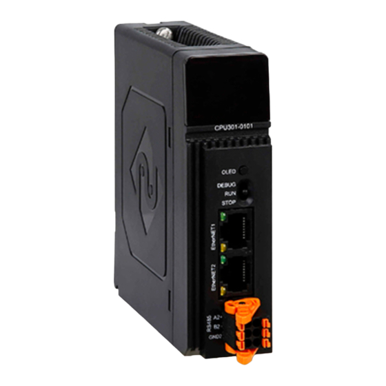
NA300 Series Programmable Logic Controller Technical Specifications and User Manual 2048 32768 CPU has its own maximum allowed number of registers. When writing the programs, please check this information carefully, otherwise the compiler will report errors because of use of registers is beyond limit. - Page 22 NA300 Series Programmable Logic Controller Technical Specifications and User Manual NA300 CPU301-0101 Module LED Indicator description: The LED indicators of CPU modules are located in the upper front panel. As shown below, the status information of CPU is shown by 4 indicator LEDs and OLED.
- Page 23 NA300 Series Programmable Logic Controller Technical Specifications and User Manual Indicator LEDs Color State Meaning Constant lighting / Blue Supply power for the module/No power Constant HIN work normally/ no communication or work Green lighting / off abnormally Fault ( Contain no network cable 、 the fault of Light / off internal bus)/ Running normal...
- Page 24 NA300 Series Programmable Logic Controller Technical Specifications and User Manual IP:192.168.1.111 :Represent the current IP address of Ethernet 1. IP:192.168.1.111 :Represent the current IP address of Ethernet 2. When the state of CPU is debug, OLED screen has 1page. As shown is below.
- Page 25 NA300 Series Programmable Logic Controller Technical Specifications and User Manual CPU external interface diagram OLED screen flip The CPU module OLED screen can display multiple pages,long press the OLED button 2s to switch to the next page to view the next page information.
- Page 26 NA300 Series Programmable Logic Controller Technical Specifications and User Manual The Definition of Serial port is as follows: 4. Ethernet interface CPU module of NA300 CPU301-0101 has two Ethernet interfaces which are used for debugging the downloaded user programs. The Ethernet interface is defined as follows:...
- Page 27 NA300 Series Programmable Logic Controller Technical Specifications and User Manual Support Redundant CPU Ethernet Interface Number RS485 Serial Ports Support baud rate 2.4-38.4kbps Communicate Ability Modbus Program Language Weight(g) Installing Size(Length×Height×Depth)(mm) 32×110×97...
-
Page 28: Power Supply Module
NA300 Series Programmable Logic Controller Technical Specifications and User Manual 3 Power supply module □ Synopsis In order to adapt to different of application situations, NA300 PLC offer several kinds of power supply modules. Power supply modules include LED window, switch, connection terminal etc. - Page 29 NA300 Series Programmable Logic Controller Technical Specifications and User Manual Specification of the switch Position of the switch Definition Power supply module output rated voltage Power supply module output 0V Module outlook NA300-24V Power supply module Specification of LED indicator...
-
Page 30: N+1 Redundant Power Supply Module: Pwm301-0403
NA300 Series Programmable Logic Controller Technical Specifications and User Manual Technical Specification: Module Type PWM301-0401 Order NO. 300PWM3010401 Voltage Input 24VDC Voltage Output +5V Rated Current Connection Mode Terminal Status Indicator Support Weight(g) Installing Size 32×110×97 (Length×Height×Depth)(mm) 3.2 N+1 Redundant Power supply module:... - Page 31 NA300 Series Programmable Logic Controller Technical Specifications and User Manual Principle of The Redundancy The N+1 power rail controller, in conjunction with an external N-channel MOSFET, emulates the function of a low forward voltage diode. PWM301-0403 Power Supply Example The N+1 power supply configuration shown above is used where multiple power supplies are paralleled for either higher capacity, redundancy or both.
- Page 32 NA300 Series Programmable Logic Controller Technical Specifications and User Manual Specification of the switch Position of the key switch Definition Power supply module output rated voltage Power supply module output 0V Module outlook Power supply module PWM301-0403 Definition of LED...
- Page 33 NA300 Series Programmable Logic Controller Technical Specifications and User Manual Blue Light / off Bus Power on/Bus Power off Flicker/Constant Run normally/ Run but parameters are not Green Lighting loaded Constant Green HIN work normally/ abnormally Lighting / off Light / off...
-
Page 34: Digital I/O Module
Digital output module DOM301-1601 Digital output module DOM301-3201 NA300 series PLC provide many kinds of digital expand modules for users, including normal digital input module NA300 DIM301, sequence of events input module, NA300 IIM301 and digital output module. Please see table 4.1 for more information. -
Page 35: Digital Input Module Dim301-1601:Di16×Dc24V
NA300 Series Programmable Logic Controller Technical Specifications and User Manual DIM301-3201 32 channel Digital input module DI32×DC24V (Sink or Source) IIM301-1601 16 channel SOE module IIM16×DC24V IIM301-3201 32 channel SOE module IIM32×DC24V DOM301-1601 16 channel Digital output module DO16×DC24V×Transistor DOM301-3201 32 channel Digital output module DO32×DC24V×Transistor... - Page 36 NA300 Series Programmable Logic Controller Technical Specifications and User Manual Diagram of DIM301-1601 Single Channel Interface Circuit Terminal wiring diagram DIM301-1601 Digital input module connect with external devices by terminal blocks in front of the module. Correspondence of each channel is described in the following figure.
- Page 37 NA300 Series Programmable Logic Controller Technical Specifications and User Manual DIM301-1601Terminal wiring diagram Indicator LED description:...
- Page 38 NA300 Series Programmable Logic Controller Technical Specifications and User Manual Indicator LEDS Description of indicator LEDs: Color State Meaning Constant Lighting/ Blue Power on/off Flicker/Constant Run normally/run but parameters are not Green Lighting loaded Constant Lighting / Green HIN work normally/ abnormally...
- Page 39 NA300 Series Programmable Logic Controller Technical Specifications and User Manual input signal is 1,otherwise it is 0. Technical Specification Points Input Type Sink or source Module Load 200mA/5V Power Consumption Self Diagnosis Function 10~100ms manually Input Filter Insulation Test 500VDC...
-
Page 40: Digital Input Module Dim301-3201:Di32×Dc24V
NA300 Series Programmable Logic Controller Technical Specifications and User Manual 4.2 Digital input module DIM301-3201:DI32×DC24V Order Number 300DIM3013201 Features: 1. 32 points input with 16 points (also called “channels”) per group sharing a common terminal, source or sink input type. - Page 41 NA300 Series Programmable Logic Controller Technical Specifications and User Manual common terminals. 32 channels can be divided into 2 groups, each of which requires a separate 24VDC filed power supply. NO. “17,35” pin is the input common terminal of field power supply, as the common ...
- Page 42 NA300 Series Programmable Logic Controller Technical Specifications and User Manual DIM301-3201 Terminal wiring diagram Indicator LED description:...
- Page 43 NA300 Series Programmable Logic Controller Technical Specifications and User Manual Indicator LEDS Descriptions of indicator LEDs: Color State Meaning Constant Lighting/ Blue Power on/off Flicker/Constant Run normally/run but parameters are not Green Lighting loaded Constant Lighting / Green HIN work normally/ abnormally...
-
Page 44: Sequence Of Event (Soe) Module Iim301-1601:Iim16×Dc24V
NA300 Series Programmable Logic Controller Technical Specifications and User Manual Technical Specification Points Input Type Sink or source Module Load 320mA/5V Power Consumption 1.6W Self Diagnosis Function 10~100ms manually Input Filter Insulation Test 500VDC Nominal Input Voltage 24VDC 14~30V “1”Signal Voltage -30~5V... - Page 45 NA300 Series Programmable Logic Controller Technical Specifications and User Manual 4. Every DI point could be set 10~100ms filtering time by software. 5. Intelligent module with self-diagnosis function can be reset and reboot automatically when fault. 6. No need for hardware setting. The CPU Module can load parameters on it automatically after start up.
- Page 46 NA300 Series Programmable Logic Controller Technical Specifications and User Manual Every 8 channels form a group and share a common terminal. There are all two common terminals. 16 channels can be divided into 2 groups, each of which requires a separate 24VDC filed power supply.
- Page 47 NA300 Series Programmable Logic Controller Technical Specifications and User Manual IIM301-1601Terminal wiring diagram Indicator LED description:...
- Page 48 NA300 Series Programmable Logic Controller Technical Specifications and User Manual Indicator LEDS Description of indicator LEDs: Color State Meaning Constant Lighting/ Blue Power on/off Flicker/Constant Run normally/run but parameters are not Green Lighting loaded Constant Lighting / Green HIN work normally/ abnormally...
-
Page 49: Sequence Of Event (Soe) Module Iim301-3201:Iim32×Dc24V
NA300 Series Programmable Logic Controller Technical Specifications and User Manual input signal is 1,otherwise it is 0. Technical Specification Points Input Type Sink or source Module Load 200mA/5V Power Consumption Self Diagnosis Function 10~100ms manually Input Filter Insulation Test 500VDC... - Page 50 NA300 Series Programmable Logic Controller Technical Specifications and User Manual 3. Applicable to switch and 2/3/4 proximity switch. 4. Every DI point could be set 10~100ms filtering time by software. 5. Intelligent module with self-diagnosis function can be reset and reboot automatically when fault.
- Page 51 NA300 Series Programmable Logic Controller Technical Specifications and User Manual common terminals. 32 channels can be divided into 2 groups, each of which requires a separate 24VDC filed power supply. NO. “17,35” pin is the input common terminal of field power supply, as the common ...
- Page 52 NA300 Series Programmable Logic Controller Technical Specifications and User Manual IIM301-3201Terminal wiring diagram Indicator LED description:...
- Page 53 NA300 Series Programmable Logic Controller Technical Specifications and User Manual Indicator LEDS Description of indicator LEDs: Color State Meaning Constant Lighting/ Blue Power on/off Flicker/Constant Run normally/run but parameters are not Green Lighting loaded Constant Lighting / Green HIN work normally/ abnormally...
-
Page 54: Digital Output Module Dom301-1601:Do16×Dc24V×Transistor
NA300 Series Programmable Logic Controller Technical Specifications and User Manual Technical Specification Points Input Type Sink or source Module Load 320mA/5V Power Consumption 1.6W Self Diagnosis Function 10~100ms manually Input Filter Insulation Test 500VDC Nominal Input Voltage 24VDC 14~30V “1”Signal Voltage -30~5V... - Page 55 NA300 Series Programmable Logic Controller Technical Specifications and User Manual 4. Intelligent module with self-diagnosis function can be reset and reboot automatically when fault. 5. No need for hardware setting. The CPU Module can load parameters on it automatically after start up.
- Page 56 NA300 Series Programmable Logic Controller Technical Specifications and User Manual DOM301-1601Terminal wiring diagram Indicator LED description:...
- Page 57 NA300 Series Programmable Logic Controller Technical Specifications and User Manual Indicator LEDS Description of indicator LEDs: Color State Meaning Blue Lighting/ off Power on/off Flicker/Constant Run normally/run but parameters are not Green Lighting loaded Green Lighting / off HIN work normally/ abnormally...
- Page 58 NA300 Series Programmable Logic Controller Technical Specifications and User Manual Technical Specification Points Module Load 300mA/5V Power Consumption 1.5W Output Voltage 24VDC Transistor,source type Output Type Continuous current per channel(0~ 0.5A 40℃) Maximum continuous current per channel 0.6A,100ms (0~40℃) Minimum continuous current per channel...
-
Page 59: Digital Output Module Dom301-3201:Do32×Dc24V×Transistor
NA300 Series Programmable Logic Controller Technical Specifications and User Manual 4.6 Digital output module DOM301-3201:DO32×DC2 4V×Transistor Order Number 300DOM3013201 Features: 1. 32 points output with isolation, 16 points(also called “channels”) per group using a common terminal. 2. Rated output type 24VDC transistor, source type of output. - Page 60 NA300 Series Programmable Logic Controller Technical Specifications and User Manual DOM301-3201Digital output module connects with external devices by terminal blocks in front of module. Correspondence of each channel is described in the following drawing. And please pay attention to the following:...
- Page 61 NA300 Series Programmable Logic Controller Technical Specifications and User Manual DOM301-3201 Terminal wiring diagram Indicator LED description:...
- Page 62 NA300 Series Programmable Logic Controller Technical Specifications and User Manual Indicator LEDS Descriptions of indicator LEDs: Color State Meaning Blue Lighting/ off Power on/off Flicker/Constant Run normally/run but parameters are not Green Lighting loaded Green Lighting / off HIN work normally/ abnormally...
- Page 63 NA300 Series Programmable Logic Controller Technical Specifications and User Manual Points Module Load 450mA/5V Power Consumption 2.25W Output Voltage 24VDC Transistor,source type Output Type Continuous current per channel 0.5A Maximum load current(0~40℃) 0.6A,100ms Minimum load current(0~40℃) Resistive Loading 100Hz Switching...
-
Page 64: Analog I/O Module
Current/voltage mode AI module AIM301-0801 RTD mode AI module AIM301-0805 Thermocouple mode AI module AIM301-0806 Current/voltage mode AO module AOM301-0401 NA300 series PLC provides many kinds of analog expand modules for users. more information, please see List 5.1. List 5.1 Analog Module Type... - Page 65 NA300 Series Programmable Logic Controller Technical Specifications and User Manual Features: 1. 8 channel current mode AI module. 2. Measurement accuracy is 16 bit. 3. Signal form:Single-ended input. 4. Intelligent module with self-diagnosis function can be reset and reboot automatically when fault.
- Page 66 NA300 Series Programmable Logic Controller Technical Specifications and User Manual Do not supply power to transmitter with input channel. A separate 24V DC power supply must be used when a two-wired transmitter is connected. Prohibition of wiring: “1”、“2” 、“19”、“20”.
- Page 67 NA300 Series Programmable Logic Controller Technical Specifications and User Manual display the analog module information. The four LEDs are power indicator P, run indicator R, communication status indicator A and fault indicator F. OLED screen is used to display the voltage or current value collected by the channel.
-
Page 68: Analog Input Module Aim301-0805:Ai8×Rtd
NA300 Series Programmable Logic Controller Technical Specifications and User Manual The number of channels Power Consumption 1.9W/5V -10~10V (0~20000) 0~5V (0~20000) -5~5V (0~20000) 1~5V (4000~20000) Signal Type 0~10V (0~20000) 4~20mA (4000~20000) 0~20mA (0~20000) 0~10mA (0~20000) 0~20000 Data Type Maximum Current... - Page 69 NA300 Series Programmable Logic Controller Technical Specifications and User Manual 2. The type of thermistor for each channel can be set optionally. 3. Measurement of each channel:RTD. 4. Wiring mode:Two-wire、Three-wire. 5. Measurement accuracy is 24 bit. 6. Intelligent module with self-diagnosis function can be reset and reboot automatically when fault.
- Page 70 NA300 Series Programmable Logic Controller Technical Specifications and User Manual "3,5,7,9", "4,6,8,10" are the input terminals for the first and the second channel of temperature signals, and please see the terminal wiring diagram for other signal wiring method. If the resistance which is provided by user is of two-wire, B, C terminals of input ...
- Page 71 NA300 Series Programmable Logic Controller Technical Specifications and User Manual Display area description: The status indication for the AIM301-0805 module is located directly above the module's front panel.As shown below,display the RTD module information with 4 LED indicators and an OLED screen. The four LEDs are the power indicator P, the operation indicator R, the communication status indicator A and the fault indicator F, the OLED screen is used for displaying the measured temperature value of the channel.
-
Page 72: Analog Input Module Aim301-0806:Ai8×Thermocouple
NA300 Series Programmable Logic Controller Technical Specifications and User Manual A: Communication indicator LED. When CPU module can communicate normally with other modules through HIN, the LED is on. F: Fault indicator LED. The LED is on when the modules has fault. The LED ... - Page 73 NA300 Series Programmable Logic Controller Technical Specifications and User Manual 8 channel thermocouple(TC)differential input. The type of thermocouple can be set optionally. Measurement of each channel:Thermocouple. Measurement accuracy is 24 bit. Intelligent module with self-diagnosis function can be reset and reboot automatically ...
- Page 74 NA300 Series Programmable Logic Controller Technical Specifications and User Manual AIM301-0806 Terminal wiring diagram A、B、C、D is the input of RTD for m easuring of the temperature of cold Terminal。 Terminal wiring diagram...
- Page 75 NA300 Series Programmable Logic Controller Technical Specifications and User Manual AIM301-0806 RTD cold Terminal wiring diagram Indicator LED description: Module display area diagram Color State Meaning Blue Constant Lighting/ off Power on/ Power off Flicker/ Constant Run normally/ program has been...
- Page 76 NA300 Series Programmable Logic Controller Technical Specifications and User Manual information. Technical Specification The number of channels Unit of measurement ℃ Power Consumption 2W/5V Signal Type S、T、R、E、N、J、K Actual value×10(32767 when signal Data Type offline) Maximum Input Voltage 20VDC 24bits Resolution Elementary Error 0.05%FS(Voltage)
-
Page 77: Analog Input Module Aim301-1602: Ai16×Current Type
NA300 Series Programmable Logic Controller Technical Specifications and User Manual -0~1700 0~17000 -0~1700 0~17000 -200~1200 -2000~12000 -200~400 -2000~4000 -200~1300 -2000~13000 -20~520 -200~5200 * The final value of module collection is the data of increasing cold forging compensation temperature treatment. 5.4 Analog Input module AIM301-1602: AI16×current type... - Page 78 NA300 Series Programmable Logic Controller Technical Specifications and User Manual The current signal is converted into a digital signal by current-voltage conversion, filtering, and A/D. After photoelectric isolation, the module's micro The processor reads and then uploads to the controller master via the high-speed internal bus.
- Page 79 NA300 Series Programmable Logic Controller Technical Specifications and User Manual AIM301-1602 terminal wiring diagram Display area description: The status indication of the AIM301-1602 module is located just above the front panel of the module. As shown in the figure below, 4 LED indicators and an OLED screen are used to display the information of the analog module.
- Page 80 NA300 Series Programmable Logic Controller Technical Specifications and User Manual Schematic diagram of the module display area Indicator LEDs Color State Meaning Blue Constant Lighting/ off Power on/ Power off Flicker/ Constant Run normally/ program has been running Green Lighting...
- Page 81 NA300 Series Programmable Logic Controller Technical Specifications and User Manual number of channels Power consumption 1.9W/5V 0~20mA 4~20mA signal type 0~10mA Data Format 0~20000 4000~20000 Maximum input current 20mA Operating Limits Over the Entire 0.2% Temperature Range Acquisition accuracy 0.2%...
- Page 82 NA300 Series Programmable Logic Controller Technical Specifications and User Manual Features: 1. 4 channel current/voltage output. 2. Output range of each channel:Voltage output:0~5V、1~5V、-5V~5V、0V~10V 、 -10V~10V; Current output:4~20mA、0~20mA、0~10mA 3. Measurement accuracy is 16 bit. 4. Intelligent module with self-diagnosis function can be reset and reboot automatically when fault.
- Page 83 NA300 Series Programmable Logic Controller Technical Specifications and User Manual Diagram of AOM301-0401 Single Channel Interface Circuit Terminal wiring diagram AOM301-0401 AO module connects with external devices by terminal blocks in front of module. Correspondence of each channel is described in the following drawing.
- Page 84 NA300 Series Programmable Logic Controller Technical Specifications and User Manual AOM301-0401 Terminal wiring diagram Display area description: The status indication for the AIM301-0401 module is located directly above the module's front panel.As shown below, display the RTD module information with 4 LED indicators and an OLED screen.
- Page 85 NA300 Series Programmable Logic Controller Technical Specifications and User Manual OLED screen is mainly used to display the 4-channel output analog value and fault information. Indicator LED description: Display area diagram Indicator LEDs Color State Meaning Blue Constant Lighting/ off...
- Page 86 NA300 Series Programmable Logic Controller Technical Specifications and User Manual F: Fault indicator LED. The LED is on when the module external 24VDC is abnormal. The LED will go off when everything is normal. OLED screen display: Corresponding to the voltage and current values of ...
- Page 87 NA300 Series Programmable Logic Controller Technical Specifications and User Manual Technical Specification The number of channels Power Consumption 2.6W/5V Current,Voltage Output Type -10~10V (0~20000) 0~5V (0~20000) -5~5V (0~20000) 1~5V (4000~20000) Output Range 0~10V (0~20000) 4~20mA (4000~20000) 0~20mA (0~20000) 0~10mA (0~20000)...
- Page 88 NA300 Series Programmable Logic Controller Technical Specifications and User Manual Weight 140g - 87 -...
-
Page 89: High Speed Count Module
NA300 Series Programmable Logic Controller Technical Specifications and User Manual 6 High Speed Count Module □ Synopsis HCM301 , an intelligent count module, is widely used in count and measurement . It has direct-connect Gate signal capture 24-V incremental encoder 、 Orientation sensor、Starter and... - Page 90 NA300 Series Programmable Logic Controller Technical Specifications and User Manual Supports 1 reflection output based on the comparison result of each channel; The hardware cycle obtains the position value of the SSI encoder, and the fixed cycle is 1ms;...
- Page 91 NA300 Series Programmable Logic Controller Technical Specifications and User Manual Indicator LEDs Led Color Status Meaning flashing / R green Module normal operation / module failure constant light The module is sending data normally in the internal A green ON/OFF...
- Page 92 NA300 Series Programmable Logic Controller Technical Specifications and User Manual C11green ON/OFF Channel 2 captures 1 signal level state, high/low level Channel 2 reflected output signal level status, high/low Q1 green ON/OFF level The 3rd channel SSI encoder has normal input/no normal...
- Page 93 NA300 Series Programmable Logic Controller Technical Specifications and User Manual provided by the encoder. The upper limit is 31. The status bit is a status flag that is refreshed when this bit is received in the sequence. For some encoders, this bit can indicate errors detected in the data frame.
- Page 94 NA300 Series Programmable Logic Controller Technical Specifications and User Manual Pin Name Function Remark D0 +, D 1+, D2+ SSI encoder DATA+ signal D0-, D1-, D2- SSI encoder DATA-signal C0+, C1+, C2+, SSI encoder CLK+ signal C0-, C1-, C2-, SSI encoder CLK-signal...
- Page 95 NA300 Series Programmable Logic Controller Technical Specifications and User Manual OFF: <5Vdc CP01, CP11, CP21 2nd capture input Q0, Q1, Q2 Reflected output source output 24V0+, 24V1+, Encoder 24V+ power input 24V2+, Encoder 24V-power ground 24V0-, 24V1-, 24V2- input This module is externally...
-
Page 96: High-Speed Count Module Hcm301-0801
NA300 Series Programmable Logic Controller Technical Specifications and User Manual interface (tolerance: 19.2-30 Vdc) Encoder Power Voltage: 24 VDC (powered by this module) Weight 250g Dimensions (W×H×D) (mm) 40×145×162 High-Speed Count Module HCM301-0801 Order Number: 300HCM301-0801 Features: Support 8 single-phase high-speed counting inputs;... - Page 97 NA300 Series Programmable Logic Controller Technical Specifications and User Manual NA300HCM301-0801 High-speed counting modul Module light definition The following table describes the LED display area indicators of the NA300HCM301-0801 module and their working status: LED display area indicator Light Light Status...
- Page 98 NA300 Series Programmable Logic Controller Technical Specifications and User Manual Color flashing/constant green Module normal operation / module failure light The module is sending data normally in the green ON/OFF internal network /sending data abnormally The light is on to indicate that the module is...
- Page 99 NA300 Series Programmable Logic Controller Technical Specifications and User Manual Channel 2 function input signal I_AUX2 input green ON/OFF level, high/low level Channel 3 function input signal I_AUX3 input green ON/OFF level, high/low level Channel 4 function input signal I_AUX4 input...
- Page 100 NA300 Series Programmable Logic Controller Technical Specifications and User Manual weight 140g Dimensions ( W × H × D ) ( mm) 32 × 110 × 97 Terminal wiring diagram The HCM301-0801 high-speed counting module is wired with external devices through...
- Page 101 NA300 Series Programmable Logic Controller Technical Specifications and User Manual NA300HCM301-0801Terminal wiring diagram - 100 -...
- Page 102 NA300 Series Programmable Logic Controller Technical Specifications and User Manual Single Channel Wiring Schematic NA300HCM301-0801 Single Channel Wiring Schematic Note: Taking the nth channel (the value range of n is 1 to 8) as an example, when the input signal is 24V, the positive terminal of the input signal is input to the terminal. Sub Sn_A, the negative terminal is connected to the terminal Sn-;...
- Page 103 NA300 Series Programmable Logic Controller Technical Specifications and User Manual V) , positive terminal phase counting , positive terminal channel 2 Pulse input signal S2- , channel 1 B1 -input of bi-phase S2-/B1- negative terminal counting , negative terminal channel 3 Pulse input signal S3_A...
- Page 104 NA300 Series Programmable Logic Controller Technical Specifications and User Manual S6_B/B5+ Channel 6 Pulse input signal S6_B Channel 5 B5+ input (5V) of two- (5 V) , positive terminal phase counting , positive terminal S6-/B5- Channel 6 Pulse input signal S6- ,...
- Page 105 NA300 Series Programmable Logic Controller Technical Specifications and User Manual GCOM I_AUX , externally grounded - 104 -...
-
Page 106: Communication Module
NA300 Series Programmable Logic Controller Technical Specifications and User Manual 7 Communication Module □ Synopsis NA300 controllers support communication protocols to communicate with third party local intelligent devices, such as MODBUS,PROFIBUS-DP, Ethernet and so on. If NA300 control system is to provide a certain communication function, this can be achieved by simply installing an appropriate communication module on the backplane. -
Page 107: Serial Communication Module Cmm301-0401
NA300 Series Programmable Logic Controller Technical Specifications and User Manual CMM301-0204 Double CAN Module Two way of CAN interface Ethernet Substation Module CMM301-0118 Ethernet Substation CMM301-0118 CMM301-0109 Profinet Slave Module CMM301-0401 Profinet Slave Module 7.1 Serial Communication Module CMM301-0401 Order Number... - Page 108 NA300 Series Programmable Logic Controller Technical Specifications and User Manual Outlook CMM301-0401 Indicator LED description: Indicator LEDs - 107 -...
- Page 109 NA300 Series Programmable Logic Controller Technical Specifications and User Manual Color State Function Blue Light/ off Power on / off Flicker/ Constant Run normally/ program is running but Green Lighting parameters are not loaded Green Light/ off HIN work normally/ abnormally...
- Page 110 NA300 Series Programmable Logic Controller Technical Specifications and User Manual ER1~ER4:Data transmission or receiving abnormal indicating lights for four serial ports (COM1 ~COM4). The corresponding “ER” lamp is on when the serial port is sending or receiving data abnormal.
- Page 111 NA300 Series Programmable Logic Controller Technical Specifications and User Manual Communication modules connect with external devices by terminal blocks in front of module. The module provides standard RS-485 serial communication interface. Each communication port has an indicator LED. CMM301-0401 Terminal wiring diagram...
-
Page 112: Profibus Dp Slave Communication Module Cmm301-0103
NA300 Series Programmable Logic Controller Technical Specifications and User Manual 7.2 Profibus DP Slave Communication Module CMM301-0103 Order Number 300CMM3010103 Features: 1. Standard ROFIBUS-DP slaver interface, DP-V0/V1,complying with IEC61158 and GB/T 20540-2006: the third part of “Digital data communication for measurement and control - Fieldbus for use in industrial systems”. - Page 113 NA300 Series Programmable Logic Controller Technical Specifications and User Manual Outlook CMM301-0103 Indicator LED description: The table below describes LED display indication and work status of DP slave communication module CMM301-0103. Indicator LEDs - 112 -...
- Page 114 NA300 Series Programmable Logic Controller Technical Specifications and User Manual Color State Function Blue Light/ off Power Supply normal / abnormal Flicker/ Run normally/ program is running but Green Constant parameters are not loaded Lighting Green Light/ off HIN work normally/ abnormally...
- Page 115 NA300 Series Programmable Logic Controller Technical Specifications and User Manual RDY: Main control exchanging data with Profibus indicator LED. When it blinks, data exchange goes normally. When it lights always or goes off, data exchange goes abnormally. STA: Slave Configuration Indicator LED. It goes on when receiving data ...
- Page 116 NA300 Series Programmable Logic Controller Technical Specifications and User Manual The DP slave address is equal to S1*1+S2*10, which should be set correctly before power up. 2. DP Communication port DP-S:standard SUB DB9 Female port,the pin definition is shown as follows:...
-
Page 117: Double Can Module Cmm301-0204
NA300 Series Programmable Logic Controller Technical Specifications and User Manual 7.3 Double CAN Module CMM301-0204 Order Number 300CMM3010204 Features: 1. Dual CAN interface, custom protocol communication. 2. Baud rate free programming configuration, supporting 5K-1000K basic baud rate. 3. The maximum input of internal communication is120 words(240Bytes), output is 120words(240Bytes). - Page 118 NA300 Series Programmable Logic Controller Technical Specifications and User Manual CMM301-0204 Indicator LED description: The table below describes LED display indication and work status of Double CAN module CMM301-0204: Indicator LEDs Color State Function - 117 -...
- Page 119 NA300 Series Programmable Logic Controller Technical Specifications and User Manual Blue Light/ off Power Supply normal / abnormal Flicker/Const Run normally/ program is running but Green ant Lighting parameters are not loaded Green Light/ off HIN work normally/ abnormally Light/ off...
- Page 120 NA300 Series Programmable Logic Controller Technical Specifications and User Manual turns off. F: Fault Indicator LED. The LED is light when the module is fault. TX1: Indicator of CAN1 sending data,sending data is light/No data is sending, light is off.
- Page 121 NA300 Series Programmable Logic Controller Technical Specifications and User Manual Hardware Setting and Communication Interface of CMM301-0204 1. CAN module address switch The module each CAN provides two decimal rotary address encoder switches as shown below. The above two dial switch can set CAN1 address, the address of CAN1 is equal to S1+S2*10, which should be set correctly before power up.
-
Page 122: Ethernet Substation Cmm301-0118
NA300 Series Programmable Logic Controller Technical Specifications and User Manual CAN1+、CAN1- and CAN2+、CAN2-:interface terminal of 2 way of CAN, access to the on-site CAN bus by shielded twisted pair. Res1+、 Res1- and Res2+、 Res2-: There are two CAN interface terminating resistor enable terminals, for examples: Res1+, Res1- terminal vacancy. - Page 123 NA300 Series Programmable Logic Controller Technical Specifications and User Manual uplink and downlink. 6. Supports up to 2 backplanes (12 slots). 7. Support serial port module. 8. Two ring network ports have By-pass function. Outlook CMM301-0118 Mounting dimensions (width×height×depth):32mm×110mm×97mm. LED indicator:...
- Page 124 NA300 Series Programmable Logic Controller Technical Specifications and User Manual 0.5 seconds, off for 0.5 seconds). The specific definitions are shown below. CMM301-0118 Substation Indicator Meaning Color State Meaning Constant Lighting/ Blue Power on/ Power off Flicker/Constant Run normally/ Program has been running...
- Page 125 NA300 Series Programmable Logic Controller Technical Specifications and User Manual The working state corresponding to the indicator LED is as follows: P: Power indicator LED. When module power on ,the LED is on; When module power off ,the LED is off.
- Page 126 NA300 Series Programmable Logic Controller Technical Specifications and User Manual works normally, the indicator is on when the substation dial code is changed but the module is not restarted, and the indicator flicker when there is the IP conflict between the substation module and the network.
- Page 127 NA300 Series Programmable Logic Controller Technical Specifications and User Manual Technical Specification Communication module type CMM301-0118 Order number 300CMM3010118 Power consumption <6W Current consumption <1.2A@5V Physical interface 3 RJ45 ports (only 1 IP address) Communication Port Protocol Custom protocol, named NARING...
- Page 128 NA300 Series Programmable Logic Controller Technical Specifications and User Manual CPU download network port to other service ports that are connected to the ring network module). (2)Port mirroring (S1 is placed in F position, and S2 is arbitrary): In this mode, the data traffic of the other 2 ports is copied to this port, so that the connected tools can be used to monitor and analyze the port traffic.
-
Page 129: Profinet Slave Communication Module Cmm301-0109
NA300 Series Programmable Logic Controller Technical Specifications and User Manual Set the substation number by dialing The substation module provides two hexadecimal rotary code switches S1 and S2, but the substation number only uses the lower 10 bits of S1 and S2 (S1 range is 0-9, S2 range is 0-9). - Page 130 NA300 Series Programmable Logic Controller Technical Specifications and User Manual 2. Connect the NA300 IO module through the backplane bus. 3. Connect the NA300 other communication modules through the backplane bus. 4. There are 2 RJ45 interfaces externally. 5. Support the following Ethernet services: ping, arp, network diagnostics.
- Page 131 NA300 Series Programmable Logic Controller Technical Specifications and User Manual Indicator LEDs The LED indicator is only on, off, or flicker (flashing means the indicator is on for 0.5 seconds, off for 0.5 seconds). 1.Indicator LED of P/R/A/F Color State...
- Page 132 NA300 Series Programmable Logic Controller Technical Specifications and User Manual Interface module is configured Module reset to factory settings Light Irrelevant Irrelevant The module is in data exchange with the IO device. Irrelevant Flicker Irrelevant The configured architecture does not...
- Page 133 NA300 Series Programmable Logic Controller Technical Specifications and User Manual PROFINET interface also flash) 4. Indicator LED of external network port Color State Function Light 100M link detected LINK Green 10M link detected Light Link is connected but no data...
- Page 134 NA300 Series Programmable Logic Controller Technical Specifications and User Manual Technical Specification CMM type CMM301-0109 Order NO. 300CMM3010109 Power Consumption <5.0W Current Consumption <1A@5V Number of communication port Type of the Port RJ45 Transmission mode PROFINET,100 Mbit/s,Full duplex(100BASE-TX) Physical 10 Mbit/s...
- Page 135 NA300 Series Programmable Logic Controller Technical Specifications and User Manual Transmission support media PROFINET connector and PROFINET cable Communication Program Programmable mode Operating temperature -15℃-55℃ Power supply Rack power Weight <1kg Dimensions W×H×D(mm) 32mm×110mm×97mm - 134 -...
-
Page 136: Canopen Master Module Cmm 301-0104
NA300 Series Programmable Logic Controller Technical Specifications and User Manual 7.6 CANOpen Master Module CMM 301-0104 Order Number: 300CMM 301-0104 Features: Complete communication tasks independently, both with NA300PLC/NJ300PLC Data exchange, also with CANOpen slave data exchange. A separate intranet is used for data exchange with NA300PLC/NJ300PLC module,... - Page 137 NA300 Series Programmable Logic Controller Technical Specifications and User Manual Comprehensive LED indication function The configuration parameters will not be lost when the power is turned off. After the power is turned on, the CPU will automatically load the parameters.
- Page 138 NA300 Series Programmable Logic Controller Technical Specifications and User Manual Color Status Meaning flashing / green Module normal operation / module failure constant light The module is sending data normally in green ON/OFF the internal network /sending data abnormally The light is on to indicate that the module...
- Page 139 NA300 Series Programmable Logic Controller Technical Specifications and User Manual Model 300CMM301-0104 order number 300CMM311-0104 Power consumption 3.0W/5V current consumption 600mA/5V Number of communication ports Interface Type 6-pin open CANOpen connector, CAN interface 50kbps, 100kbps, 125kbps, 250kbps, 500kbps, 800kbps, Support common baud rate...
- Page 140 NA300 Series Programmable Logic Controller Technical Specifications and User Manual address dial The address dialing code is not used yet, the default address of the master station is 0 4. function dial Dial code reserved for use - 139 -...
-
Page 141: Na300 System Configuration
NA300 Series Programmable Logic Controller Technical Specifications and User Manual 8 NA300 System Configuration □ Synopsis NA300 intelligent programmable controller provides flexible system configuration, in which I/O module includes local I/O and remote I/O. Because different types of NA300 PLC modules can be fixed in any position of the backplane, flexibility of system configuration is greatly improved. -
Page 142: How To Choose Cpu
NA300 Series Programmable Logic Controller Technical Specifications and User Manual module 300DOM3013201 DO32×DC24V×Transistor Source 300IIM3011601 IIM16×DC24V Sink and Source SOE module 300IIM3013201 IIM32×DC24V Sink and Source 0~20mA AI4×current/voltage×Singl 300AIM3010401 e-ended input -10V~10V AI8×current/voltage×Singl 0~20mA Analog input 300AIM3010801 module e-ended input... - Page 143 NA300 Series Programmable Logic Controller Technical Specifications and User Manual Maximum I/O points of CPU. Calculation of CPU’s Memory size: Memory size is the size of hardware memory unit in PLC, while program size is the size used in a memory unit to store user program. Therefore, program size is usually smaller than memory size.
-
Page 144: How To Choose Backplane
NA300 Series Programmable Logic Controller Technical Specifications and User Manual 8.3 How to choose backplane 8.3.1 Backplane type NA300 PLC backplane has two different types: eight-slot and twelve-slot. The number of backplane should be chosen according to the number of I/O modules calculated. -
Page 145: Bus Expansion
NA300 Series Programmable Logic Controller Technical Specifications and User Manual Backplane address: There is a rotary switch on each backplane used to set its address as 0~7(8-F unused). Module address: Module address is decided by the module’s backplane address and slot number. - Page 146 NA300 Series Programmable Logic Controller Technical Specifications and User Manual 300NUL3010101 Null module 300BUS3010101 Bus terminal adapter 36-core module connection 300CNE3013601 terminal - with release lever 36-core module connection 300CNE3013602 terminal - screw fixed 18-core module connection 300CNE3011801 terminal - with release lever...
- Page 147 NA300 Series Programmable Logic Controller Technical Specifications and User Manual terminal - screw fixed - 146 -...
-
Page 148: Hardware Mounting
NA300 Series Programmable Logic Controller Technical Specifications and User Manual 9 Hardware Mounting □ Synopsis CPU module, power supply module and I/O module of NA300 PLC are always fixed to the backplanes , and the backplanes are fixed to the cabinets. This chapter introduces the installation size of holes and the right way to fix modules and backplanes. -
Page 149: Mounting Of The Module
NA300 Series Programmable Logic Controller Technical Specifications and User Manual Hole dimension on 12-slot backplane 9.2 Mounting of the module Mounting position of the module NA300 intelligent PLC has no restrictions in the mounting slots for the different types of modules. - Page 150 NA300 Series Programmable Logic Controller Technical Specifications and User Manual Step C: Press the module down so that the module is fully in contact with the connector on the backplane while ensuring that the module's fastening screw can be inserted into the threaded hole in the backplane.
-
Page 151: Accessories
NA300 Series Programmable Logic Controller Technical Specifications and User Manual 10 Accessories Related accessories of NA300 PLC that need to order separately are listed as below: NA300 PLC Accessories Description Order no 8-slot backplane 300BKM3010801 12-slot backplane 300BKM3011201 Bus expansion cable, the length is 300CNL3010101 1.0m... - Page 152 NA300 Series Programmable Logic Controller Technical Specifications and User Manual AOM301-0401 Choose the type according to 16-point IO module 18-core module connection terminal 300CNE3011801 Choose the type according to - with release lever AIM301-0401 Choose the type according to AIM301-0405...
- Page 153 NA300 Series Programmable Logic Controller Technical Specifications and User Manual - 152 -...